Brian's Melnichenko's Effect Replication

  • 1.7K Views
  • Last Post 14 July 2022
Brian posted this 15 June 2022

Hi team

I am waiting on the IGBT for this circuit.

Thought I would post a quick pic to support Jagau and keep the thread alive.

I really appreciate the efforts and valuable information shared.

Hopefully can share some positive results soon. 

Kind Regards

Brian

Order By: Standard | Newest | Votes
Jagau posted this 15 June 2022

Hi Brian


Good start the coil is ok, the capacitor can be lower from 1000 uf but with a 10,000 uf it is more stable, the reactive energy in this first part is very present and also very dangerous for all those who do this experiment watch your fingers .


  This setup is for a 115volt 4 watt lamp, I see that you are placing a 12 volt DC lamp it will have the effect of a short with this type of lamp used incandescent lamps with a resistor like the 4 watt 115 v

Also don't apply the maximum voltage right away go gradually. At this frequency the capacitor is like shorts.


I attach here the main information of Melnichenko's latest patent, it dates from 2022 it is very recent
good reading, it will help to understand the rest.


Jagau

Attached Files

Brian posted this 17 June 2022

Thanks for the info Jagau

I will replace the lamp. Will a 220V incandescent lamp be OK? I am have trouble finding low wattage incandescent bulbs

My cap is a 4700uf 63V electrolytic is that suitable? It is the largest value I had in my spares.

Will be a couple of days yet before the IGBT's arrive.

Really appreciate your guidance 

Brian

Jagau posted this 17 June 2022

yes it works well with this capacitor, from 1000uf also just a little less stable.
Take your time, it's the pleasure of experiencing , there is no rush here.
Jagau

Chris posted this 17 June 2022

Hey Guys,

Thank You! Thank You for showing the world how valuable you both are! Working toward the common Goal! Sharing your Experiences! Sharing your Knowledge! I am very proud of you! Very proud to have you here, part of Our Team!

Jagau is wise:

Take your time, it's the pleasure of experiencing , there is no rush here.


There simply is no other Community that you have the Support, and Sharing of advanced knowledge, to help advance the world like we are and have done for many years now!

Thank You Guys! I will be joining your Experiments soon also!

Voltage is "Generated" ( Charge Separation ) and Current is Pumped ( Opposing MMF's ).

Best Wishes,

   Chris

Brian posted this 22 June 2022

Hey Jagau

I have all components (including 10,000uf Cap) except the only bulb I could get locally was a 15W 220V. Will this be suitable?

Also it seems the duty cycle needs to be above 30% to get power moving.

I have done a quick scan of frequencies also and it is very possible I have missed an important range of operation. What frequency are you working on?

Regards

Brian

Jagau posted this 22 June 2022

Hi Brian
I operate at more or less 1.1khz at 20% DTC
For the lamp you can find the one you have the best result.
Good experience
Jagau

Brian posted this 22 June 2022

Thanks Jagau

Seems I might be too high in frequency - I will look closer to this.

As a not at around 400kHz there is a large fluctuation in voltage of around 30V over a 3-4 second period

Kind Regards

Brian

Jagau posted this 22 June 2022

Hi Brian
Is your primary coil close to 1 millihenry?
Mine is at 900 micro henry
Jagau

Brian posted this 22 June 2022

Primary coil is 1.16 mH

will get a chance later today to experiment more

Kind regards

Brian

Brian posted this 27 June 2022

Team I am a little stuck and not sure where I am going wrong???

I am not getting anywhere near enough voltage to light the bulb. My tests show it needs at least 30v for a faint glow.

My PSU is capable of only 30V and my signal generator has a peak signal voltage of 10V. I am using a 20% Duty Cycle.

I am only getting about 14V P-P square wave across L1 which is charging the Cap to around 4V. A long way short of what is needed. I have scanned slowly around the frequency Jagau was using (1.1Khz) in the range of 800Hz to 2KHz. 

It is possible I have skipped across the frequency needed and missed it, but it would have to be a very narrow range to miss it.

This is a very simple circuit so I am at a loss why the predicted results are not found?

Any Ideas?

Kind Regards

Brian


Jagau posted this 27 June 2022

Hi Brian
We will find together I will help you.
As a first possible solution:
1. With 24 volts DC works fine too Brian, your PSU is correct.


2. Look with your scope on the GATE of the IGBT if you have a clean pulse of about 1khz or around

and 10 volts from your FG is ok to activate the  IGBT


3. The two grounds must be isolated from each other, otherwise you would have made a boost converter.


4. We are not talking about L2 right away so show me the primary output L1 with your scope juste before the diode, you will have a huge P/P waveform.


as per standard an IGBT has equivalent pinout  than a MOSFET  pin1 is gate both are same,

pin2 is collector equivalent to drain for mosfet and

pin3 is emitter or ground for mosfet so this pin is your ground.


An IGBT is just a small mosfet that controls the base of a powerfull BJT, that's why it is slower but more powerful and less difficult to configure than a MOSFET and other advantages, each has its qualities and defects.


We'll start with that I'll give you other things to check if it didn't work


Jagau

Brian posted this 28 June 2022

Thanks Jagau

You are correct, it is the grounds I am struggling with.

I have a battery which can run my scope or SigGen or both so can be in isolation to the PSU or each other. The PSU runs from the mains. I was running with PSU and SigGen connected, and scope on battery.

Yellow Trace is the Signal on Gate. Blue Trace is across L1 (scope earth connected to source ground as is PSU and SigGen)

As you can see only about 11V p-p

Your guidance is very welcomed.

Kind regards

Brian


raivope posted this 28 June 2022

Hi Jagau,

Maybe you can expand this grounding topic, there are always more questions you know

3. The two grounds must be isolated from each other, otherwise you would have made a boost converter.

a) I assume grounds (grounding) is essential (is it?) - intuitively speaking - is it so that when we have the BEMF, we have a vacuum and this is where we want to connect the environment thru grounding (to bounce thru the Earth) to have the gains?

b) scopes are grounded - this is grounding 1 that is usually very well Earth grounded. Having an extra ground to the Earth will be a short circuit. Thus, assuming that the second ground will be the air ground? What kind of grounding can this be - a copper or aluminum plate, chicken wire, antenna?

Best regards,

Raivo

Jagau posted this 28 June 2022

Hi Brian and raviope

I explain

With the schemeatic here, on the left arrow at left you have the first ground. 

On the right arrow you have the ground return in green. The two ground should be separated like this.

When you take measurements move only your ground on the side of the corresponding circuit.

As per your photo,the black wire of your FG is on the wrong side should at IGBT side emitter.

Very important begin with lower voltage and increase slowly, 10000 uf cap take time to charge otherwise it is like a short.

 Tryt to reverse the polarity of coils wires if it doens not work, we operate here in demagnetization mode. 


If you do not want to use your FG for oscillator,

use only one channet of this one with frequecy and adjustable DTC and  Instead of the irf540 I replace it with IGBT

 
Jagau


Brian posted this 29 June 2022

Hey Jagau

Thank you for that correction - now the results we were expecting

As you can see the bulb is strong at 20v on PSU, charging the cap to around 125v, drawing about 42mA. So power used by the bulb around 5.25W with the PSU supplying 7W.

As you mentioned with or without the bulb connected there is no change in power drawn from the PSU.

Kind Regards

Brian

Jagau posted this 29 June 2022

Very good Brian it's progressing slowly but surely.
Your next goal will be to recover more power from your input / output.
Triy smaller wattage bulbs and adjusted your PSU for now to 1 watt output with no load, just a caveat when you remove the load you will notice that the voltage on the cap increases very quickly and will exceed the voltage your cap is supporting, attention to cap explosion.
When I do load tests in order to avoid any danger of failure, I adjust my PSU to around 1 watt, this allows me to study the behavior of the circuit and then increase the voltage very slowly.
Triy different incandescent lamps for best performance.

Jagau

Brian posted this 03 July 2022

Hi Jagau

I have not been able to find any low wattage 220v bulbs locally so have had to order online.

I continued the experiment with the 15w 220v bulb I have.

The best settings I have found to date is a 1.8KHz 7% Duty input switching 30V.

As you can see the draw from the PSU is about 0.87W and the measured power used by the bulb is 22.5mA x 37.3V = 0.84W

Seems to work better with the higher voltage.

Kind regards

Brian

Brian posted this 08 July 2022

Hey Team

In the interest of learning and starting a little lower in power I thought I might see what effects are to be found designed for running off, and charging a 12V battery. I know I am making some assumptions and probably a little off track, but it is interesting. Firstly I lowered the PSU to 12V and measured the max pulses on the coil and the Cap voltage with load. Then worked back to proposed how many turns on the secondary would be required to get 12 V. Also aiming to keep the length of the secondary to 1/4 of primary length I arrived at the diameter of the secondary coil. I didn't have and ferrite of laminate transformer cores the size required so I tried a handfull of 3" nails which worked surprisingly well.

The Yellow trace ins the input drive pulse @1KHz 20% duty cycle

The Blue Trace is the primary coil before diode

Mulitmeter is voltage on cap and across bulb

The first thing I noted was that when the secondary was added the input power dropped from 2.1W to 1.6W - 25%. The primary power delivered also dropped by about 10% but the secondary lite the 12V 8W led globe very well. 

I now need to do some more accurate current measurements to document results.


Will report back when I have some more accurate measurements 

Would also welcome some advice if I am off track with the secondary coil.

Kind Regards

Brian


Jagau posted this 09 July 2022

hey brian
I have just come from a long trip and I see that you wasted no time. I find that on the subject of trying to find another use for this project, it's the marvelous side of experimentation.
I'll take the time to study your scope shots and get back to you.
thank you for sharing
Jagau

Jagau posted this 12 July 2022

Hi Brian
Your waveform is explicit and on the blue trace you can clearly see the enormous BEMF produced by L1 when the IGBT opens followed by an oscillation.
For the DC calculation of the multimeter it is exact pure DC is DC it is ok for that measure.


However for the calculation of the P.S. input values, if you want to know the true voltage and current corresponding to your DTC, you have to do a little calculation, there is a ready-made formula for this:

A is the maximum amplitude and D the duty cycle

The P.S. is not able to do this calculation in real time it does not know that the voltage is applied only at 20% as in your case and it is the same for the current.

The power supply only give voltage and current atmaximum amplitude so the power by P.S. calculated is wrong.

So you will have the real power consumed at input, after doing this calculation for a pure DC pulse wave.


Regarding the calculations of the number of secondary turns,

the best results developed here were achieved by this formula: for L2 number of turns = square root of 2 X L1

exemple¨if 100 turns of L1 

L2= 1.4142 x 100 = 141.42 turns


Jagau

Brian posted this 13 July 2022

Great thanks for the direction Jagau.

I will make the L2 turns adjustment, calculate the power correctly and report back.

Kind regards

Brian

Brian posted this 13 July 2022

Can I ask some questions on the recorded wave forms?

Why is the EMF pulse decay so sharp and defined, almost instantly off. I would expect it to have some sort of gradual decay?

If we then consider the size and width of the EMF pulse without L2 then with L2 added we see that with L2 it is smaller and shorter, which makes sense given that there is other energy being absorbed by L2, but then we have the delay before the start of oscillations? 

Above Without L2

Above With L2

What is the cause of this delay?

Is the larger oscillation pulse the result of support / feedback from L2?

Why is this delay shorter with L2 in circuit?

Many Thanks

Brian

Chris posted this 13 July 2022

Hey Brian, 

You're going to have to provide a bit more information, Circuit and where and how you're measuring.

At TOff, the Mosfet has switched off the Source Supply, so no more Source Voltage is being Supplied, it is effectively Off. This is how a Mosfet should work, its correctly switching! Bad TOff on the Mosfet can damage the Mosfet and they can easily Burn Out.

The Delay, could be Diode Conduction, a time delay before the Diode Conducts, but this is very slow if this is the case!

Check for Teal Channel Inversion, perhaps this Wave is upside Down?

This is the most obvious reply, but this does depend on the Circuit and where you're Probing.

We should get in the habit of showing Screenshots with Probe Data, which is which and where we are measuring.

Best Wishes,

   Chris

Brian posted this 14 July 2022

Apologies Chris

Below shows positions of probes


A further question for Jagau on the recommended L2 winding if I may?

You recommend L2 to be L1 x 1.4142 turns. Is the L2 wire length Important also?

Should the L2 coil wire length be a 1/4 multiple of L1 to take into consideration coil interaction as per antenna theory?

Many Thanks

Brian

Jagau posted this 14 July 2022

Hi Brian

You're going a little fast Brian, before going further in the explanations of your waveforms, I wonder if you have correctly understood the following proposed formula? :


Veff= Square roof of Duty cycle X Vpulse


This formula allows you to calculate the real voltage at the output of your P.S. which supplies your circuit, in order to then calculate the real power supplied to your circuit because P= ExI


Your P.S. does not know that the voltage is pulsed, you must calculate it with the correct formula proposed above.

Jagau

Chris posted this 14 July 2022

the following proposed formula? :


Veff= Square roof of Duty cycle X Vpulse


Hey Jagau,

Can I ask, is the above formula correct?

Did you mean: Veff = √ ( DutyCycle * VPeak )2

With a Duty Cycle of 50%, and a Peak Voltage of 10 Volts we get:


Best Wishes,

   Chris

SonOfLuck posted this 14 July 2022

Veff = √ ( DutyCycle * VPeak )2

If that is the case, it's not really useful, sqrt(^2) is just an "absolute value".

I think Jagau meant this:  A1√D

Which  is the RMS value (in the limit) for a pulse that's between 0 and A1.

(You can play around with this graph here,
x2 is just 31 number equally distanced between 0 and 1 ("measurement points"),
the normal RMS calculation gives 0.74 for this points)


As you can see, if the frequency(f) is 1, the peak amplitude( A1 ) is also 1 and the Duty cycle is 0.5 (50%), this gives us 0.707  .... I don't know, for me it feels wrong to use this number, or I don't see the intuition behind it.

If you want an average and you know the Duty cycle and the top and bottom peak, then you better using this:

avg = (1-D)*A0 + D*A1

(Again D is Duty cycle, A0 is the bottom peak value, A1 is the top peak value)

This is the weighted average. This works for any square pulse type waveform. 

(updated graph, that is using this calculation)

Best Regards,

   SonOfLuck

Jagau posted this 14 July 2022

Hey Chris


Case 1
When you have a bipolar square wave, which varies as in your case from +10 passing through 0 and negative from 0 to - 10 volts then the voltage is Vpeak, therefore the response 10 volts, we do not use DTC to do the calculation because the square wave is symmetric so no derivative to take in account.
Looked in the formula table:

so A = max voltage amplitude = 10 volts


Case 2 

here we have a derivative to take into account. So assuming in this case a DTC= 50%


+10 volts X square root of 0.5  =   


and the answer = 7.0710678 volts, this is the voltage you used to calculate your power, it is wrong to use 10 volts in this specific case


I found the link I was looking for some time ago in the article I was referring to. It was written 10 years ago by Doctor Adrian Nastase who is also an electronics engineer. Maybe you will all understand better with his technical article, because

it confirms everything I wrote here.

https://masteringelectronicsdesign.com/how-to-derive-the-rms-value-of-pulse-and-square-waveforms/


@ Sonoflluck read the link please.


Jagau

Chris posted this 14 July 2022

My Friends,

@Jagau, ah yes I see what was meant now, Thank You, and SonOfLuck.


@All, as Jagau has said:

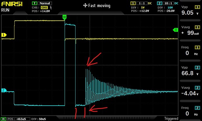
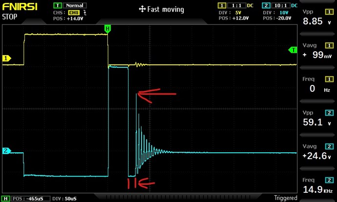
It seems misunderstood that when we are in the presence of different waveforms the way of calculation is different 

Ref: Jagau's Advice for Measurement


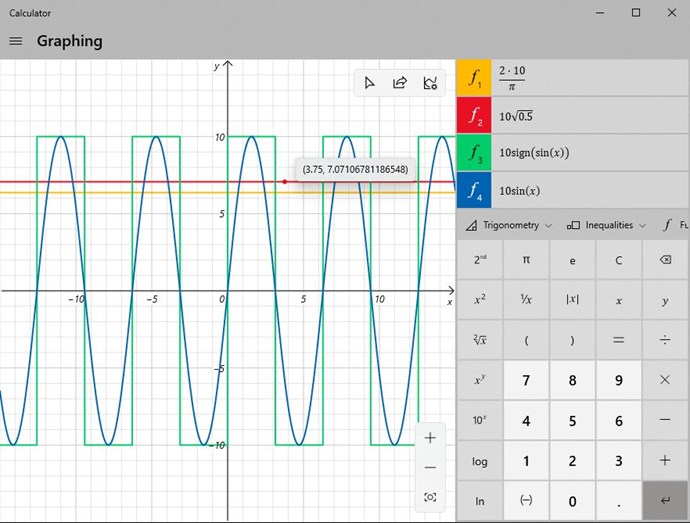
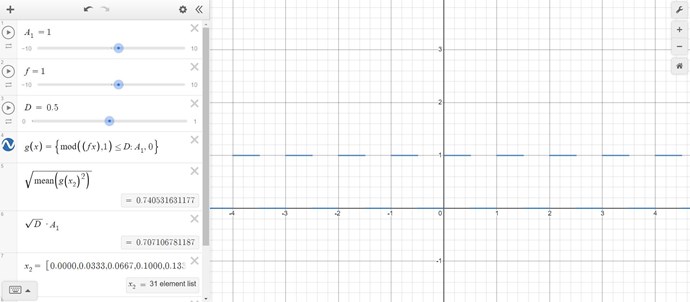
The value: 7.0710678 volts, explained above, comes from the definition of the RMS Value on Positive going Sinusoidal Waveform measurement, or calculation:


To measure the Sine wave, one takes the Peak Voltage, and multiplies by 0.707, in this case, the value of 10 Volts, given above, x 0.707 = 7.07, but with Rounding, the value is cut off, and should be: 7.0710678 volts which Jagau gave us. This means, the value of 0.707 is actually: 0.70710678, again a rounding issue is the difference.

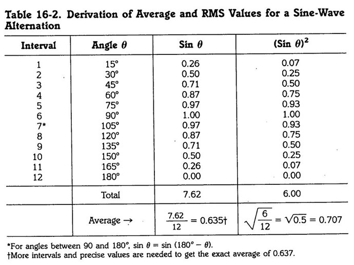
The factor 0.707 for rms value is derived as the square root of the average (mean) of all the squares of the sine values. If we take the sine for each angle in the cycle, square each value, add all the squares, divide by the number of values added to obtain the average square, and then take the square root of this mean value, the answer is 0.707. These Calculations are shown in Table 16-2 for one alternation from 0 to 180°.


Ref: Alternating Voltage and Current.


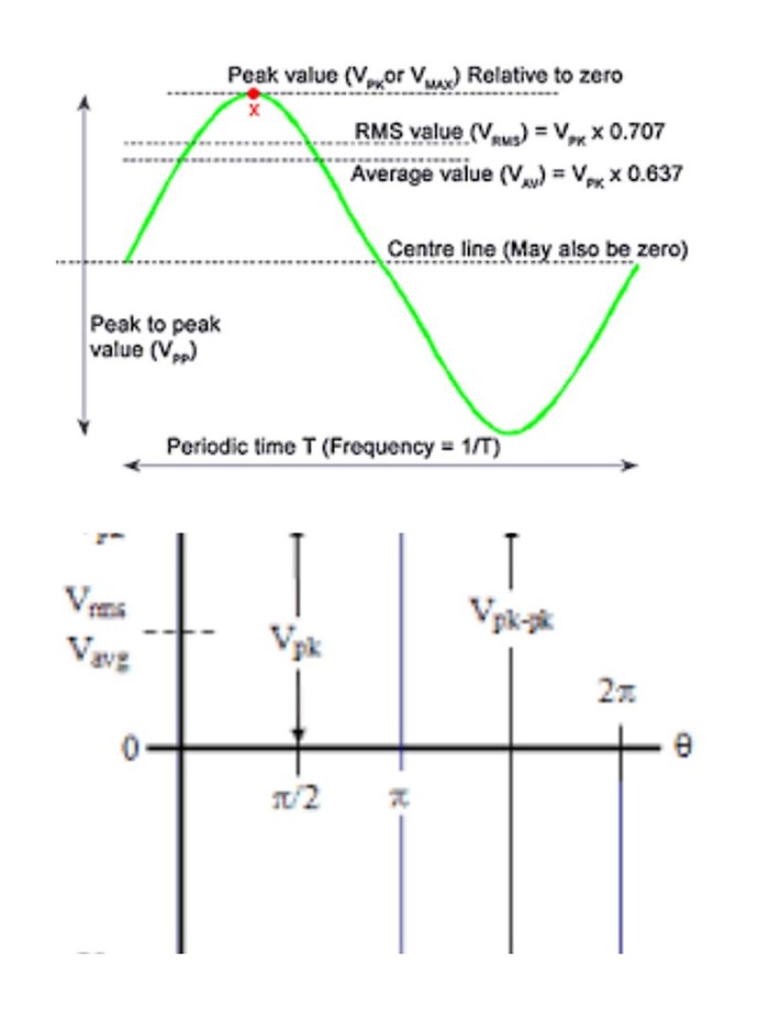
In the above Image, you can see the difference for a Sine Wave, between Average or Mean and RMS. There is a difference of:

  • RMS = 10 Volts x 0.707 = 7.07.
  • Mean = 10 Volts x 0.637 = 6.37.


A reasonable difference of: ≅ 10%

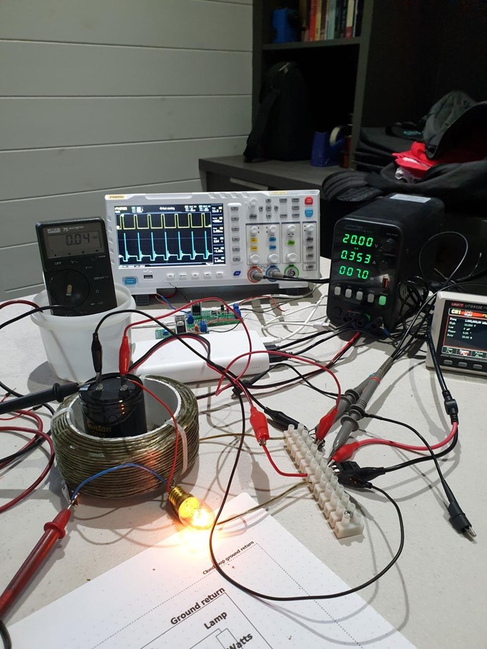
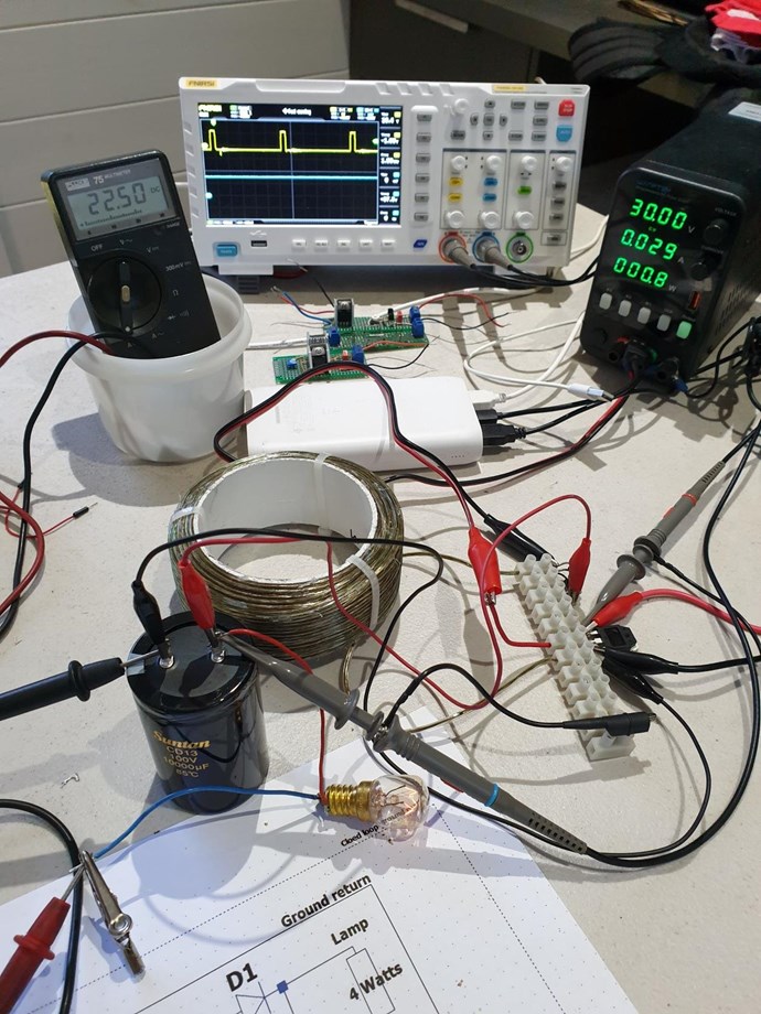
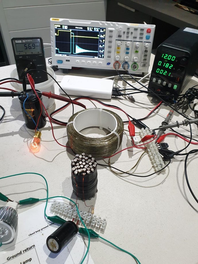
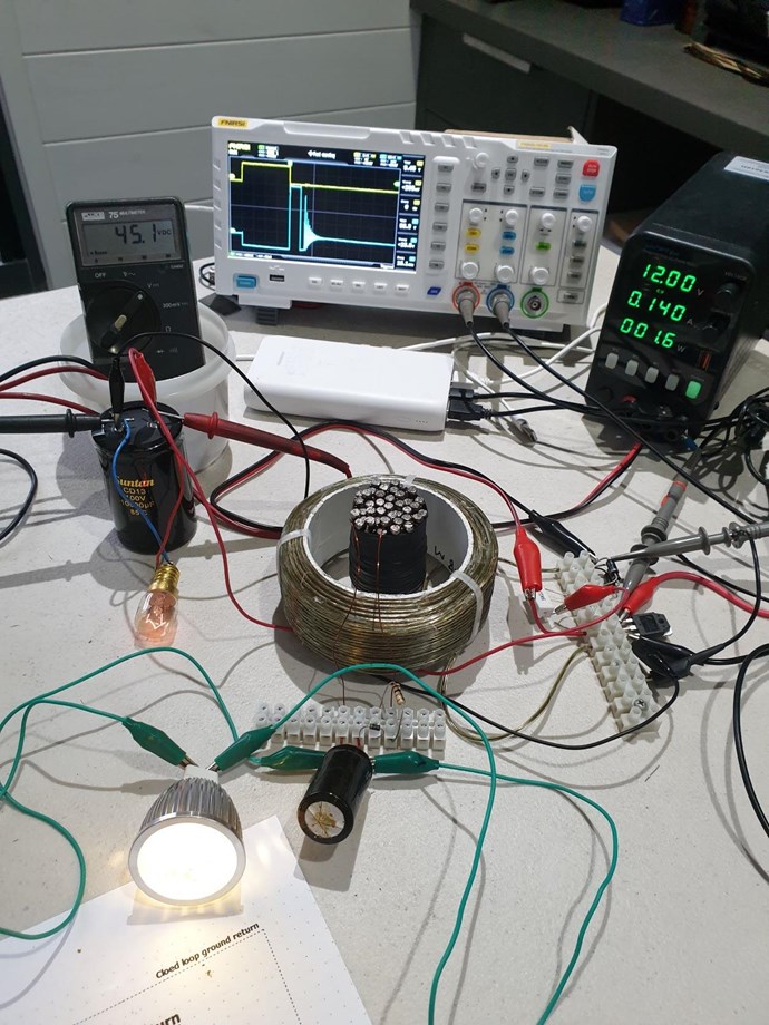
The type of Waveform, and what the Waveform is doing, is important and must be realised to make accurate Measurements! This is all important stuff and even some engineers do not know some of this stuff!

Thank You Jagau and SonOfLuck, great Posts!

Best Wishes,

   Chris

Attached Files

We're Light Years Ahead!
Members Online:
What is a Scalar:

In physics, scalars are physical quantities that are unaffected by changes to a vector space basis. Scalars are often accompanied by units of measurement, as in "10 cm". Examples of scalar quantities are mass, distance, charge, volume, time, speed, and the magnitude of physical vectors in general.

You need to forget the Non-Sense that some spout with out knowing the actual Definition of the word Scalar! Some people talk absolute Bull Sh*t!

The pressure P in the formula P = pgh, pgh is a scalar that tells you the amount of this squashing force per unit area in a fluid.

A Scalar, having both direction and magnitude, can be anything! The Magnetic Field, a Charge moving, yet some Numb Nuts think it means Magic Science!

Message from God:

Hello my children. This is Yahweh, the one true Lord. You have found creation's secret. Now share it peacefully with the world.

Ref: Message from God written inside the Human Genome

God be in my head, and in my thinking.

God be in my eyes, and in my looking.

God be in my mouth, and in my speaking.

Oh, God be in my heart, and in my understanding.

Your Support:

More than anything else, your contributions to this forum are most important! We are trying to actively get all visitors involved, but we do only have a few main contributors, which are very much appreciated! If you would like to see more pages with more detailed experiments and answers, perhaps a contribution of another type maybe possible:

PayPal De-Platformed me!

They REFUSE to tell me why!

We now use Wise!

Donate
Use E-Mail: Chris at aboveunity.com

The content I am sharing is not only unique, but is changing the world as we know it! Please Support Us!

Thank You So Much!

Weeks High Earners:
The great Nikola Tesla:

Ere many generations pass, our machinery will be driven by a power obtainable at any point of the universe. This idea is not novel. Men have been led to it long ago by instinct or reason. It has been expressed in many ways, and in many places, in the history of old and new. We find it in the delightful myth of Antheus, who drives power from the earth; we find it among the subtle speculations of one of your splendid mathematicians, and in many hints and statements of thinkers of the present time. Throughout space there is energy. Is this energy static or kinetic? If static, our hopes are in vain; if kinetic - and this we know it is for certain - then it is a mere question of time when men will succeed in attaching their machinery to the very wheelwork of nature.

Experiments With Alternate Currents Of High Potential And High Frequency (February 1892).

Close