CaptnFalcon's Mr Preva Experiment Replication

  • 212 Views
  • Last Post 14 November 2023
CaptnFalcon posted this 11 November 2023

Hi all,

I believe I have succeeded in replicating the Mr. Preva Experiment, 

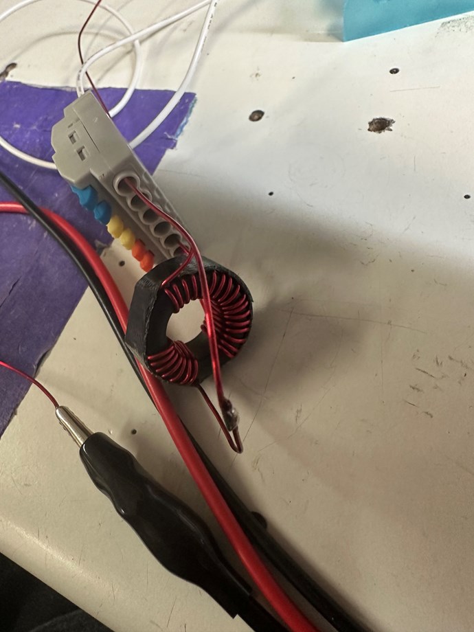
Here is my coil, it has 7 turns on one side and 17 turns on the other,


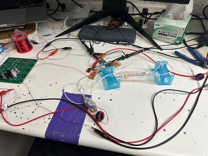
And here is the entire setup, I have it setup almost exactly how Preva's circuit looks,

\


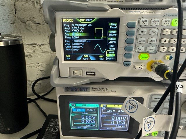
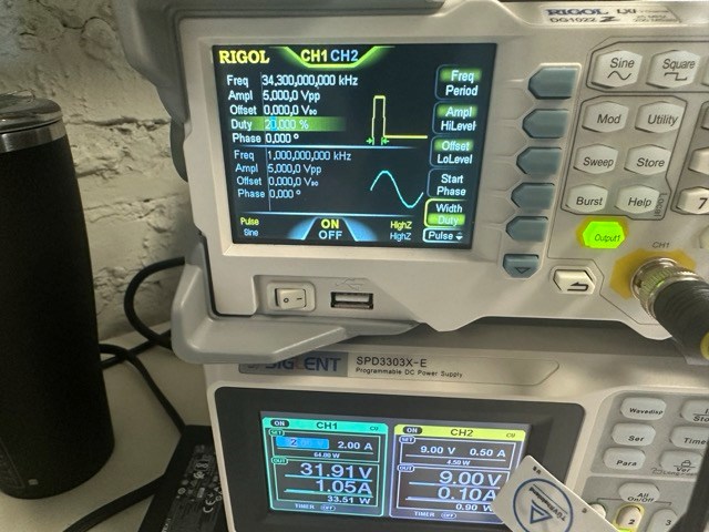
Here is the power supply and the function generator, as well as the O-scope but I don't know if the scope is correct,


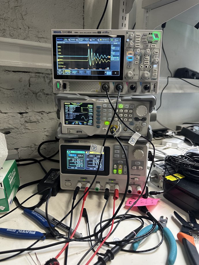
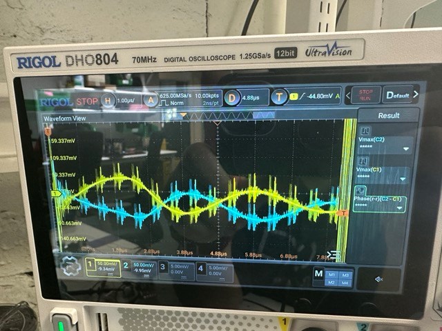
It's hard to see in this image but the frequency is set to a pulse generator at 72.1kHz, and the duty cycle is set to 15%.


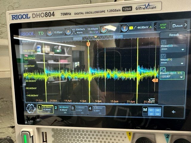
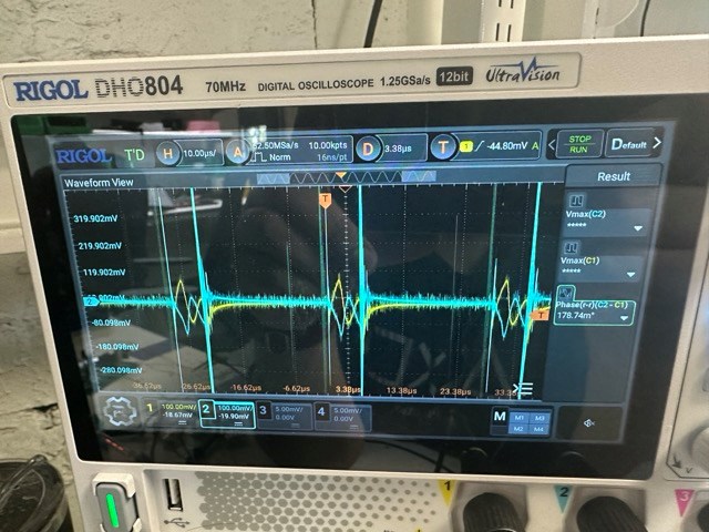
The readings I have on my O-Scope, again I am not sure if they are correct, but the yellow line is going to the 7 turn coil, and the blue line is going to the 17 turn coil, the yellow channel is reading 1.8A V(max), and the blue channel is reading 1.1A V(max), and the Phase Shift is 52deg however it was floating and flipping between 40 - 100 degrees, I am not too sure if I am making the right readings so please DM me and I can make different readings and I'll post it.

Besides me making potentially incorrect readings, here is the loads with the brighter bulb being connected to the yellow probe and the 7 turn coil.


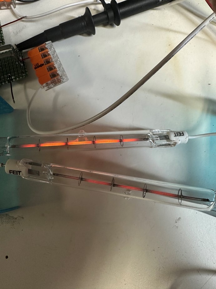
These Bulbs are 500W 120V rated at 8500 lumens.

I found that the phenomena of one bulb being brighter than the other happened at 36kHz and 72kHz and when I went above or below those frequencies the bulbs would dim and be off completely at a certain point above or below, the higher I made the frequency above the 72kHz the dimmer it became, and the bulbs would not be on even well in to the 100kHz range.

Please let me know what I can do to get the same readings everyone else is getting on their scopes without me having to purchase current probes.


Order By: Standard | Newest | Votes
Chris posted this 13 November 2023

Hey CaptnFalcon,

The Mr Preva Experiment is an excellent place to start!

Thanks for sharing! Good Work! I put your Replication, into its own thread, that way, its your Thread and you can post your progress and others can follow.

My Friend, this is good work. If you don't mind me pointing out, I was hoping someone else would, but the Replication should have a Sinusoidal Waveform when in Resonance, each waveform 180 degrees out of phase.


When the Currents measured are approximately 180 degrees out of phase, you have Magnetic Resonance, this is Important, and you will require this effect in experiments on going.

I am happy to help you further your understanding, so please don't give up, this is early days, we have a lot to learn, a lot that is not in any Electrical Engineering Textbooks anywhere!

Electrical Energy is Pumped from Source! Source is the Atom, Charge is the Electron and the Ion, and Current is defined as Charges Flowing at a Rate, where One Ampere is 6.241509 × 10¹⁸ Charges per second, and One Volt is the same number of Charges, but stationary, not moving! One Coulomb is the same, the electric charge delivered by a One Ampere constant Current in one Second.

Thus, the Volt and the Coulomb could quite easily become confused, as one might think they are the same thing.

The Mr Preva Experiment is an excellent place to start and you have nice equipment to study this in great detail! Its just up to you to now study and apply the knowledge gained!

Best Wishes,

   Chris

CaptnFalcon posted this 14 November 2023

Hello, 

Thanks Chris, I thought so, from the other posts that I saw, the wave form for the current is what was seen being 180 degrees shifted.

       However I didn't see any posts of what it looks like zoomed out, again, maybe it is just my scope because of how many points of data it can capture, it being 12bit, maybe I am just able to see more raw data. I am going to take it to one of the O-Scopes that are in my office that are like $50k+ to see it in even more detail.

       Here is what I found on my O-Scope when I adjusted it to a few different values, I want to clarify early that most of the values were fluctuating and it is difficult to get a clear reading for the phase specifically.. 

First New Test:

       Every thing is the same from the original test component wise, I am messing with the values going in to show how the circuit is reacting.

Function Generator at 60% Duty Cycle and Power Supply at 5V


O-Scope Zoomed out looking at the current, Ignore voltage values as I was not concerned about them merely the wave form showing it looking like how the original and all the other replications were looking.


Okay now I going to show it with more voltage going through the circuit, and at lower Duty Cycle due to power supply constraints.

Here is the second set of values for the Function Generator and Power Supply:


And here are a few pictures of what I was seeing from my original post just zoomed out and zoomed in for more clarity on the measured wave forms.


       I played with the Duty cycle and input voltage for about an hour and when I went higher in frequency the noise that you see in the very last picture on the far left side of the screen would shift to the left and in a way cover over and distort the wave form.

       I also did try lower frequencies and it had the same effect as turning the Duty cycle down. It was a bit difficult because I had to turn the voltage down to prevent causing excess current on my Switching FET.

       I think that my scope while very good for what I am using it for, it is not the "best" for this application, and how I am probing current is as well less than Ideal, I am going to go early in the morning tomorrow when I know none of the Engineers will be using the expensive O-scope and I will see if I can get some better pictures of the wave form. 

If there is anything you want me to try let me know, and I'll post the results. 


I wanted to say out loud that this stuff is very fun and that you shouldn't be afraid to blow stuff up (parts that is lol not the equipment). This stuff is super easy to set up, and I am having a lot of fun doing my experiments. Thanks for the encouragement.

Chris posted this 14 November 2023

Hey Cap,

Forget about Duty Cycle and Switching, just use a Sinusoidal Waveform, maybe employ a small Audio Amp for this experiment?

I would work on a single RLC Circuit, and get it in Resonance:


Focus on just the Inductance L, and the Capacitance C, and forget about the Resistance R for the moment. The Circuit has its own Resistance R, and for the mean time does not need to be focused on.

This Circuit, Series LC Resonator will be resonant at the Frequency F, where:


NOTE: Parallel and Series Resonance are different and the differences are not always subtle:

  • Impedance Z is at maximum in a Parallel RLC circuit at Resonance.
  • Impedance Z is at minimum in a Series RLC circuit at Resonance.


There is a lot to learn here, we will help you along!

Best Wishes,

   Chris

We're Light Years Ahead!
Members Online:

No one online at the moment


What is a Scalar:

In physics, scalars are physical quantities that are unaffected by changes to a vector space basis. Scalars are often accompanied by units of measurement, as in "10 cm". Examples of scalar quantities are mass, distance, charge, volume, time, speed, and the magnitude of physical vectors in general.

You need to forget the Non-Sense that some spout with out knowing the actual Definition of the word Scalar! Some people talk absolute Bull Sh*t!

The pressure P in the formula P = pgh, pgh is a scalar that tells you the amount of this squashing force per unit area in a fluid.

A Scalar, having both direction and magnitude, can be anything! The Magnetic Field, a Charge moving, yet some Numb Nuts think it means Magic Science!

Message from God:

Hello my children. This is Yahweh, the one true Lord. You have found creation's secret. Now share it peacefully with the world.

Ref: Message from God written inside the Human Genome

God be in my head, and in my thinking.

God be in my eyes, and in my looking.

God be in my mouth, and in my speaking.

Oh, God be in my heart, and in my understanding.

Your Support:

More than anything else, your contributions to this forum are most important! We are trying to actively get all visitors involved, but we do only have a few main contributors, which are very much appreciated! If you would like to see more pages with more detailed experiments and answers, perhaps a contribution of another type maybe possible:

PayPal De-Platformed me!

They REFUSE to tell me why!

We now use Wise!

Donate
Use E-Mail: Chris at aboveunity.com

The content I am sharing is not only unique, but is changing the world as we know it! Please Support Us!

Thank You So Much!

Weeks High Earners:
The great Nikola Tesla:

Ere many generations pass, our machinery will be driven by a power obtainable at any point of the universe. This idea is not novel. Men have been led to it long ago by instinct or reason. It has been expressed in many ways, and in many places, in the history of old and new. We find it in the delightful myth of Antheus, who drives power from the earth; we find it among the subtle speculations of one of your splendid mathematicians, and in many hints and statements of thinkers of the present time. Throughout space there is energy. Is this energy static or kinetic? If static, our hopes are in vain; if kinetic - and this we know it is for certain - then it is a mere question of time when men will succeed in attaching their machinery to the very wheelwork of nature.

Experiments With Alternate Currents Of High Potential And High Frequency (February 1892).

Close