

This Is a Project I am working on actually for a dual phase PWM with combined analogue and digital features. It is based on an enhanced 8bit MC, the PIC16F785 with specific peripherals, like a dual phase PWM module and two hi speed comparators, which are used for analogue duty cycle adjustment with infinite resolution. This MC can run on different internal and external oscillator sources, up to 20Mhz, the PWM clock is derived from the system clock, theoretical up to a maximum of 2,5Mhz; practically with reasonable resolution i have tested up to 200Khz with this MC. To overcome the limited period resolution I will use an adjustable external oscillator to clock the MC, which in combination with the pre-and post-scaler in software should allow an infinite period resolution over a wide range of frequencies as well. This features I believe will be helpful to drive resonant LCR circuits, using half- or full-bridge switches with the possibility to trigger magnetic resonance. The signals can be configured as free running two phase signal with independent adjustable duty cycles, or as complementary drive signals with programmable deadtime or overlapping. A synchronization feature allows to connect various MC in parallel in order to add more phases if needed.
In a first stage I will build the circuit on stripboard and test to find the appropriated values for the discrete components and work out the source code. For the moment the work and progress will be posted here in Tier II, participation and suggestions are welcome as always. If a useful tool results from this work it will be released as open source. This first schematic is a draft, to be improved while developing and testing is going on. 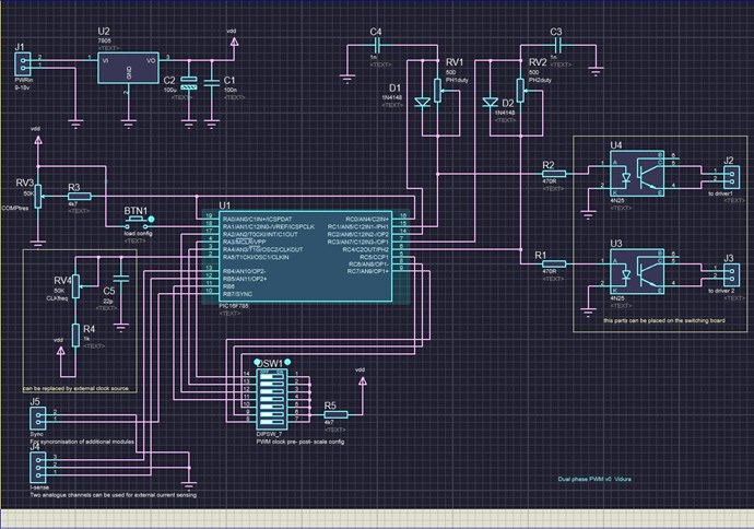
Dual phase PWM
- 1.1K Views
- Last Post 19 September 2019
- Liked by
-

-

-

Some additional data about the basic operation of the device: the components in the rectangle at the right side RV4 R4 C5 are the external adjustable clock for the MC.RV1 D1 C4 makes a sawtooth generator for the timing of phase 1 duty cycle, same as RV2 D2 C3 for phase 2. When the output signal of the respective phase goes hi the capacitor charges up until the comparator reaches the reverence value and terminates the pulse.RV3 R3 are for a coarse adjustment of the reverence voltage for both comparators, this is necessary to set properly the value for different frequency ranges. The Dip switch is to configure the frequency range by system clock dividers and shift value between the phases. With the Sync Signal available on J5 another MC can be synchronized for example to use a synchronous rectifier with certain time delay. On J4 two additional GPIO ports are available for sensing purposes. As attachment the datasheet of the MC:
- Liked by
-
-
Finally i could advance a little in this project, first I have simplified the circuit , reducing it to only the two phase signal source, the other features will be available on the definitive PCB for optional use. Anyway to make the circuit operational a PIC programmer is needed, so also the programmable configurations of the MC can be set up this way, simplifying the basic circuit considerably.
I have built this circuit for first testing:
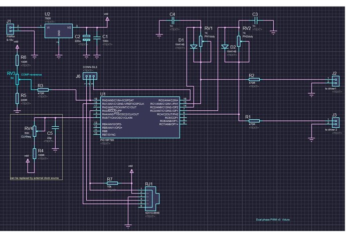
A connector socket for the PIC programmer has been added, and additional(optional) circuitry removed. Some component values might need to be modified to match the required frequency and adjustments ranges.
here a video from the first test:
- Liked by
-
-
-
Hi All,
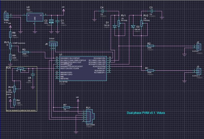
I was working on this project, the PWM works as expected, I am waiting for some components for final adjustments. The concept of the tool is modular, for greatest flexibility. I also added a floating driver power supply, so each switch module is completely decoupled from each other and from the signal source, it can be used as half bridge, H bridge or various floating single switches. Here the updated schematics. I think it can be released soon for public access, when testing is concluded.Here a block diagram for a full bridge setup: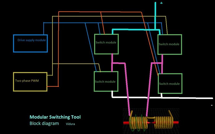
Vidura
- Liked by
-
-
-

-


Hi Vidura
A lot of work in these 3 circuits.I see in the first that you use a high speed IGBT
so these circuits have a max of 50Khz opearion with high amperage.
IGBT work better for high power and low frequency it's one of their highest quality
Jagau
- Liked by
-

-
Hey Jagau, When I started this project the first idea was building a device capable of drive efficiently resonant transformers, with high reactive power circulating. For this I had ordered four 70A rated IGBT. But as in the development surged some ideas ,I think a very useful multipurpose tool is coming out, and in the final PCB design I planned to use screw connectors, so the switching device can be changed according to requirements. PD. I have read some information from SSTC builders Steve Wards and Richie Burnetts, They used successfully IGBTs to drive coils over 200khz using cero current switching. Regards Vidura.
- Liked by
-
-
-
Hi Vidura
Yes, R. Burneett's site has a large amount of information on Tesla coil and particularly on SSTC.
He used, however, mosfets for these H-Bridge.
As he said it's the drivers that are really critical in this type of use. He is a power semiconductor engineer. for I.R. and he is very knowledgeable. One of these last circuits in H-Bridge
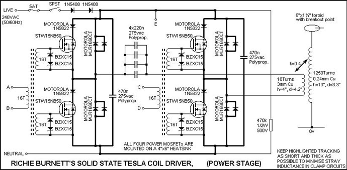
It's very informative site: http://www.richieburnett.co.uk/tesla.shtml
Jagau
- Liked by
-
-
-
-

- and 1 others
Hi Jagau Yes a very Informative site, I have already experimented with this circuit, the gate drive transformer is good, but only for a limited frequency and duty cycle range, that's why I changed to the optical isolating drivers. And you are certainly correct with the current and frequency behaviour of MOSFET and IGBT. What I referred to is more an exception, in the later hi power versions of the SSTC some builders employed IGBTs, for the higher current capability, and if correctly tuned and switched they run cold up to quite high frequencies. I think it is on Steve Wards site where this device can be found, he's not an engineer, only started from zero , and after years of experiments his work reached really a high technical level. For the moment I am waiting for the optical drivers and some more components for this project.The supply is a little difficult and limited in my location, but I know this also happens in other places, so it's a good thing to keep the things simple, and if possible use widely available parts. Vidura
- Liked by
-
-
Hi Vidura
yes you made me discover the site steve ward that I did not know thank you.
It gives an interesting idea on how to use bipolar TVS on his IBGT bridge, very interesting circut too.
Jagau
- Liked by
-
-
Hello Friends,
I have been working on the Switching device this days, supposedly it should be finished for testing, but I had more work as expected, and some details on the driver power supply to resolve. Now almost finished for final assembly and tests of the connected modules. I'm really happy with the PWM module, as it behaves as expected, very intuitive with easy handling of a couple of potentiometers for frequency and duty cycle adjustment. A time ago I have used a 555 pwm circuit for bucking coil and mr. preva tipe experiments, I noted the benefits of this simple way of control, as I could find the sweet spot of the devices in very short time. Although there where some stability problems and glitches eventually. Now with this new device I think I can really combine the advantage of analogue control features with the flexibility and stability of a microcontroller. Here the latest progress, the driver supply module for four switching modules :
And here a Switch modul with handcrafted PCB:
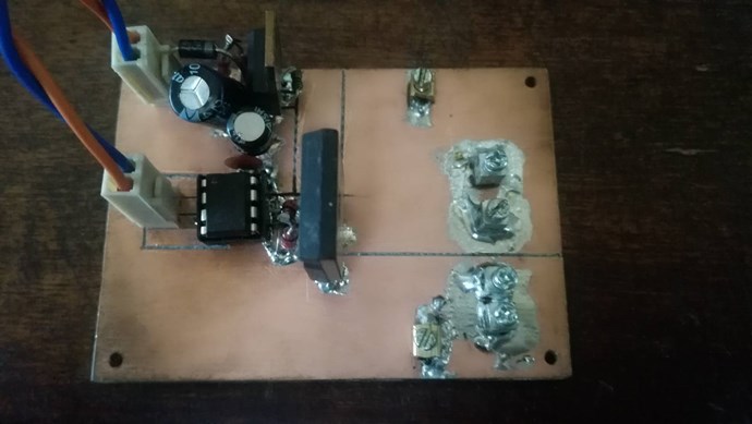
It is dual layer with wide powerplanes, the TVS can be mounted in the screw connectors, as required.
Soon I will post test results, and revised schematics.
Vidura
- Liked by
-
-

@All,
Vidura is on the right track here! PCB with logic in built to handle complex things for you, make things simple!
Of course, in the case of The MEG Team, a TVS is a Switch. That's what it does. Because it is placed Across one of the Output Coils, at a particular Voltage, the Coil becomes Loaded by the TVS and the On Resistance is the load. However, a TVS has a bunch of limitations!
The Experimenters here could learn a lot from Virura's work!
Thank You for sharing Vidura!
Chris
- Liked by
-
-
-
-
Hey Friends, i can tell you that prototyping this stuff can be tricky!
But finally a good advance is made, I could make a first test with some modules connected together. I was very nicely surprised by the optical drivers, they perform much better than I had expected, it's still without load, just a switching test, here the mess on my bench:
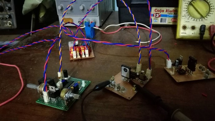
And the scope shots:
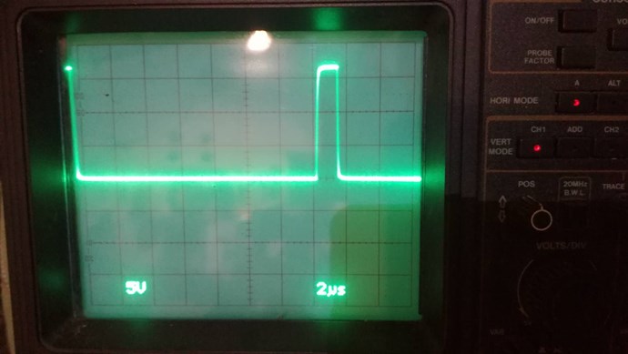
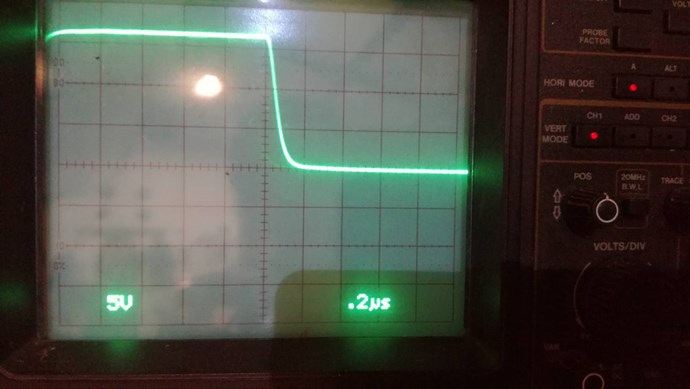
the driver voltage regulator is set for 17V, but the A3120 drivers can handle up to 30V, if the switch can withstand it. The Switching modules with the driver power supply can also be fed with signals from Arduino, as they work completely floating.
I wanted to anticipate that I will post the revised schematics and firmware here in this thread for those who want to build and test some modules, and I have planned to make the modules available for order, for those who would like to purchase readymade devices(part of the profit will return to support the Forum)
Vidura
- Liked by
-
-
-
-
Hey Vidura,
This is absolutely the most important thing to have in ones Took Kit!
A Reliable Flexible Switching System!
There is more value in this than most other equipment! Scope, well most cheap scopes these days are very good for what we need! Cheap DMM's pretty good, you get the idea!
I so wish others would contribute to this very important area! There are others very much more knowledgeable than myself when dealing in this field!
Chris
- Liked by
-
-
-
-
Some tests with a half bridge already done, it works quite well, some minor details to fix on the frequency adjustment, next week the apropiate potentiometers will arrive, also the dip switches for some basic settings without using programmer, so I think I'm close to release the Tool. A issue happened when I made a test with a POC coil shorting , when I blow a 600v rated IGBT with a input of only 6 volts, I found the Varistor was rated to high for the device, as there is no unified coding of values on this devices ,care has been taken, always doublecheck the datasheet!
@ Chris, for making public this work should I change the category of the thread to a public section, or better start a new one?
VIDURA.
- Liked by
-
-
-
Hey Vidura,
My friend, its up to you, but yes if you want to change the category of this thread tp public, maybe select hardware thread of what ever you feel best, or make a new thread. Its up to you my friend.
Chris
- Liked by
-
Hi friends from the builders club.
As the modular switching tool will be ready for ordering in august when I will have the PCBs and some more materials, I will post here for the Members of Tier II the production files and source code. So you have the possibility to order some boards by your own and build some of this modules if you are interested. To load the code on the MCs you will need a PIC programmer, I suggest the PICkit3, which is a mature product and can be acquired at an affordable price from Microchip. For programming I used the freeware available on the website, as the programs are short and simple ,it is sufficient for the job.The driver power supply is corrected regarding the interference issue and the modules are working fine. Any question just PM me for assistance.
VIDURA.
- Liked by
-
-
-
-

Hello Friends.
I have attached in the previous Post the latest production files of the Powerswitchboards and the driverpowersupply, with some minor corrections in vías and some adjustments.
regards Vidura.
- Liked by
-
-
-
Hey CD I have changed the erroneous file, it is ok now. If you need help for building the circuits contact me. Vidura.
- Liked by
-
-
-
-


Past Visitors: 0 | Live Visitors: 0
3D globe widget by: Chris Sykes
In physics, scalars are physical quantities that are unaffected by changes to a vector space basis. Scalars are often accompanied by units of measurement, as in "10 cm". Examples of scalar quantities are mass, distance, charge, volume, time, speed, and the magnitude of physical vectors in general.
You need to forget the Non-Sense that some spout with out knowing the actual Definition of the word Scalar! Some people talk absolute Bull Sh*t!
The pressure P in the formula P = pgh, pgh is a scalar that tells you the amount of this squashing force per unit area in a fluid.
A Scalar, having both direction and magnitude, can be anything! The Magnetic Field, a Charge moving, yet some Numb Nuts think it means Magic Science!
Hello my children. This is Yahweh, the one true Lord. You have found creation's secret. Now share it peacefully with the world.
Ref: Message from God written inside the Human Genome
God be in my head, and in my thinking.
God be in my eyes, and in my looking.
God be in my mouth, and in my speaking.
Oh, God be in my heart, and in my understanding.
We love and trust in our Lord, Jesus Christ of Nazareth!

More than anything else, your contributions to this forum are most important! We are trying to actively get all visitors involved, but we do only have a few main contributors, which are very much appreciated! If you would like to see more pages with more detailed experiments and answers, perhaps a contribution of another type maybe possible:
They REFUSE to tell me why!
The content I am sharing is not only unique, but is changing the world as we know it! Please Support Us!
Thank You So Much!
-
Chris
110
-
GuruNandan 50
-
ElectroMike 34
-
 AETHERIC_MIND
30
AETHERIC_MIND
30
-
 FringeIdeas
30
FringeIdeas
30


Ere many generations pass, our machinery will be driven by a power obtainable at any point of the universe. This idea is not novel. Men have been led to it long ago by instinct or reason. It has been expressed in many ways, and in many places, in the history of old and new. We find it in the delightful myth of Antheus, who drives power from the earth; we find it among the subtle speculations of one of your splendid mathematicians, and in many hints and statements of thinkers of the present time. Throughout space there is energy. Is this energy static or kinetic? If static, our hopes are in vain; if kinetic - and this we know it is for certain - then it is a mere question of time when men will succeed in attaching their machinery to the very wheelwork of nature.
Experiments With Alternate Currents Of High Potential And High Frequency (February 1892).
