Ferrite at work

  • Topic Is Sticky
  • 12K Views
  • Last Post 13 December 2020
Jagau posted this 12 September 2020

An easy to assemble circuit that works, I have tried it myself and it is stable and functional.

This circuit is not from me it is from a Russian researcher who introduces himself under the nick name of "not a square" in russian  'Не квадрат'' 'on this website you can talk to him.
https://strannik-2.ru/index.php/forum/prakticheskaya-elektronika/220-u-menya-interesnaya-skhema?start=1485

The circuit has been working for 5 days now and the voltage is very stable. Here is the circuit:


I admit that I am happy with the result and that the ferrite fuel is doing its job. This circuit deserves to be studied and developed.

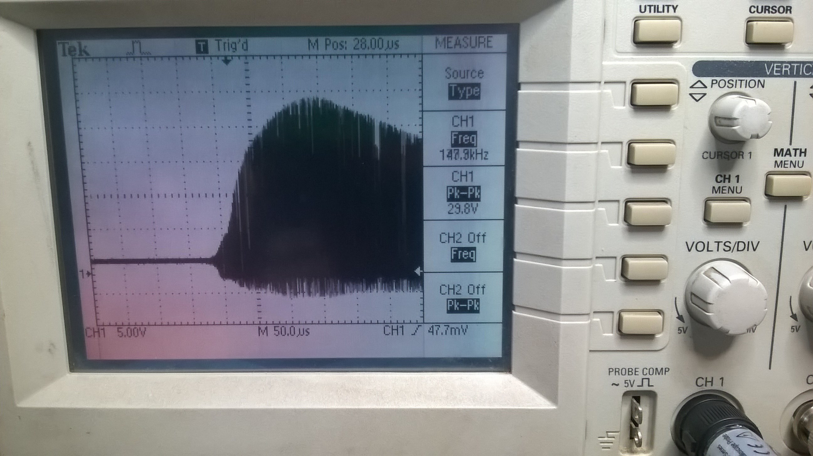
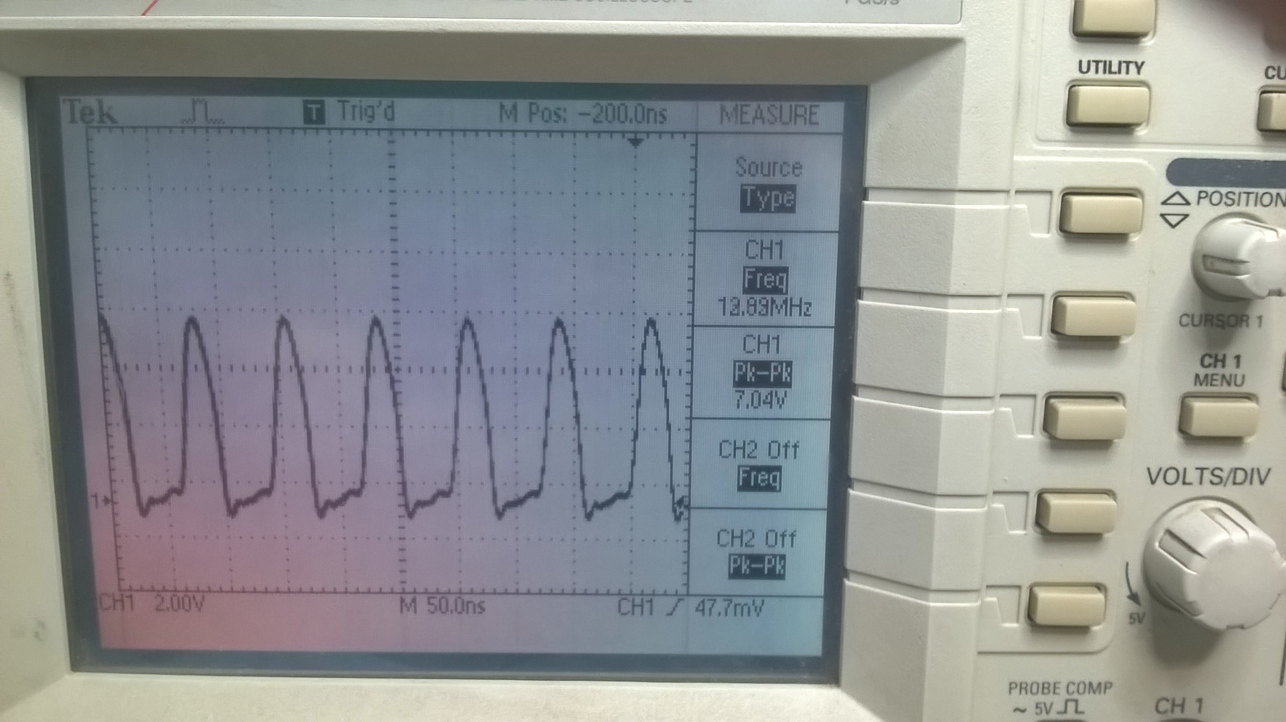
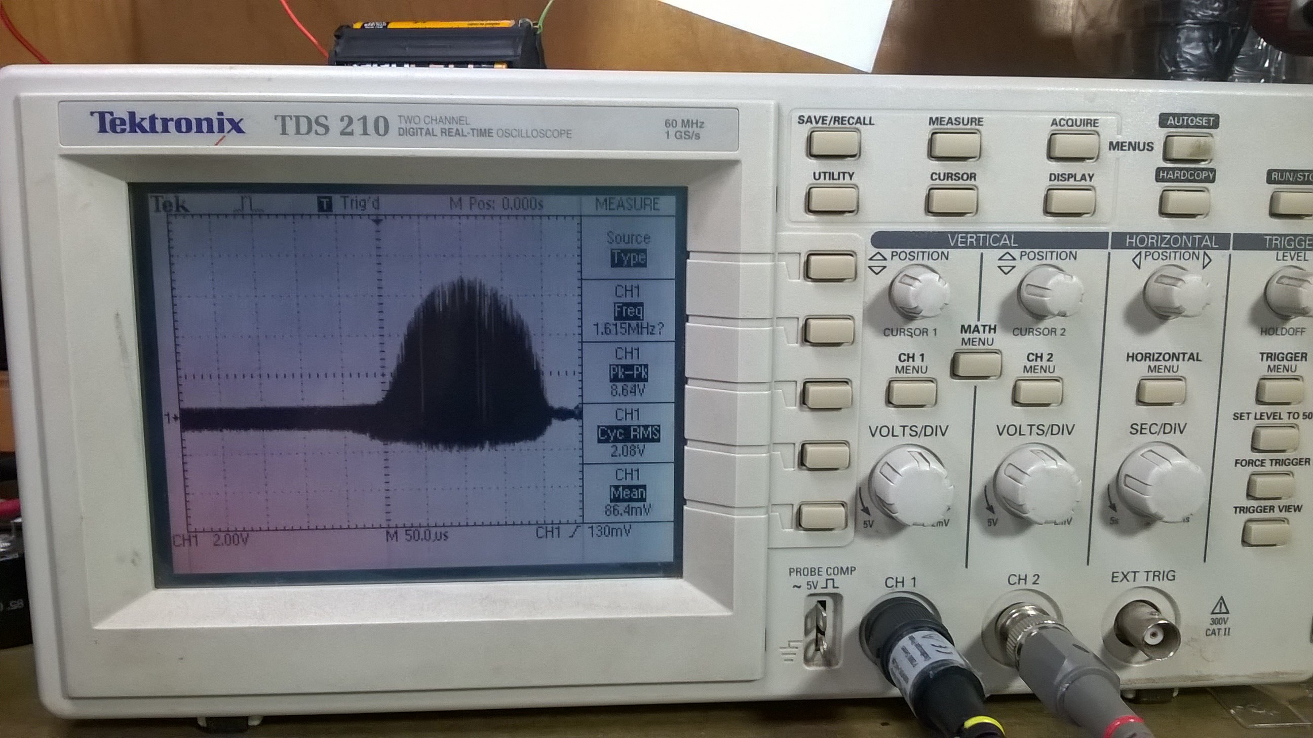
A view of the oscilloscope on the collector

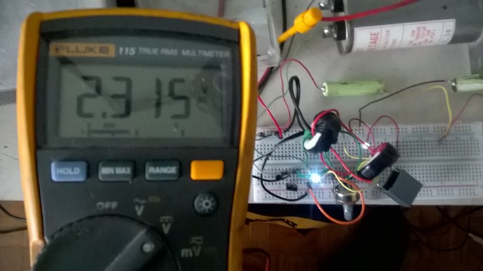
I started at 2.3 volts and now after 5 days the circuit is stabilized at 2.457 volts


Jagau

Order By: Standard | Newest | Votes
Jagau posted this 12 September 2020

Hi all

If you make the circuit, you don't need the 0.5 capacitor to connect the 1 turn coil to itself.
I also had to adapt the capacitor from 5uf to 1.8uf unpolarized with low ESR
I also spoke to the author of this circuit, he told me he would come to register on here.


Let’s welcome it as aboveunity.com can do.


Jagau

Chris posted this 13 September 2020

Hey Augenblick

This is perhaps harder to follow than the original?


Best wishes, stay safe and well My Friend,

   Chris


Jagau posted this 13 September 2020

Good morning all

Thanks Chris for your help.

I did in schematic with Spice while respecting the wire colors and the start and end of the wires on each of the 2 ferrites.


A spice reproduction of the author's original drawing.


As I said in a previous post, I modified the circuit a little so that the battery charge increases more quickly. From the first day until today (fifth day) the load has stabilized more than it was at the beginning while still operating the circuit and with the two LEDs on.


Modification I made fromoriginal circuit.
I took off the cap. 0.5 uf and connect the loop of 1 single turn without the cap. Adjusted the capacitor from 5uf to 1.8uf which gave me a very quick increase in circuit performance.

I made a second circuit with a TV ferrite that works great too.

Am experimenting with this circuit without any battery, only with preloaded caps and the preliminary results are very good

hope this help


Jagau

Attached Files

Jagau posted this 13 September 2020

i augenblick

Yes the polarities (phase) of the coils are very important.
Follow the color of the wires as I added on the shematic.
Identifying your coils with start and end marks respecting the place where they are located on the ferrite will be easier.
Need help do not hesitate to ask.

At the end of the fifth day both systems are still working very well, I think the ferrite fuel is doing its job, more scopeshot to come


Jagau

Nekvadrat posted this 14 September 2020

 с этого начиналось: 

...подключил к подсевшему аккумулятору (1,18В)...напряжение поднялось до 1,236 - держится несколько часов

Изображение

Chris posted this 14 September 2020

it started from this:


Добро пожаловать, Неквадрат,

Спасибо, что поделились!

С наилучшими пожеланиями, оставайся в безопасности, мой друг,

Крис


Welcome Nekvadrat,

Thank You for Sharing!

@Augenblick

This thread should be marked AU then?


I agree, done, if needed we can revert.

Best wishes, stay safe and well My Friend,

   Chris

Nekvadrat posted this 14 September 2020

Jagau posted this 14 September 2020

Привет, Неквадрат
Я очень горжусь тем, что вы здесь, на этом форуме, добро пожаловать.
Я верю, что все присутствующие смогут оценить ваш проект, потому что только вы его автор.

Я еще раз вернусь к информации, которой вы только что поделились.
с большим интересом, большое спасибо за то, что вы здесь.

P.S. На шестой день две системы все еще очень стабильны и функциональны, напряжение не падает, как предсказал Неквадрат. Да, я тоже верю этому А.У.
Ягау


Hello Nekvadrat
I am very proud that you are here in this forum, and welcome.
I believe that everyone present will be able to appreciate your project, because only you are its author.

I will come back to the information you just shared.
with great interest, thank you very much for being here.

P.S. On the sixth day, the two systems are still very stable and functional, the voltage does not drop as Nekvadrat predicted. Yes, I also believe this A.U.

Jagau

Jagau posted this 14 September 2020

The circuit I did on Spice is the one to try for now and it's the one that works.
There are only 6 coils in this configuration and the sixth coil is not a coil, it is only a 1 turn winding between the two ferrites, so the circuit I have on my table is exactly as done with spice.


As for the two LEDs, with the start of an analysis of the circuit that has not been completed, they act as a switch and not as a load.
As I could see it with my oscilloscope, the circuit does not saturate well on the contrary it consumes almost nothing and moreover it recharges the battery in another time of the oscillation.
There is interaction between the two ferrites in a back and forth movement like a swing that comes and goes to make an image.


As you may have noticed Nekvadrat made some additional modifications to the product circuit at the start.
I will make the modifications as he proposes with another assembly and I will communicate the results.


@Nekvadrat, don't hesitate to take us back when we make mistakes, I think your comments will be greatly appreciated

@Nekvadrat, не стесняйтесь возвращать нас, когда мы делаем ошибки, я думаю, что ваши комментарии будут очень благодарны

Jagau

Jagau posted this 14 September 2020

Hi all

A picture is worth a thousand words
The direction of the windings is very important
I took a photo, take a good look at the start and end of each coil.

As you can see the first coil at the top,the white one is a bifiliary winding (2 wires)


Above and below very important, adjust the pot of 100k until an increase in the voltage of the battery.
At the beginning the leds are flashing it's good you have let the system stabilize and you are there.
Jagau

thaelin posted this 15 September 2020

Здравствуйте: Поскольку Есть много рисунков, я хотел бы идти вперед с тем, который вы даты, как 14.1.2013. Можете ли вы сказать мне, сколько жарких используется и какие ветры рассчитывает для каждого, чтобы не иметь путаницы. Спасибо и теплый прием. таелин

Nekvadrat posted this 15 September 2020

...просто соберите по рисунку, дальше - нет предела усовершенствованию........

Nekvadrat posted this 15 September 2020

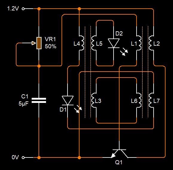
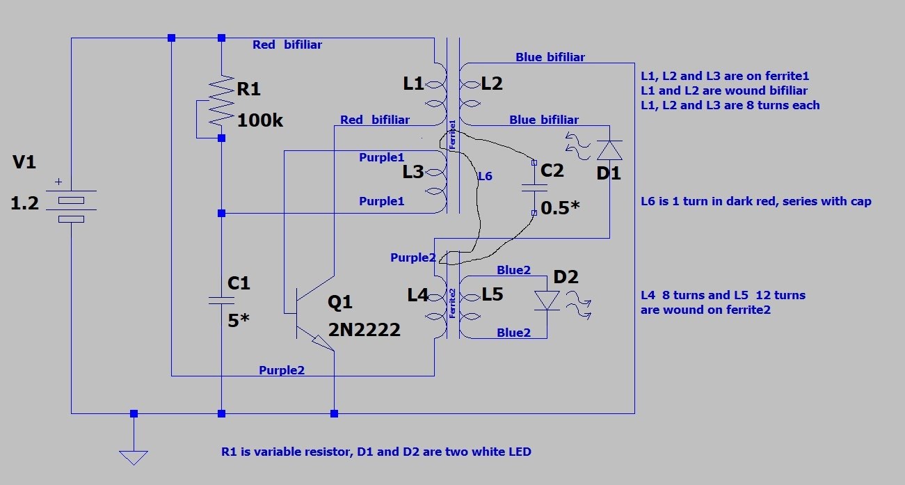
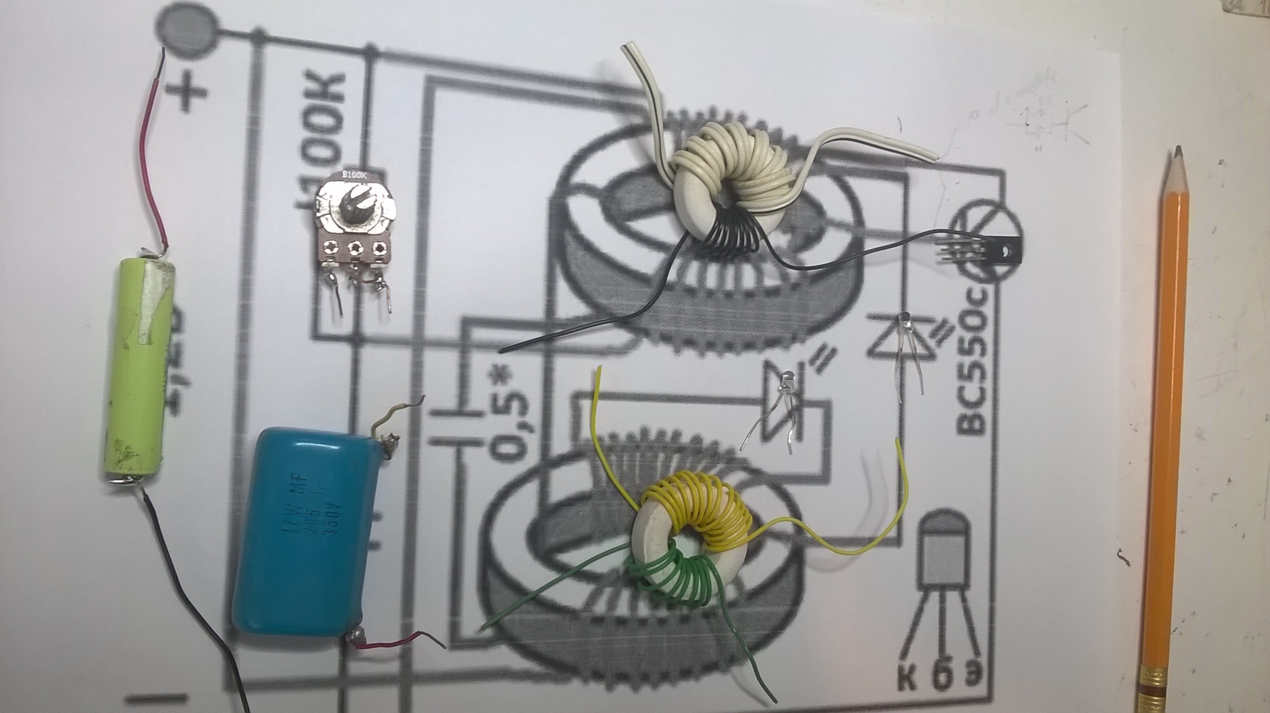
схема довольно интересна и имеет перспективы к развитию...

Vidura posted this 15 September 2020

Hi Nekvadrat, welcome on the AU forum. Have you had some success replacing the battery by capacitors? Regards Vidura.

Jagau posted this 15 September 2020

 HI all

A recap is in order
When I started this post I asked '' Nekvadrat '' for permission to bring here on the Aboveunity.com forum the drawing which appears at the beginning of the thread, it is the one I had at this moment in my files.
He kindly replied that there was no objection to my bringing it here.
 

Following the invitation of Nekvedrat on the forum, I am very happy with his coming, I learned like all of you that there were 2 other drawings that nekvadrat kindly provided to us.
There is an evolution in the first drawing which will lead us to evolve as nekvadrat did, it must have taken hundreds of hours, and I thank him for letting us know about its evolution.

In order to avoid confusion in the 3 drawings, for the moment I would like everyone to focus on the first drawing provided in order to understand it and to understand all the nuances of this first drawings.


Having some experience in building such a circuit it is much better to start with things that can be understood and explained.


I can tell you seriously that the first drawing works and I start to understand the nuances


We can then evolve with the last two drawings as nekvadrat did and ask for his help without constantly bothering him with trivial questions.


This is what I had in mind when I started this thread, thank you for your understanding


Jagau

Wistiti posted this 15 September 2020

Agreed Jagau. I will try the first one you share and post my results when I will have it working.

Thank you for your support and contributions!

Wistiti posted this 15 September 2020

Hi team!

Here is my replication of the first circuit Jagau have shared with us. 


I know many things is different cause i have to use the things i alredy have on hand...

Instead of a battery i use a Maxwell Ultracap of 2000f (i know it's big!)


I have to said i have to inverse the bifilar connection to make it start.

Will see how long it will run...


Hope to see some other's replication!


Attached Files

Jagau posted this 15 September 2020

Hi wistiti

Well done wistiti

Will follow your result with great interest

Jagau

Vidura posted this 16 September 2020

Hey friends, I have also given a try to the circuit yesterday, like wistiti I also had to swap the terminal of a coil compared with the drawing (the one on the base of the transistor) to make it oscillate. An old NiMH battery started at 1 v have raised to 1.15v in a few hours. Replacing the battery with electrolyte capacitors @1410uF it doesn't sustaining. Vidura.

Jagau posted this 16 September 2020

Hi vidura

 Do you use straight ferrites like wistiti or round ferrites, because the design is made accordingly of round ferrite (closed magnetic path). But for you too it works well done.

A battery is an active element (ionized chemical product), it does not charge in the same way as a capacitor which is a passive element (displacement current between two plates)
To charge a capacitor, i think, this is not the right setup.
But it's good to try to experiment, all experimentation is good to do.


P.S, almost a week already with my setup and the voltage has not dropped by 1millivolt, the system is self-sustaining, the oscillator is working and the 2 LEDs are on.
Jagau

L0stf0x posted this 16 September 2020

Hello team, I also had a fast try to it like my friends Wistiti and Vidura..  also had to reverse polarity. 

I have no idea what the LEDs should do, but they blinking.

The capacitor is charging somehow.. I hope I ll find time to experiment more later today and understand how it works.

Wistiti posted this 16 September 2020

Nice job my friend!! Just to be sure, witch coil do you reverse the polarity?

Thanks for sharing!

Jagau posted this 16 September 2020

Hi LOstfox

It's really good to see that it works for you too.
As for the leds blinking, I noticed the same thing as you last Thursday.
The 100k should be set to have minimum voltage drop at startup and I have noticed that when the battery reaches a certain level the frequency of flashes decreases and only a very slow flash is surely a feature of this circuit. I have already built 5 different circuits with the drawing that Nekvedrat provided us.

Well done it seems that it also charges a capacitor that keeps us informed of your results, with the whole team we will surely achieve a good result.
thanks for sharing.

I will invite others to share and experiment, don't be shy this is the first selfrunner I see that works without voltage lost.

Other future observations on this selfrunner.

Jagau

L0stf0x posted this 16 September 2020

Hey my friend Wistiti! Hey Jagau, thanks for sharing! Sure! I changed the polarity of the upper purple coil (at original drawing), the one that goes to base of transistor. I also burned 3-4 transistors and several LEDs while I was playing using battery with it..

The super capacitor is 10 farad and started with 0.57V and went to 1.764V in few hours and stayed there.. and the LED was blinking faster. I haven't played with 1.5uf capacitor yet.

Another try was with a LiIon battery at 3.95V and when I was connecting earth (red cable) at the negative lead of the LED that is connected to both cores (Led was removed.. positive lead was open) the voltage jumped to 4.40V. Strange eh?

Edit: my earth connection is directly connected to a copper rod buried 3 meters in my garden. It is not coming from the main house ground grid connection.

This need more time to investigate!

Jagau posted this 16 September 2020

hi lost

 Yes I think the 4.4v is the voltage that re-ignites the system, that's why I think he installed a 4.7 volts zener diode in his last circuit to regulate the system (to be investigated)


This circuit like you is really efficient when it is well adjusted, it consumes almost nothing and gives a lot, like you my I'm investigating and it's fascinating isn't it?


Jagau

L0stf0x posted this 16 September 2020

Video is ok now sorry about it! Sure Jagau this circuit is very interesting ! I wish I could understand how it works! but I have no idea yet!

Wistiti posted this 16 September 2020

Nice video my freind L0stf0x!

When the time permit, would you draw a schematic of your circuit using earth ground? im not sure i understand where it is connected...?


Thank you and happy to see you back!

YoElMiCrO posted this 16 September 2020

Hi all.

I join the replica of the circuit, also its study.
Today later without fail I do it, thanks for sharing it.
As soon as I have an answer about how it works I share it
in this same thread.

Thanks in advance.

YoElMiCrO.

Jagau posted this 16 September 2020

 Hi yo

 Thank you for your presence on "ferrite at work"
I very much appreciate your comments knowing in advance that they will be very relevant and informative.


Jagau


kalleFin posted this 16 September 2020


Hello to everyone!

I took my shot at this wonderful project. Thanks to everyone who is involved in this. I greatly appreciate your openness. My circuit is running currently for the 25th hour using two AAA alkaline batteries in series. That was what I had on hand when I started this experiment. At first I wondered if this really could work as I witnessed the batteries lose voltage, but as soon as Jagau described the tuning, I got to the system up so that the batteries seemed to be regaining some of their lost charge. Now the charge seems to have stabilized after about 24 hours of climbing.

My build uses large ferrite cores. I was planning on using them to power a Barbosa & Leal type of set up. Actually this system has some resemblence to their designs, in my humble opinion.

Thank you Chris for this opportunity to share and collaborate and reach beyond. You have been a great inspiration!

Kalle


Jagau posted this 16 September 2020

Hello kalleVery nice replica I appreciate your sharing. When you will be able to have rechargeable batteries you will see a big improvement, I have the same configuration as you with 2 small 1.2 volt AAA batteries in series, I find the system to be much more stable at this voltage. Once again a great success.

Yes Chris is surely very proud of his team that I believe in a spirit of cooperation, this forum is a treasure

P.S. My friends, Don't forget to thank Nekvadrat for giving us the opportunity, He is the inventor of this circuit

So THANK YOU NEKVADRAT


Jagau

Wistiti posted this 16 September 2020

Yes, the first thank's goes to Nekvadrat!

Im curious if we can pump it up at a higher voltage, something like 12v or higher...

A really basic and fun circuit to explore.

thaelin posted this 16 September 2020

My first try was a flop. Did the fix and it runs. Has a very high cycle so both led's are bright. But is an amp eater. Does use a 3055 tho and needs to be changed to a smaller transistor. Proof of concept passed with colors.

Will have a better layout soon as back from 4 day work trip. Will need to figure out how to post pics/vids to show how it looks.

thay

and:   tried to run on 3v and will not. Think transistor trigger circuit is too much.

L0stf0x posted this 16 September 2020

Wistiti sorry I missed details.. I repeated the earth effect, to make sure its repeatable.. and it is! Here is where I connect the earth.

You don't need to remove any LED. And do not reverse the coil.. just use the original circuit on that. The LEDS are both off. But the voltage at battery goes high immediately when I connect the earth there. I got a new video but its nothing different than my last one. Same effect. Strange indeed! 

Edit: I think without the Led is working better.

Jagau posted this 16 September 2020

Hey thaelin
I know it's not often easy, maybe just a little phasing error and you'll get it, just keep a small 1.2 volts rechargeable at the start it will be easier.

A very good thread that Chris wrote a few times ago but which will surely help you avoid problems with this circuit. Look to the right of your screen, link is right there :   Some coils buck some dont, 


@ lostfox
wow you discovered a new way with an external mass as indicated, it's good let's keep experimenting.


Jagau

YoElMiCrO posted this 17 September 2020

Hi all.

@Jagau.

I still do not test the circuit, but doing
an analysis by inspection of the same I have
more or less an idea of how it works.
Looking at the oscilloscope image it is evident
What is related to the phenomenon of the curve
negative magnetic permeability of the material
used in conjunction with your way of working.
If you see the video that Zanzal from Avalon uploaded you will see
their similarity.
This weekend I will replicate the circuit without fail,
also that of Loz, to study it better.

Thanks to Nekvadra for sharing.

Thank you all in advance.

YoElMiCrO.

Wistiti posted this 17 September 2020

Hi team.

I have restart the experiment cause my transistor fail (cheap one fron Ebay...) I change it for a 2n2222 and rewind on a toroid core.


After a night running on the ultra capacitor, i see a little discharge on the cap. Maybe i have to have a better tuning.

Experimenting will continue...

Jagau posted this 17 September 2020

Hi all


An update
I started this schematic last Thursday 10th with 2.325V and it has been now a week since the circuit works and the voltage is today at 2.54V.
The 2 leds are on and the oscillator is still working.
The nominal voltage of each of the batteries are normally 1.2V, i use 2 of them.
So these are very good results considering that the syteme run 24 hours a day.
Some waveforms taken this morning on the collector of the BT139 is the transistor I use

Take note that on the second photo it is when we stretch the first to see what is inside.


Jagau

Atti posted this 17 September 2020

Hi all.

Should both LEDs flash or just one?

Jagau posted this 17 September 2020

Hi atti
At the beginning the 2 leds flash but when the battery charge becomes stonger,

a little flicker is sent.


did you manage to do it? if so, well done


Jagau

Atti posted this 17 September 2020

Only one LED flashes. There will probably be setup issues. It has been operating for three hours without a voltage drop. There is no voltage increase yet. I will perform more tests as my time allows. (my first opinion on the setup: it's like a battery desulfator)

Jagau posted this 17 September 2020

Try to reverse the last coil at the bottom
probably just a phase error.
For battery desulphation there are more efficient systems.
It works for the author and me and also several others just a few adjustments you will get there.
Jagau

Nekvadrat posted this 18 September 2020

Atti возьмите многожильный провод и соедините "восьмеркой" два тора. От оборота "восмерки" в ту или иную сторону - зависит многое...

L0stf0x posted this 18 September 2020

Well I am still puzzled about the circuit. I tried to charge the cap again using a 2n3904. But with 2n3904 It doesn't want to charge the capacitor. But with BD437 "most times" the cap is charging again. It looks that every movement of ferrites gives different results. So my opinion until now is that the tuning has to be done not so much with the trimmer rather with the position of ferrites and their common loop somehow.

Jagau posted this 18 September 2020

Yes you are right Lostfox, I have built a few of them and they all work differently.
Even on a certain model of breadboard it did not work, too much stray capacitance and stray resistance on a breadboard I think.
It is a very subtle circuit but it works very well to recharge batteries that were not full. And the most interesting is that it does not discharge but by operating the circuit for more than 8 days for mine.


To recharge a capacitor I believe that, for the moment, it goes a little too quickly, we must try together with our beautiful team to find how it maintains the voltage of the batteries as well, when we have understood its operation well we can surely go there. with capacitors.
It would have been too easy just to build this little circuit, but I think it's a great start and there are still several hours of fun to experience on this project.


Greeting Lostfox
Jagau

Chris posted this 18 September 2020

My Friends,

You Guys and Gals, yes, I believe we have a few female Members which is awesome to see, are all AWESOME!

This is what can happen in a controlled environment, no trolls! You should all be extremely proud of yourselves! Thank You, ALL of you, for being so awesome!

This is awesome to see! People coming together, uniting, for love and helping each other! Achieving what was not possible yesterday, today!

Best wishes, stay safe and well My Friends,

   Chris

Wistiti posted this 18 September 2020

Hi team.
Just let you know I have stop the experience cause it drained the capacitor...

After seeing the last video of L0stf0x I chose to rearenge my setup...

Will let you know ...

Zanzal posted this 19 September 2020

Hi team.
Just let you know I have stop the experience cause it drained the capacitor...

After seeing the last video of L0stf0x I chose to rearenge my setup...

Will let you know ...

Hello Wistiti, are you using that large Maxwell capacitor as your source? If I may offer a suggestion, you might wish to consider a smaller capacitor, between 100uF and 1F. Preferably something with low self-discharge. Consider how much energy it takes to charge a large capacitor like that then also consider the self-discharge of the capacitor. The self-discharge may be higher than the charge rate and so the capacitor will eventually discharge even if the device itself is using less energy than it is producing.

Atti posted this 20 September 2020

Hi.


 So my opinion until now is that the tuning has to be done not so much with the trimmer rather with the position of ferrites and their common loop somehow.

I got into a similar situation.
After one day of operation, the result is:
the initial voltage of 2.45V did not increase, but did not decrease. The settings need to be changed...

baerndorfer posted this 20 September 2020

if you can have a circuit with self-oscillation then you can tune your wires so that they meet a sub-harmonic from your resonance frequency. as a result you can have a standing wave in the wire which can provide extra energy to charge your source.

very nice circuit - i plan to try also and will share my experience here.

regards!

We're Light Years Ahead!
Members Online:

No one online at the moment


What is a Scalar:

In physics, scalars are physical quantities that are unaffected by changes to a vector space basis. Scalars are often accompanied by units of measurement, as in "10 cm". Examples of scalar quantities are mass, distance, charge, volume, time, speed, and the magnitude of physical vectors in general.

You need to forget the Non-Sense that some spout with out knowing the actual Definition of the word Scalar! Some people talk absolute Bull Sh*t!

The pressure P in the formula P = pgh, pgh is a scalar that tells you the amount of this squashing force per unit area in a fluid.

A Scalar, having both direction and magnitude, can be anything! The Magnetic Field, a Charge moving, yet some Numb Nuts think it means Magic Science!

Message from God:

Hello my children. This is Yahweh, the one true Lord. You have found creation's secret. Now share it peacefully with the world.

Ref: Message from God written inside the Human Genome

God be in my head, and in my thinking.

God be in my eyes, and in my looking.

God be in my mouth, and in my speaking.

Oh, God be in my heart, and in my understanding.

Your Support:

More than anything else, your contributions to this forum are most important! We are trying to actively get all visitors involved, but we do only have a few main contributors, which are very much appreciated! If you would like to see more pages with more detailed experiments and answers, perhaps a contribution of another type maybe possible:

PayPal De-Platformed me!

They REFUSE to tell me why!

We now use Wise!

Donate
Use E-Mail: Chris at aboveunity.com

The content I am sharing is not only unique, but is changing the world as we know it! Please Support Us!

Thank You So Much!

Weeks High Earners:
The great Nikola Tesla:

Ere many generations pass, our machinery will be driven by a power obtainable at any point of the universe. This idea is not novel. Men have been led to it long ago by instinct or reason. It has been expressed in many ways, and in many places, in the history of old and new. We find it in the delightful myth of Antheus, who drives power from the earth; we find it among the subtle speculations of one of your splendid mathematicians, and in many hints and statements of thinkers of the present time. Throughout space there is energy. Is this energy static or kinetic? If static, our hopes are in vain; if kinetic - and this we know it is for certain - then it is a mere question of time when men will succeed in attaching their machinery to the very wheelwork of nature.

Experiments With Alternate Currents Of High Potential And High Frequency (February 1892).

Close