Impedance Matching - Load Impedance Matching

  • Topic Is Sticky
  • 1K Views
  • Last Post 09 August 2020
Chris posted this 01 August 2020

My Friends,

We perhaps should have covered Impedance Matching already. Today I want to cover Impedance Matching.

Note: This topic started here.

Here is the basic definition:

In electronics, impedance matching is the practice of designing the input impedance of an electrical load or the output impedance of its corresponding signal source to maximize the power transfer or minimize signal reflection from the load.

Ref Wikipedia


I have struggled with Impedance Matching. I know the basics. I know about Impedance Matching in Antenna Theory. But when it comes to our machines, I find this concept hard, I don't know why?

Normally, in our Machines, shorting the Output, makes the Input Current Reduce, go down, not go Up! So we have a reverse Effect, the Input Impedance goes up and not down which we would normally expect. This is what Floyd Sweet saw, see here: "Impedance inside the field goes way up to hundreds of thousands of ohmmeter"

Many very smart people here, so please give us your opinion and ideas so we can clear this topic up quickly and help everyone understand this topic quickly and easily.


Impedance

Impedance is the DC and AC Resistance, measured in Ohms ( Ω ).

DC Resistance is the I2R Losses, measured on your Digital Multi Meter as Resistance.

AC Resistance is the Resistance "created" by Changing Magnetic or Electric Field, depending on your aspect View.

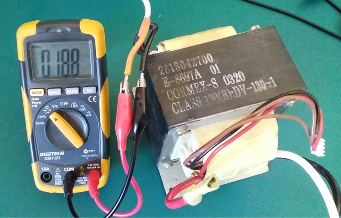
For Example, take a Transformer, the Input AC Voltage is 20 Volts, the measured DC Resistance is 18.8 Ohms:


Now we connect our input, and we measure the Current:


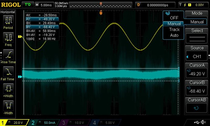
I have lots of noise in there, but the Probe is on 1x and the Scope set to 50mA on Channel 2. But, we are using no Current: < 50mA pk to pk x 0.707 = 35.35mA's

Now, mathematically, Ohms Law, Current I = Voltage V / Resistance R, so 20 / 18.8 = Current of 1.06 Amperes. We don't get this, we get less than 35.35mA's, that's a difference of: 1.06 / 0.03535 = 29.98 times.

At 20 Volts, and a Current of 35.35mA's, we have a total Impedance of: 565.77086 Ohms.

So where did: 565.77086 - 18.8 =  546.97086 Ohms come from? This is the AC Resistance.

Impedance Z = 18.8+j546.97086. This means, the Impedance ( Z ) has two components, DC+jAC, +j is the Imaginary number and can be -j in some situations.

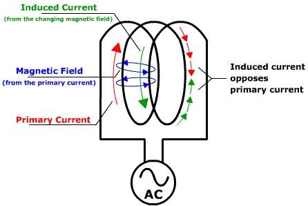
The Input Coil creates its own Resistance, due to Self-Inductance between the Turns, this Inductance, and the Change of Current, between the Turns, creates a Voltage in reverse to the Input Voltage. In other words, Back-EMF:


All this we know, from other threads, including The Reduced Impedance Effect.

In laying out Impedance, we must realise this is not Impedance Matching!


Impedance Matching

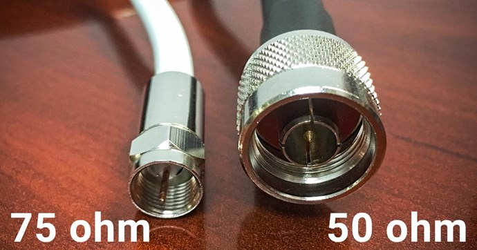
Radios, lets use a CB Radio, has a Matched Antenna Impedance with the CD Radio Output Impedance, the CB Radio has an Output Impedance the the Antenna must match this Impedance. Lets say 50 Ohms or 75 Ohms:


Or, lets look at an Audio Amp and Speaker:
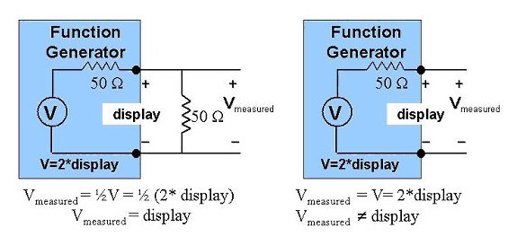
Ref: circuitdigest.com

Please Note: I don't agree with the labeling, 1V 4A 8 Turns vs 4V 1A 2 Turns?


If you are an RF Design Engineer or anyone who has worked with Wireless Radios, the term “Impedance Matching” should have struck you more than once. The term is crucial because it directly affects the transmission power and thus the range of our Radio modules.

Ref: circuitdigest.com


So, the Input Impedance must Match the Output Impedance. Impedance Z = V / I, again this is Ohms Law.

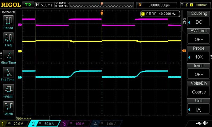
In our Transformer example above, if I short the Output, then the Impedance changes. The Input will go up:


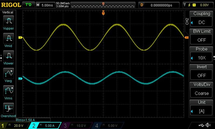
Now we have a very different input Current!  The RMS Current read: 1.58 Amperes on the Input

NOTE: 1.58 Amperes on the Input is higher than the 1.05 Amperes predicted by Ohms Law using the DC Resistance 18.8 Ohms! It gives us: 12.66 Ohms!

Now, in our example, we see very clearly that the Impedance changes depending on the load. If our Input, the Amplifier supplying the 20 Volts to the Transformer was only good for 1 Amp maximum and not the 1.58 Amperes, then we would be over driving the Amplifier. The Amplifier would heat up and fail.

A short Circuit on the Output represents Maximum Load, and Minimum Impedance, or Zero Ohms. If I placed a 1 Ohm Resistor on the Output, then the Input Current would drop down. Similarly, if I placed a 10 Ohm Resistor on the Input Current would drop even further.

This Resistance changes the Current Flow due to Ohms Law, V / R = I.

So, to make sure our Amplifier survives, and we don't blow it up, we must match the Output to the Input. This is called Impedance Matching, its how I understand it at least.

So, if the Amplifier could only supply 20 Volts at 1 Ampere, that's an Output Impedance of: 20 Ohms.

Out Load Impedance must not draw more than that. With our output Short Circuited, we Draw 20 Volts x 1.58 Amperes = 12.66 Ohms as pointed out above, not a matched Impedance.

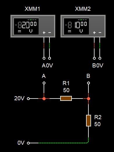
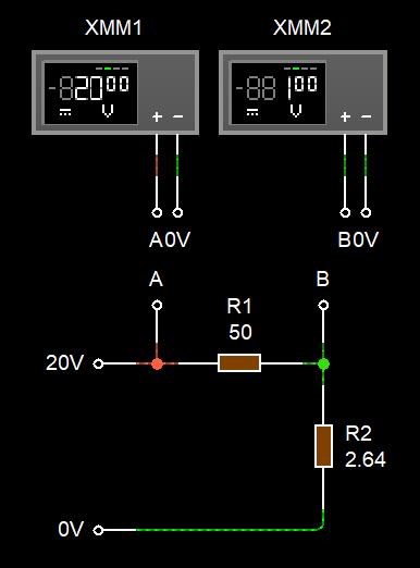
I should point out, The Output Voltage changes depending on Load Impedance:
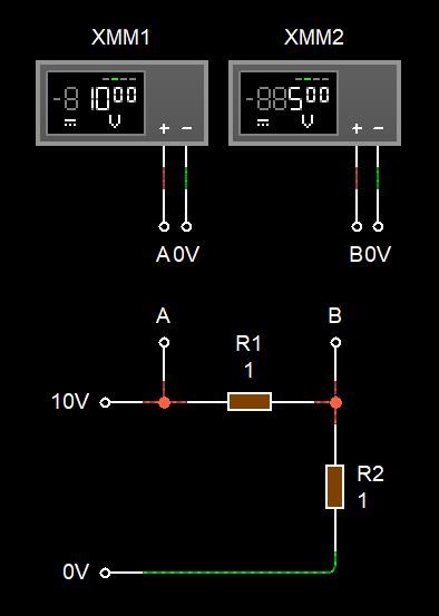
 

Where:

  • R1 represents the Input Impedance.
  • R2 Represents the Output Impedance.


There is more to the whole thing than just this example. So I have perhaps over simplified Impedance Matching some what. I hope, non the less, that this helps!

Please Note: In the above example, I show the DC Impedance, not the AC as was pointed out above. The total Impedance is AC and DC, remember DC+jAC = Z, not just DC, so my example is not entirely correct and functional in its total Mathematics. Thanks Jagau for pointing this out. You are right, its not entirely clear. wink

Please correct any mistakes and post your contributions and advancements.

Best wishes, stay safe and well My Friends,

   Chris

Order By: Standard | Newest | Votes
Jagau posted this 01 August 2020

Hi Chris
In my case what I mean is that there is not just with the output or the load that I am working on.

What I mean is that:
as an example, at the output of your signal generator which in general nowadays is 50 ohms of output impedance and one can now vary them at will according to the needs, previously the SG had a single output of 600 ohms of impedance.
As I use this old S.G. I have to install a buffer between the S.G. and the circuit to be supplied, we are not talking about charging yet. This can be done with an op amp or by BJT like emitter follower, no matter what they have the same purpose. We could have them for voltage and for current. 

This buffer will perform what is called the impedance matching between two circuits. High impedance at the input and low at the output, so the source is not affected or distorted.

I would love to hear Yo on this topic.


Not easy to explain I admit it but very interesting  discussion.
Jagau

Chris posted this 01 August 2020

Hey Jagau,

Ah yes I see what you mean now. Thank You for clarifying!

Yes, so in the case of a Function generator, the Output Impedance as you stated is 50, 75 or 600 Ohms.


Now if the Output Impedance is not right, the Voltage changes across ( XMM2 ) the Output Impedance ( R2 ):


One Volt is not enough to work with in most situations. The Function Generator is not capable of efficiently driving your Load. A lot of Reflections and bouncing about of Power will occur, and nothing will work properly! This, as you point out.

Yes, I understand what you mean now! wink

Best wishes, stay safe and well My Friends,

   Chris

Jagau posted this 01 August 2020

Yes exactly

Take your scope and test directly with changing Z voltage will not be the same.

I install a buffer in my circuit and it make a big difference. I have made myself same mistake.

Hope thus will help other. That why we are here

from Keysight

https://www.keysight.com/main/editorial.jspx%3Fckey%3D1948055%26id%3D1948055%26nid%3D-11143.0.00%26lc%3Djpn%26cc%3DJP?&cc=CA&lc=eng

Jagau

Chris posted this 01 August 2020

My Friends,

One of the better Impedance Matching Videos I can find:


Best wishes, stay safe and well My Friends,

   Chris

Chris posted this 01 August 2020

Hey CD,

If we use an Ohms Law Calculator like the one Here. Then yes, the Output Resistance when 50 Volts is applied across it, should be: 16.67 Ohms.

Its worth noting, most power Supplied are Rated above their Specified Ratings however and you might get 10 Ohms or so.

I have shown before what happens when one uses a power Supply when the Rating is over exhausted: Looking for the Knee of the BH Curve


In my case, My Power Supply just run out of Puff, it could not supply more Current. Other power Supplies might exhibit Warnings, or some sort of Protection.

When I replaced My Power Supply, I got this image:


A huge difference!

Best wishes, stay safe and well My Friends,

   Chris

YoElMiCrO posted this 01 August 2020

Hi all.

Excellent discussion.
I think before understanding the dynamics involved in
impedance maching, let's first analyze the behavior
static, I mean in DC.

As we talk about power coupling, I mean the reason for the load
in any circuit the maximum power dissipates, it is necessary
first know the bases that involve it.
By definition this coupling occurs when both resistances are equal,
that of the generator and the load, as we all know, but the real question is why?

The answer is simple….
Every source in real life has an internal resistance, we call it impedance
when it has components in the complex axis (i / J), but since we talk about DC
we only take its real axis value, that is, its resistance.
If we look at this image ...

We will see that it is formed by an ideal source of voltage in series with a resistance,
This resistance is what limits the maximum power that we can extract from said
ideal source.

The ideal voltage source is 12Vdc and its internal resistance is 1 Ohm for example.
If we short-circuit its output, the voltage at its terminals is 0 but the current
will be the one that Ohm's law says, E1 / Ri = 12/1 = 12A
Since power is V * I then power is 0 = 0 * 12.
If instead we leave it to open terminals, the voltage is 12 but
the current is 0 and again the power is 0 = 12 * 0.
If we apply a load equal to the internal resistance, the current will be half and
the voltage will also be half, in this way the power in the load
it is maximum given that P = V * I = 6 * 6 = 36W and only at that point is it maximum
because if we lower Rl, the current increases but the voltage decreases and vice versa.
The same happens if the source is current, only this time the internal resistance
it is parallel to the ideal current source.

I hope it serves you.
Thank you all in advance.

YoElMiCrO.

Jagau posted this 01 August 2020

I join Cd for your explanation on the behavior in static mode (DC) Well done, it's very clear.
I look forward to hearing you on the second part in dynamic mode (AC), certainly it will be very informative and interesting. This is undoubtedly one of the most interesting threads

According to me this thread will be followed on the planet

Thanks yo

Jagau

baerndorfer posted this 02 August 2020

what i can add to the discussion is, that we can gain more energy on the POC by adding capacitance in parallel to the load. if the cap is too small we can see that the brightness of the bulp is reduced. the CycleArea which represents the amount of magnetical flux can grow if capacitance is added. so this is a good and easy way for me to find the right point based on the load i like to use.

regards from austria

baerndorfer posted this 03 August 2020

thats right! i like to use Wima MKP-X1 capacitors. they work in mostly every condition.

Vidura posted this 04 August 2020

A very good discussion, and we'll explained the DC example by Yo. In the case of AC with the complex axis we have to deal with the capacitive and inductive components, which make the impedance frequency dependent. In the case of a load the impedance of the capacitive component will diminish with increasing frequency. In contrast to the inductive component, which will show an increasing impedance with rising frequency. This is why the technical specifications of HF devices will generally give an impedance value for a specific frequency. This value thus will be different in another frequency (range) than the specified for a given device. Then there are the special cases of resonant circuits, where eventually the capacitive and the inductive components become equal, of opposite signed, and cancel each other, leaving on only the real axis of ohmic resistance. Regarding an AC source with complex components I have to learn more about, how the interaction with the load is exactly, and will wait for an explanation of the more experienced members. Regards Vidura.

Atti posted this 08 August 2020

If you care about someone.

YoElMiCrO posted this 09 August 2020

Hi all.

Let's talk a bit about dynamic behavior ...
As Vidura says in this case the complex components appear
in the load and these depend on the frequency domain.
First, let's see its base ...
In a sinusoidal function are the RMS voltages and currents
those that are defined as invariant in time, this is 1 between
the square root of two times the voltage or current flowing through the
load, having said that let's continue ...
Again for a better understanding we will only analyze one
resistive load that has a complex component.
We use this image as an example ...

As Vidura says, the impedance remains constant only within
of a range of frequencies, but let's see why.
In the first case of the image, a series capacitor to a resistance
and this set as load.
In this case the following will happen ...
The impedance will remain constant for frequencies starting
that its two homic values ​​are equal.
Xc = 1 / (2Pi * F * C) = RL, then this frequency will be ...
F = 1 / 2Pi * RL * C), for this frequency the homic value of the capacitor
would be equal to the load resistance, if we now see its amplitude
We would see that the maximum voltage fell 1 / SQR2, or what is the same
-3dB.
Being a series capacitor to a resistance we know that the impedance
will remain constant for frequencies above the cutoff, that
to which its two values ​​are equal, it will be a high pass filter.
The same happens for a series inductor to the load, the second example ...
this time Xl = 2Pi * F * L = RL then the frequency will be ...
F = RL / 2Pi * L, the same will happen as in the previous one but for
low frequencies.
If we combine these two circuits, as in example 3,
as is logical, two cutoff frequencies will coexist, one low and one high,
it is within these two frequencies that the impedance will remain constant
and is defined as BW or bandwidth.

I don't know if it helps.

Thank you all in advance.

YoElMiCrO.

Jagau posted this 09 August 2020

Thanks Yo


It's refreshing to see the explanation that is not easy to explain and yet is so important as the '' Z '' impedance in an electronic circuit.
All the researchers here will appreciate it, thank you.


Jagau

We're Light Years Ahead!
Members Online:

No one online at the moment


What is a Scalar:

In physics, scalars are physical quantities that are unaffected by changes to a vector space basis. Scalars are often accompanied by units of measurement, as in "10 cm". Examples of scalar quantities are mass, distance, charge, volume, time, speed, and the magnitude of physical vectors in general.

You need to forget the Non-Sense that some spout with out knowing the actual Definition of the word Scalar! Some people talk absolute Bull Sh*t!

The pressure P in the formula P = pgh, pgh is a scalar that tells you the amount of this squashing force per unit area in a fluid.

A Scalar, having both direction and magnitude, can be anything! The Magnetic Field, a Charge moving, yet some Numb Nuts think it means Magic Science!

Message from God:

Hello my children. This is Yahweh, the one true Lord. You have found creation's secret. Now share it peacefully with the world.

Ref: Message from God written inside the Human Genome

God be in my head, and in my thinking.

God be in my eyes, and in my looking.

God be in my mouth, and in my speaking.

Oh, God be in my heart, and in my understanding.

Your Support:

More than anything else, your contributions to this forum are most important! We are trying to actively get all visitors involved, but we do only have a few main contributors, which are very much appreciated! If you would like to see more pages with more detailed experiments and answers, perhaps a contribution of another type maybe possible:

PayPal De-Platformed me!

They REFUSE to tell me why!

We now use Wise!

Donate
Use E-Mail: Chris at aboveunity.com

The content I am sharing is not only unique, but is changing the world as we know it! Please Support Us!

Thank You So Much!

Weeks High Earners:
The great Nikola Tesla:

Ere many generations pass, our machinery will be driven by a power obtainable at any point of the universe. This idea is not novel. Men have been led to it long ago by instinct or reason. It has been expressed in many ways, and in many places, in the history of old and new. We find it in the delightful myth of Antheus, who drives power from the earth; we find it among the subtle speculations of one of your splendid mathematicians, and in many hints and statements of thinkers of the present time. Throughout space there is energy. Is this energy static or kinetic? If static, our hopes are in vain; if kinetic - and this we know it is for certain - then it is a mere question of time when men will succeed in attaching their machinery to the very wheelwork of nature.

Experiments With Alternate Currents Of High Potential And High Frequency (February 1892).

Close