Nonlinear resonance

  • 2K Views
  • Last Post 22 December 2021
Jagau posted this 14 December 2019

This thread is the continuation of flashligh2.


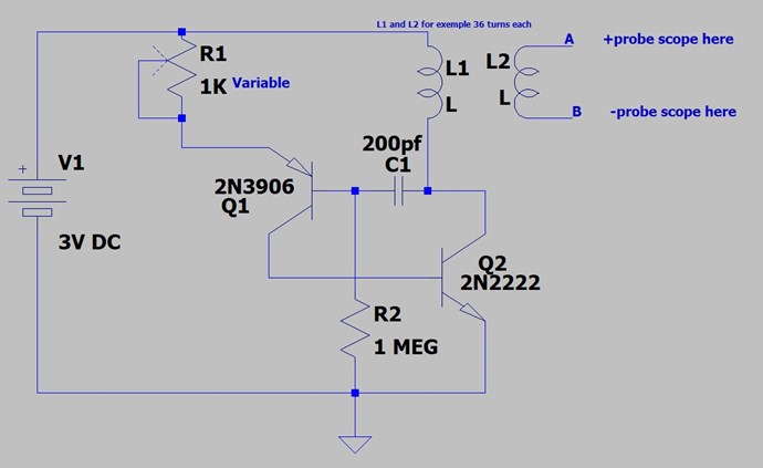
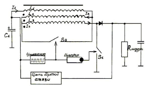
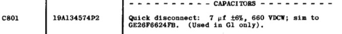
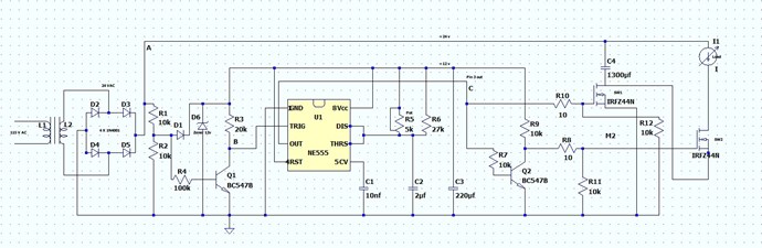
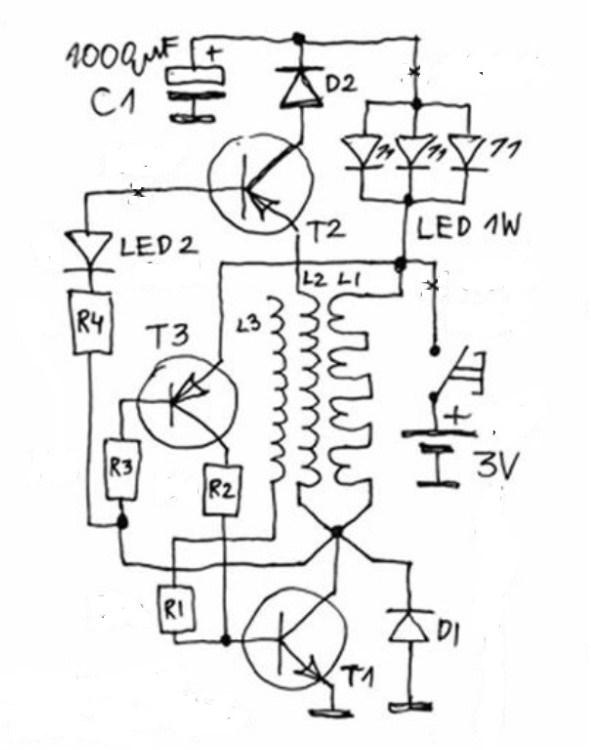
Here is the original Akula's circuit on we gonna work:

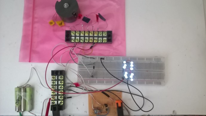
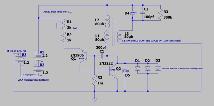
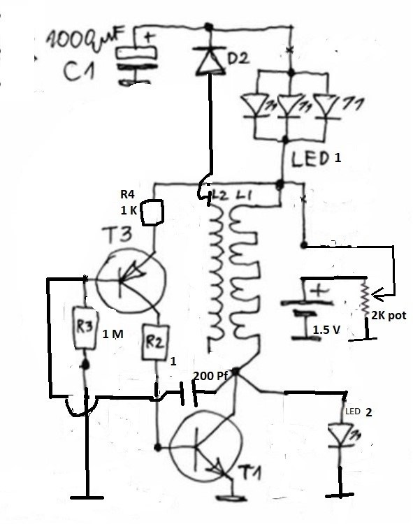
I modified the basic circuit of Akula so that it works like a high gain oscillator. It consumes almost nothing, 2 ma,.
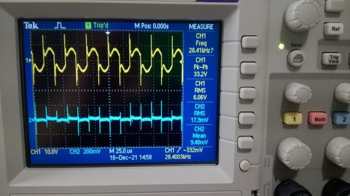
 It has the effect of a hammer (the Circuit) on a bell (the Coils) by easily adjusting the natural resonance frequency of the coils which has already been vitrified in advance with a F.G. and a 28.2 Khz oscilloscope,


I used a 2 K multi-turn potentiometer for accuracy as a voltage divider and a small 1.55 volt battery as the main power supply for the circuit.


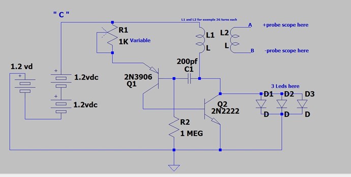
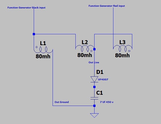
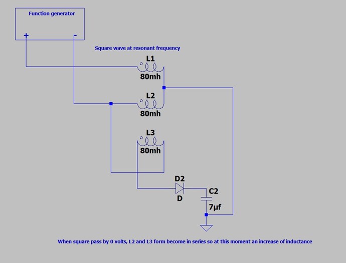
Here the modified circuit used i used in the test.
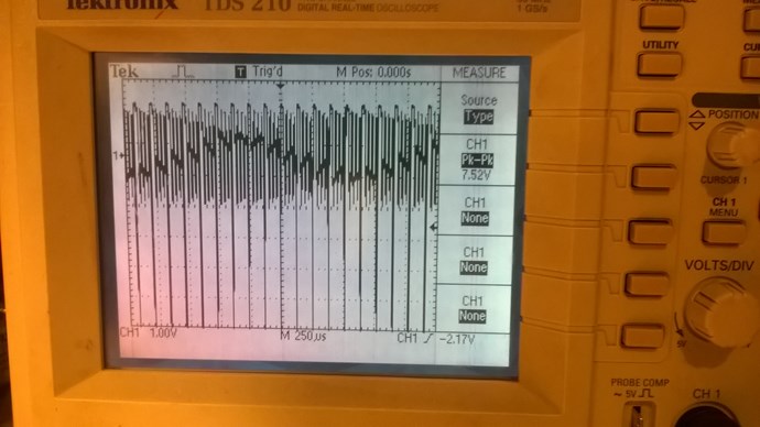
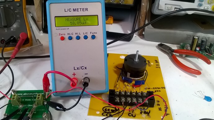
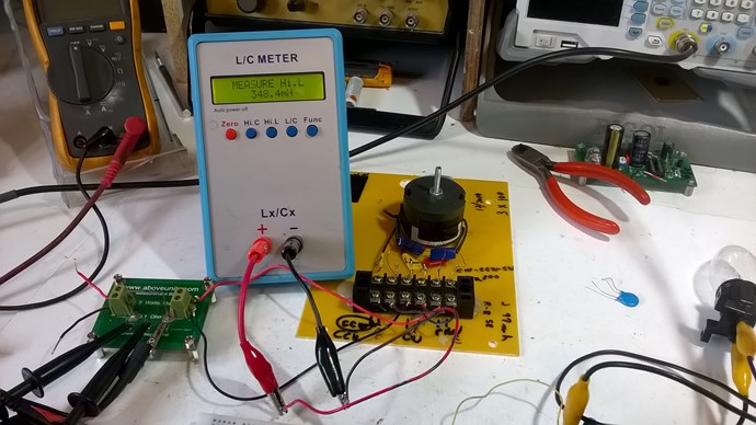
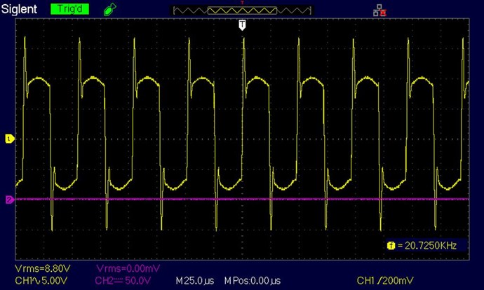
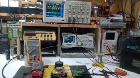
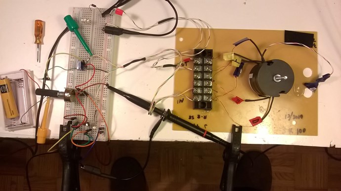
The test :


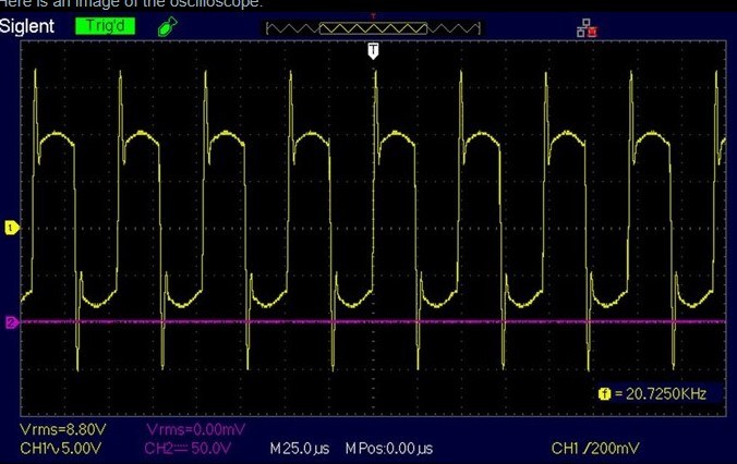
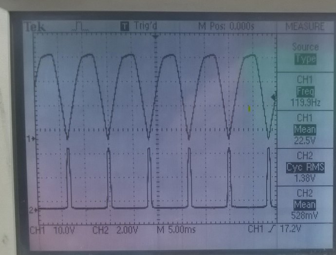
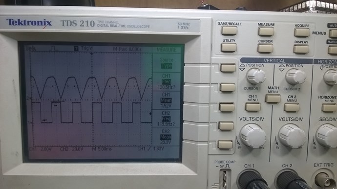
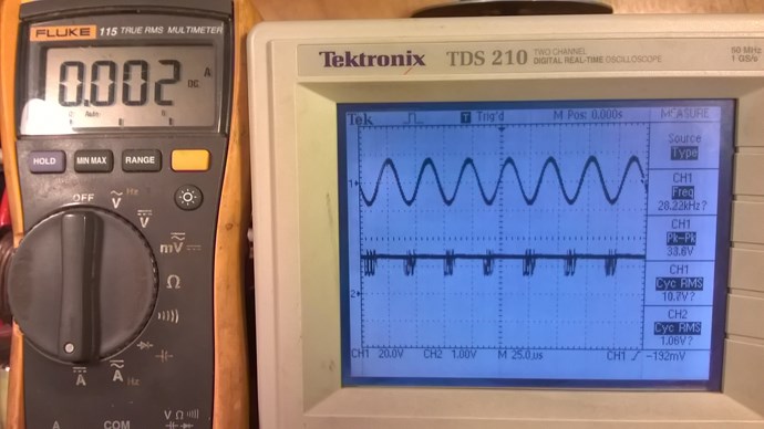
You will notice that at the natural (linear) resonance frequency of 28.22 Khz and an input voltage of 1.08 volts appearing on channel 2 and a current draw at the input of 2 ma, we still obtain a fairly good voltage approximately 33.6 volts peak to peak at the output.


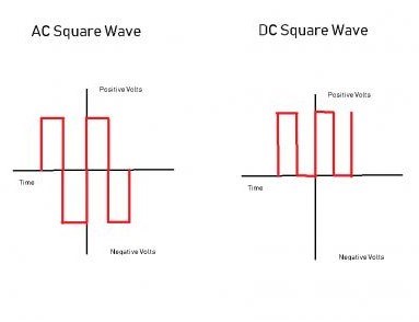
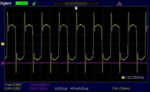
When I exceed a certain voltage of 1.45 volts ( near the max of the battery) another effect occurs quite abruptly the frequency drops to 26.77 Khz and this is what I will call nonlinear resonance.
Quite surprising this effect is the voltage X8 and so is the current.


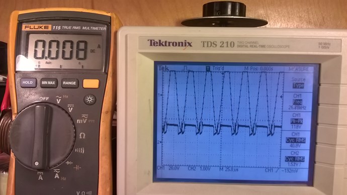
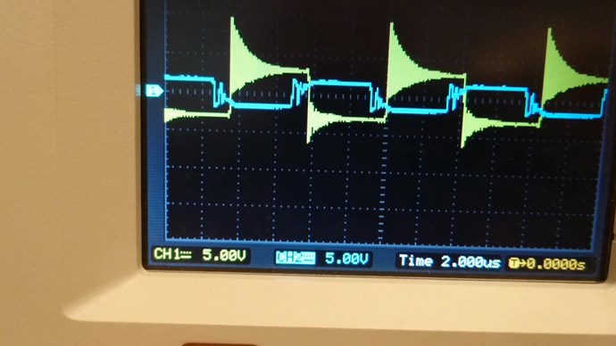
The reactive power developed by this circuit, is around 130 volts at the maximum of the battery, if we consider that the entire circuit is supplied with a single 1.5 Volt battery and there is no d external oscillator it seem good performance.

This small circuit has 2 BJT transistors 1 x NPN and 1 X PNP is the basic idea of ​​the Akula circuit. Thereafter I will modify the same circuit in order to be able to charge C1 and thus have this famous flashlight without battery.

Akula's basic circuit cannot be copied as it is built, having followed hundreds of tests of its circuit, I have not yet seen anyone succeed, but their way of thinking is very good, it you have to rebuild it while keeping the basic idea.
I believe I am on the right track.


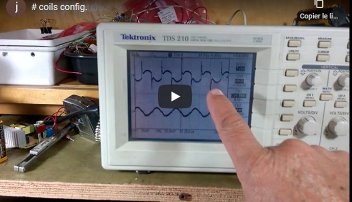
A more explicit video will follow soon, I have a little problem with my camera.


Jagau

Order By: Standard | Newest | Votes
Jagau posted this 17 December 2019

I am currently working with a 1.2 volt rechargeable battery instead of the C1 and with recharging in non-linear mode

it has been going on since yesterday with only one milliamp of total consumption and 6 LEDs on.

It’s good.

p.s. I mean linear in continuous mode so very low power and non-linear in charge mode.

Jagau

Zanzal posted this 18 December 2019

Question: Is your schematic correct in that your L2 only connected at one end?

Jagau posted this 18 December 2019

Hi Zanzal

the modify schema was to demonstrate non-linear resonance only so L2 was not plugged into one side alone.
I am trying a second schematic and it is not yet ready and that is what it gave me that the tension does not drop until very soon after 2 days.

I'm going to put it online soon and you're going to be able to try it,
Just for curiosity did you manage to achieve the nonlinear resonance effect as explained?

Jagau

Zanzal posted this 18 December 2019

Thanks Jagau. Looking forward to seeing your next schematic.

No replications for me for a few months still (at least). All my stuff is in boxes, it is hard to get access to anything and I have no space away from my little one who would take an obsessive interest in anything sitting on my desk. I've only been able to do a few very simple experiments in the last few months.

I do want to attempt a replication of what you've posted though. I think your observations and intuition are very good here and I like the path you are pursuing and intend to follow a similar one.

Jagau posted this 19 December 2019

@ Zanzal


Ok I understand your situation better now, maybe this little circuit will help you have a better time. You can also replace the 1 k resistor with a potentiometer and observe the interesting effects that will be produced.


@Atti


thank you Atti your circuit is interesting the POC produce very interesting effect, I will study your circuit,

thank you for sharing.

Jagau

Jagau posted this 14 February 2020

I had to be away recently, keeping an eye on what was happening in the forum,
Finally back in my lab.

Jagau

Jagau posted this 15 February 2020

I reread Edwin Gray's invention and it gave me a fantastic idea that I had been looking for for some time. It was a genius this guy,

SPLITTING THE POSITIVE


Besides, when we look at Akula's setup it works the same way.
Finally I found a set up which seems to work well.


I'll keep you posted.


The best way is still to experiment.


Jagau

Chris posted this 16 February 2020

HeyJagau,

We have a few threads here, work from Wistiti and L0stf0x: Split positive + Plasma generator + Bucking Coils Combination

I hope you find this useful!

Best Wishes,

   Chris


Wistiti posted this 16 February 2020

Hey Jagau. Will love to see your experiment!

Jagau posted this 16 February 2020

hi Chris

Yes it is a very interesting thread that I had already read during my research when I joined this forum, I also proposed it to those who want a conclusive experience and with results. It helps a little to understand what Edwin Gray meant.


Yes, I rediscovered this very interesting concept, but as part of the Akula LEDS lamp.


There is no battery switch between the input and the output and the batteries must always remain fully charged, that is to say in the cricuit that I am currently experiencing.


For the moment I am experimenting this kind of circuit but with only 3 small rechargeable batteries at the input and  none at the exit.
The system has been operating for more than 2 days with 6 LEDs plus the operating circuit and the batteries continue to charge. I add other LEDs to stabilize the system.

I rediscovered this concept by re-reading the invention of Edwin Gray and by re-reading the book by Peter Lindeman on how to divide the positive. Do not forget that sharing the positive also applies to capacitors as in the case of Gray

I'm going back to my laboratory.
The best way is to experiment.

Jagau posted this 17 February 2020

Good morning all
After 3 days, without interruption the small circuit does not want to fall.
I added 3 other LEDs for a total of 9 LEDs.
The 3 small AAA rechargeable batteries did not decrease by 1 millivolt in 3 days, on the contrary, they remained stable.

A first observation; taken with the oscilloscope shows that the recharging of the setup is exactly 1/4 of the resonance frequency of the main coil which is at 28khz.

Here is scope shot:

You can notice the sinus shape in the center.

A view of complete set up, circuit, potcore, led and batteries:

Did anyone try my first circuit at the start of the thread?

Other observations, photos and a circuit will follow.

P.S. John Bedini wrote on his web page: ''This has been on my pages forever, but nobody understood it.''

I wonder what he meant by that


Jagau

Jagau posted this 18 February 2020

Hi all

I would like to present you a very simple circuit to make but how useful.

It's the same one I use for what's going on in the project above.
You can use the 2 inductors of your choice as long as they are on the same core, for mine I use a potcore.


As soon as they are connected by 3vdc it starts to oscillate on its own and in addition if you look on your oscilloscope at point A and B it adjusts by itself to the resonance frequency. Very nice little circuit simple and easy to do. 

Thereafter I will be able to explain to you how I achieve what I did.

I think it was one of Akula's favorite circuits but modify by me as you can see at the beginning of this thread.

P, S, The variable resistor 1K does not change the frequency, it is there to adjust the gain of the circuit only.


Jagau


Wistiti posted this 18 February 2020

Hi Jagau. Does one of your l2 leg are not connected to anything like in your schematics on the top of this tread?

It will be nice to know a bit more on your experiment.

Thank you!

Jagau posted this 18 February 2020

Hi wistiti


Yes these are the first modifications at the beginning which had been made in the system has had an evolution. It is for this reason that I redid the basic circuit as simple as possible above, it is the same as on the little brown board on the photo above. The goal is to progress slowly but surely in the explanation of the circuit if you build the last little circuit very simple above, I could guide by the following it will be less complicated like that, I think.

@ CD 

I understand you very well CD, there are so many interesting things to do in this forum that we do not want to disturb others in our own experience, but it is part of the game. Don't worry CD, I'm also following your experiences with a lot of interest.

Other questions?

Some news:


At the fourth day the system still works as well the voltages of the 3 batteries are always higher than the nominal voltage of each which is 1.25 volts, they stand between 1.3 and 1.4 is great.


Another observation, the mornings of strong sun the ions increases a little and the evening decreases a little but never below 1.3 each.


Jagau

Jagau posted this 19 February 2020

Hi all

Now we will add 3 LEDs in parallel and 2 others battery in the circuit.
Place an ammeter at point C and adjust the 1K pot to get 3 milliamps.
I hope you have successfully completed this part because the next one is the most important.

News
Since last saturday, February 15, the system is still working well. The LEDs are on and the voltage barely fluctuates.
Jagau


Wistiti posted this 20 February 2020

Thanks Jagau for sharing! I will try to replicate when the time permits. Maybe the next weekend.

Jagau posted this 20 February 2020

Hi Wistiti, You are welcome with any questions.

Okay
I know that rechargeable nick-cad batteries have a capacity each and a nominal voltage. So it is easy to calculate the time the circuit would operate under a certain load and the voltage would drop linearly every 24 hours.

This is not what happens, the voltage varies in + or - no more than 0.001 volts and it remains stable at above the normal nominal voltage for this type of battery which is 1.2 volts, they are all the 3 at the over of this nominal voltage and sometimes reach 1.4 depending on the hours of the day.


Another beautiful puzzle to elucidate?

Jagau

Jagau posted this 20 February 2020

And now the first version of the complete circuit.


I am going there gradually so that you can understand how it works

Jagau


Jagau posted this 21 February 2020

Good morning all:


In this sixth day of experimentation I have built since yesterday a second circuit which works just as well as the first so we can replicate it.


I build this test circuit with larger batteries and the power is evident on the LEDs. The goal is to slowly increase the power to make it shine with an incandescent lamp.

Jagau

Wistiti posted this 21 February 2020

Hi Jagau. Does your replication use again a pot core? Have you try with another type of core? Ring, rod, metglass, ...

Thank you!

Jagau posted this 21 February 2020

Hi wistiti 

You understand that I would like to improve this circuit which works in very low power with a larger one, so as not to change a winning combination I have to replicate exactly the same with a potcore.
However I would like to know if another has succeeded with a different core.


Jagau

Jagau posted this 21 February 2020

Hi all

One of the advantages with this kind of auto oscillator is that it does not waste energy in order to produce a pulse.
The frequency is determined by the RC network which produces a constant time with the 200Pf capacitor and the input impedance Z of the coils to pulse.

With this capacitor we can oscillate between 20khz and 130khz, so resonant frequency is egal to  1 divide by ZC 

in other words it adjusts itself

Jagau

Jagau posted this 21 February 2020

In this project we have to consider 3 key elements.

The first is the nonlinear resonance, as demonstrated by the thread

The second is the theory of "YoElMiCrO", which speaks of the negative slope in ferro-resonance

Yo quote:
Voltage increase is related to the negative slope that has the magnetic permeability of the core

the third and very interesting one is by Edwin Gray on electrostatic transfer while sharing the positives.

This is a lot to check but should be checked, 

Jagau

YoElMiCrO posted this 25 February 2020

Hi everyone.

I could not be active in the forum due to work problems.
But whenever I can go to review all the findings they find.
This is a community like no other on the net.
I think I can continue with the experiments I left a while ago.

@Jagau.
If you don't mind, I pass a circuit with which you can see
the behavior of the back emf when it returns from the negative slope in this treat.
As Vidura says, in conventional designs it is forbidden to saturate
any ferro-magnetic core.
Now...
If we start thinking ...
It turns out that in the linear region of the hysteresis curve, during the ton cycle
B grows and permeability grows too.
but when we turn off the sw the current drops (-di / dt) but the permeability too.
However, if we make permeability pass through its negative region during
Ton cycle, when Toff touches the current will fall as before, only the permeability
It will increase now.
If the inductance grows during Toff and the current remains relatively constant, we can
Have an energy gain.

Thank you all in advance.

YoElMiCrO.

Jagau posted this 25 February 2020

Hi Yo

You are always welcome for your comments Yo.
As you can see in my first experience at the start of the thread, I noticed this effect you are talking about,

when the inductance grows the frequency decreases, is that what you mean?

Jagau

YoElMiCrO posted this 25 February 2020

Hi everyone.

@Jagau.


Yes, that's what happens.
It turns out that Ton's time is compressed, because the current that is
reflect of the load is the component that defines the static path in the circuit.
For stable operation, this current must remain constant throughout
at this time, it should be noted that the turn ratio should be calculated using
Biot-Sabart's law and not Faraday's.
On the other hand, during the Toff cycle said primary peak current should
fall to 0, in turn the magnetic permeability of said core (ur) when returning from the
negative slope until the value you have for Br will increase the primary inductance.
In this way the time of Toff expands, being a non-linear process and not fulfilled
volt-second equations (VpTon) = (VfbToff).

In the shortest possible time I climb the circuit, thank you.

YoElMiCrO.

Jagau posted this 25 February 2020

Hi Yo

Completely agree with you the law of BIO-Savart is that which we must use in the cases of non linearity and in time variation, the law of faradays is for the very linear systems in closed loop.

Your future circuit to come look very interesting.
Thank you for your comments.
Jagau

YoElMiCrO posted this 27 February 2020

Hi everyone.

Yes, we all know that the rise / fall time is controlled by the current
of the gate, forget about the 500 Ohm resistor, just to adjust that time.
You adjust it after having Ton and frequency, looking for the least noise in the way
of drain wave.
It occurs to me that we can use the miller capacity of the mosfet, I'll try!

Thanks in advance.
YoElMiCrO.

Chris posted this 28 February 2020

@Jagau,

Noticing the topic is the same but it appears the thread you created has gone off path.

Do you want me to move posts to a new thread? Or are you happy to have all this here? Happy to do what ever you wish?

Best wishes,

   Chris

Jagau posted this 29 February 2020

yes indeed there has been a positive development
in the sense that the subject of nonlinear resonance is always active
but I have no objection to bring this to the community,

I asked myself the same question,

to move it in part if it can benefit a larger number no problem, I just didn't want to distract the other threads ?

Jagau

Chris posted this 29 February 2020

Hey Jagau,

If your'e happy to keep the posts here? Or I can put them into a new thread?

I wait your advice. Of course realising Vidura and YoElMiCrO may not want to share their work.

   Chris

Jagau posted this 29 February 2020

hi vidura

Can you ask to Yo,you know it better than me,  if it does not bother to transfer the thread to the community, tell him that they feel very free with his desire, and on your side is it ok for you?
We would call the new non-linear resonance for all thread
Jagau

Jagau posted this 01 March 2020

About the leds project.

After almost 2 weeks, the batteries in series have started to drop slowly except that in reverse which is still held at 1.4 v
I learned a lot with this very simple little circuit and I plan to develop one with more power.


Jagau

Jagau posted this 22 March 2020

Small update


On the circuit that I sent you,

the more I increase the load at the output by increasing as an example the capacity of capacitor

the more consumption at the input decreases and the output voltage increases with no change in frequency,

very interesting observation, under study


Jagau

Jagau posted this 24 March 2020

Hi all

As you can imagine, it is not only us who seek to understand the mystery of the small lamp of Akula.
I recently found a very interesting article from an Indian engineering college which offers a topoly buck boost converter as Yo's proposal. They title their articles:


Self Powered Buck-Boost Converter for Low-Voltage Energy Applications.


I put it in paste.


Jagau

Attached Files

Jagau posted this 02 May 2020

Hi my friends

I am preparing an update for my trhread
I haven't forgotten you, see you soon
Jagau

Jagau posted this 19 May 2020

update


Hy my friends


By carefully studying the very well-known schematic of A. Melnichenko;


We can easily see what Chris has shown us lately. In a complete cycle we can divide it into 4 equal parts of 90 degrees.


I redid this schematic so that it works in the project of the small led lamp, because this small lamp uses the basic principle of the operation of this schematic.


We must have 3 coils, a diode and a capacitor, I will show you in a short video all the power to develop by this arrangement of 3 coils of which 2 transmit the starting impulse and I cancel the one of the middle by disconnecting it in a natural way and by reconnecting it in series and only by capturing the way in which the coils interact with each other, as Akula said, you must capture the functioning of your coils first.


No need for a complicated switch, just think about it. When I transmit the pulse (phase 1 and 3) I am in very low inductance about 45 microhenries, therefore in energy saving, when I receive at the output the inductance goes from 45 microhenries to 350 millihenries, which gives me a great increase in power.


The schematic is the basic idea of ​​the operating principle but if you plug it in as it is present, it does not work as I had already demonstrated in another post by shorting a single inductance we can not have an inductance increase in that this during the relaxation (disconnection) of the circuit in phase 2 and phase 4 of a cycle as demonstrated by Chris and CD in another post.


I am preparing this short video to show you my latest advancements in this project.


Jagau

Jagau posted this 19 May 2020

So this simple confuguration gives me at the input inductance is 58.85 uh

and at the output inductance is 348.4mh

The setup


It is ja way in which I connect the 3 coils which give me this advantage. As the inductance increases considerably you can see in the video the effect produced.
As you will notice in the setup, it is imperative to have a square wave AC, ie it goes through zero and increases in negative with the same amplitude as in positive.

Function generator who act like S1 in melnichenko schematic and no need of S2 switch,

And more at 21 Khz a functiongenerator have an outputt power contrill by the amplitude of about 45 milli watt and it is normal. I apply this 45 mw to this set up


Here the difference between a square wave AC and DC.

The effect is completely different when I use AC,

so AC square wave is better.

The video is almost finished, I'll get back to you with that


jagau


Jagau posted this 21 May 2020

Hi my friends

Here is the video:


Scope show across  0.1 ohm board current of 19 ma and voltage 5 volts, 95 mill watts or 0.095 watt at 19 khz AC square wave at resonant frequency and we get 550 volts RMS in 2-3 sec.

 At output i discharge an incandescent lamp of 10 watts 120 volts in, note the very fast increase in voltage with so low input power. I will surely lit some leds in my project of lamp with this coils configuration.

I would never have thought of one day lighting an incandescent lamp with the very low power of a function generator.

Asymetric transformer plus resonance is the perfect combination to get above unity.

Next goal, would like this leds lamp a  project succeeds.

Chris posted this 21 May 2020

Hey Jagau,

Very nice! Thanks for sharing!

We know, Charge: Q = C ⋅ V and we can calculate the work: W = 1/2 C ⋅ V2 so a quick calculation shows you have: 0.875000 Joules across the cap when its at 500V. This is all for 0.095 Watt Seconds, or Joules.

Best wishes, stay safe and well,

   Chris

Jagau posted this 21 May 2020

hi Chris
  The system has a recharge time of 2 to 3 to make an average with 2.5 we have e = (cv square / 2) = 1.059 watt /2.5 second=   0.4235 watt second  and and with the amplitude of the F.G. completely closed, I still have 47 volts RMS, 

The 10 watt 120 volt lamp is only to demonstrate the rapid increase in charge mode.
The LEDs take almost nothing. I will demonstrate later.
Jagau

Jagau posted this 21 May 2020

Hi chris


At the input I only consume P=E I  5v x 19 ma = 0.095 watt
and at the output I have 7Uf x 550v squared /2 and divide by 2.5 sec average = 0.4235 watt per second

do we arrive at the same result,  don't worry i can be wrong, tell me what you think your idea is important to me?

Jagau

Chris posted this 21 May 2020

Hi Jagau,

I trust your math, I believe you are right. Yes I believe we get the same result at the end.

Best wishes, stay safe and well,

   Chris

Jagau posted this 21 May 2020

Thanks Chris I appreciate your answer.


I’m learning myself too like all of us, that’s why we’re here.
If others find something I will appreciate your help
thank you


Jagau

Chris posted this 21 May 2020

Hey Jagau,


double Uf = 7.0;
double F = Math.Pow(10, -6) * Uf;
double Q = F * 550;
double W = 0.5 * F * Math.Pow(550, 2);

Q = 0.00385
W = 1.05875


A quick method:

  • ‭0.095 x 2.5 = 0.2375‬ Watts over 2.5 seconds or 0.2375 Joules Total Input.
  • 1.05875 Joules = 2.5 seconds, to get 550V in a 7Uf Cap = 1.05875 Joules Output.


COP = 1.05875 / ‭0.2375‬ = ‭4.4579. If someone wants to correct me, please, I would be grateful to point out any mistake.

Best wishes, stay safe and well,

   Chris

YoElMiCrO posted this 21 May 2020

Hello everyone.

@Chris.

You're right, power is energy per frequency (Ef) or energy between time (E / t)
as well as voltage per DC current.
So the energy expended to produce 550V in a 7uF capacitor is ...
EIt = 5 * 0.019 * 2.5 = 0.2375 joules.
Let's calculate the energy stored in the capacitor ...
E = Vc ^ 2C / 2 = (550 ^ 2 * 7 * 10 ^ -6) / 2 = 1.05875 joules.
The energy efficiency is Eout / Ein = 1.05875 / 0.2375 = 4.4579.
Corroborating your calculations.

@Jagau.

Yes, it definitely shows AU.
In all the experiments I have done I always had the same
problem, only E appeared but nothing of I.
The only solution I found was through capacitors, these
they store charge E and have the property to use time to
produce I, since charge equals current times (Q = it).
It was for this reason that I dedicated myself to finding another way.
Bravo, good demonstration, we must analyze how it can be done
so that it is 100% functional in closed loop.

Note:
If you look closely at the input waveform, you will see that your system
it is ferro-resonant, it is necessary to obtain loads and it is
with what Nikola Tesla discovered in his time in another way.

YoElMiCrO.

Jagau posted this 21 May 2020

H iChris and Yo

I had a lot of trouble sleeping last night.
I redid the calculations several times in my head
I am very happy to see that you both confirm AU

I am very happy to have realized this in the site here Aboveunity.com

Aboveunity.com is the future


Thank you


Jagau

Jagau posted this 22 May 2020

Hi all

For those who would be interested in building, something you should know when making your 3 coils, they must be wrapped one on top of the other with a gap made of electrical tape (air space) between each coil

. In fact it is as described in the patent of Andrey Melnichenko:


  This is obtained by the presence of a weakly magnetic air or space, resulting in a magnetic field energy greater than the work of the current source to be magnetized and which can be converted into electricity during demagnetization.


In addition, the 3 coils must have the same number of turns which ensures the same inductance. By doing this the second and third coils will be a few turns longer, as Don Smith mentioned, a few turns longer on a two-sided side compare to first one.

Jagau

YoElMiCrO posted this 22 May 2020

Hi Jagau.

I'll try as soon as I have the shortest time.
Thanks for sharing the data.
I have a question, what are the characteristics of the capacitor
that you have connected, it looks like oil.

Thank you in advance.

YoElMiCrO.

Jagau posted this 22 May 2020

Hello yo
For the condenser not sure if it is with oil it is what General Electric used in the power supply of high power. It is a Delektrol number 19A13457P2
I believe that the specs can be found on the internet.
For spec: 7 Uf-660vac GE trade mark.
I have 2 of these capacitor, it was used in power supply CVT in conjunction with a special Xfo built in the 1960s, maybe the floyd sweet team worked on this plan, being himself an ex employee of GE in usa. 

I send you a schematic, they even used ferromagnetic transformer technology at that time.

I joint you a description form the book of this P.S.

P.S. I will redraw my schematic, he is difficult to follow,I will do it again for a better understanding

Have a nice day

Jagau

YoElMiCrO posted this 23 May 2020

Hi Jagau.

Thanks again for the info.
I tell you that I have searched the net for the capacitor unsuccessfully.
Yesterday I did a quick experiment with your next analysis.
I have to say that you found the method at least current
ideal for storing this electric field that has no current,
but due to the capacity of capacitors to integrate current
we can have real energy from them while storing electrostatic charges.
This is due to the type of capacitor in question, I am still looking for its characteristics.
If I am right, changing the type of capacitor you would see that it stops working,
Well, my experiment did not work, having all the parameters the same.
Today I will try to find the ideal capacitor to be able to replicate your system.
You can change the configuration according to my analysis, because I think I know
what is its operating principle.

After doing more experiments I will tell you my results.

Thanks again.

YoElMiCrO.

Jagau posted this 23 May 2020

Hello Yo


A photo of the condenser part number.


DIELEKTROL no pcb, the fact that they write no pcb probably means in oil but without pcb.

 You probably know IEEE
They published an article on dielektrol II a long time ago


here is the link on the article

https://ieeexplore.ieee.org/document/4080869

For my part I will repeat the test with different capacitor to check if I have a difference in the effect


Jagau


Vidura posted this 23 May 2020

Hey Jagau

Excellent experiment, very simple and conclusive. The capacitor is almost certainly oil filled, the Russian investigator Sergei Deyna also mentioned some experiments with predominantly longitudinal oscillations to result much better with this oil filled capacitors.

Today I had a couple of hours free and tried to make a similar setup as yours, using a small EE30 ferrite with tree coils 35T each. As I didn't have a capacitor of this type, I used a 330uF 400V electrolytic for collection. I could dot get the ferro resonant oscillation, likely too poor self capacitance of my coil, so I added a 100nF cap in series with the entrance and then could see the effect. In a narrow frequency range I could bring the cap up to nearly 70V with 8Vpp fed with a half bridge. I didn't make measurements and math's for the moment, will go on playing with this to see how to increase the effect. I tried with a gapped core for comparison, but the efficiency seems to be better with out gap.

Thank's for sharing.

Vidura.


Jagau posted this 24 May 2020

Hello Vidura

Excellent, I'm glad it worked for you too.
If you have microwave oven condensers, this works very well with this type as well.
thanks for the feedback, keep me posted
I am making a small list of capacitors with which it works
Jagau

Jagau posted this 26 May 2020

Hello

After having made different test on different type of capacitor
the oil capacitors are very efficient and the chemical capacitors with a low ESR are also very good.


I redid my coils with a higher inductance and I now reach 642 volts DC on output capacitor 7 uf 660vac

Jagau

Jagau posted this 27 May 2020

Hi all

Another important detail about building

The Rx coil,  the one that receives the energy,it is the first to be rolled up,

it must be followed first by the 2 bifiliary windings, 
If you do it backwards it will only work at half the power. I will explain in another post why this happens.


Another thing, the gap must be between the coils and not between the ferromagnetic material as some have interpreted, very important. For those who have already experienced this phenomenon  2 coils effect it's like two plates of  a capacitor, I think Akula had guessed it, think about it when you build the gap.


Jagau

Jagau posted this 01 June 2020

Hi all


Even if I am not often present in the forum these times do not worry, I experiment a lot with all kinds of different parameters, will come back with other very encouraging results


Jagau

Jagau posted this 22 June 2020

Hi all

As Ruslan says in his video, an important point is when you meet this figure.

I did it with the beat of 2 frequencies

photo to come, And explain it to you in detail

jagau


Jagau posted this 31 July 2020

My friends

 
The last few days I've been working on this thread's project a lot. I have tried several ways to virify the last results and I always arrive between 2.9 and 3.2 of A.U.No matter how I go about it, I always get more or less the same results.


So when I will have succeeded in controlling the input impedances (Z) in relation to the circuits involved, I calculate a result much greater than that achieved. It may be a dream but a goal to achieve.


Firstly, as Don Smith said


 The people who have successfully duplicated my experiments are those who have successfully matched the various impedance of the circuits involved.


I'm working on it now and it's a noble goal. This project is in serious development.


Jagau

Chris posted this 31 July 2020

Hey Jagau,

I am so pleased you are having good success! 2.9 to 3.2 times the Input is very good!

I have trouble understanding the Input to Output Impedance Matching. I know its common in Antenna Theory, but I still have trouble properly understanding.

I wonder, the Circuit you posted above, is this the same as your current Experiments? Of course, there is a bit of difference with circuits on this thread, and others may find an updated circuit helpful?

Thank You for sharing! Stay safe and well My Friend,

   Chris

Jagau posted this 31 July 2020

HI Chris

Yes it's a very good idea and I will put the circuit in place with an
Up to date, 

Regarding impedance adaptation, you will find the context in this article of what DonSmith is talking.

https://en.wikipedia.org/wiki/Impedance_matching

I mean adapting one circuit to another for maximum energy transfer and without distortion of the source circuit.

In my circuit it makes all the difference, will show result later.

Jagau

Chris posted this 31 July 2020

Hey Jagau,

Thanks, I understand Impedance, and in Antenna Theory Impedance Matching, but in our machines, I find it hard to understand for some reason.

The reason we need to find a Load that needs to match the Machine we are working on is the Impedance Matching, but I need to find why this is the case, what restricts us in this area. Maybe the Core itself?

I should start a new thread on this Impedance Matching topic.

Thank You for sharing! Stay safe and well My Friend,

   Chris

Jagau posted this 01 August 2020

yes exactly i think having a new thread on the subject will be really an important point for our research that all of us do.


The game of impedances is very important not only in the antennas but also between the different circuits that we use.
As an example a microphone, a guitar or an op amp between two circuits, connected in buffer mode which has a very high input impedance compared to the output having a very low Z,  to name only those.

The energy transfer is better when the impedances are adapted and this does not distort the source.


Jagau

YoElMiCrO posted this 01 August 2020

Hi all.

@Jagau.

Yes, your circuit is 80% dependent on impedance maching
between both Generator / Load and 20% ferro-resonance.
I tell you that I managed to replicate it 100%, but only after
to properly couple the two.
Here is an image of the oscilloscope.

As I commented earlier, the leakage inductance is the
causing to open that window to the sea of energy and the capacitor
to store it for later use.
Your two inductors coupled in non-inductive mode to be
biased cause leakage inductance to grow and polarize
the external environment to them, is that gap between them of which you speak.
If the current flowing through both is such that Ur is maximum
then the collector coil is capable of capturing said energy.

Thank you all in advance.

YoElMiCrO.

Jagau posted this 01 August 2020

 Hello yo


I see that we are on the same way of thinking,

as much in the impedance adaptation as with the gap which is very subtle but very important.

The source deformation is minimal and in addition a surprise addition in the peaks voltage.


Well done we are all on the right track and it will be very beneficial for everyone in this forum.
thank you for sharing my friend


jagau

Jagau posted this 02 August 2020

Hi all

A circuit update more easy to read, 100 turns each and follow the dot.

The one i am working now. Do not forget the gap between the coils, this circuit is very simple but requires attention to the assembly and like the CD said, 

it is necessary to understand the scene that the coils and how they work between them in order to connect them well,

Another update will follow with an emitter follower and an ideal op amp (TL084) in order to adapt the impedances well.

Jagau


Jagau posted this 07 August 2020

update

In the same setup, when I add a fourth coil and a second 7 uf capacitor I get 350 volts in each capacitor so 700 volts total and this without increasing the load at the input.


So a non-inductive coil does not affect the input only the magetic part is transmitted.
I think that's what Don Smith meant by only dealing with the magnetic side and not the electric side.
In study
Jagau

Chris posted this 07 August 2020

Hey Jagau,

I 100% Agree:


Thanks for the Update!

Best wishes, stay safe and well My Friend,

   Chris

Jagau posted this 07 August 2020

Thank you for your help Chris you just confirmed me and gave me a great idea at the moment.

over onto the counter part of the magnetic side none of those laws apply and it's a whole different system and most of the critical information they're missing intentionally so what in effect what you have on the magnetic side you can make as many copies of it as you want without depleting the source 

I am going to try something to finally prove to me that a non-inductive coil is like a transmitter and that the receivers do not affect the input.
in experimentation, thank you
Jagau

Jagau posted this 17 October 2020

Hi Yo

Excuse me Yo I had misjudged your oscilloscope image. You have probably noticed that even if you short the output it does not affect the input at all.

Jagau

Jagau posted this 24 October 2020

Update

Hi all
The project is ahead more than I hoped, in another post I gave you a voltage of 700 volts, I now managed to get near 1 Kv, a lot more power always with the same setup at the input, so even more power.

Still have other great ideas for more powerful development. Slowly but surely.

More than unity is possible, I tell you.


jagau

YoElMiCrO posted this 24 October 2020

Hi everyone.

@Jagau.
Do you know what is the material of the Pot Core you use?
I have done many experiments in these last days,
I think I finally know what is the mechanism involved.
But still not 100% for not being in any textbook.

Thanks in advance.

YoElMiCrO.

Jagau posted this 24 October 2020

Hi yo

I bought them from Ebay some time ago.
These are GU42 core ferrites with AL 6000 is what interested me at the time.
As you know it with a high inductance factor like this one can have effects more quickly with very little winding.
The books do not tell the whole story, the proof of this in my other thread on, ferrite core at work, I had never observed such a waveform. When you reach this stage you are in another world which is even more surprising is that the oscillator does not work like a normal oscillator.


Jagau

Atti posted this 24 October 2020

Hi.


I don't know what it's about. But somewhere in my work, I’ve come across this wave shape somewhere.


Atti.


Jagau posted this 24 October 2020

 Hi Atti
A peculiarity of this waveform if we look closely gives us a good idea of the concept that I have already discussed in one of my utube video.


Take a good look to the AC square wave waveform with the cursor right in the center that separates the two polarities. In addition, what is very interesting, the small peaks at the start of each pulse exceed the average of the waveform, which indicates to us that the ferroresonance is taking place.
This is an excellent result Yo.

Atti if if you have already had this waveform you are on the right track


Jagau

Atti posted this 25 October 2020

Hi Jagau.


In addition, what is very interesting, the small peaks at the start of each pulse exceed the average of the waveform, which indicates to us that the ferroresonance is taking place.
Atti if if you have already had this waveform you are on the right track


That's exactly what I thought. I observed this peak above the signal during a measurement. I don't know exactly which layout it was anymore, but I'll find it. If I have it, I'll show you. Thanks for the reply.


Atti.

Jagau posted this 01 November 2020

Thank you for your help Chris you just confirmed me and gave me a great idea at the moment.

over onto the counter part of the magnetic side none of those laws apply and it's a whole different system and most of the critical information they're missing intentionally so what in effect what you have on the magnetic side you can make as many copies of it as you want without depleting the source 

I am going to try something to finally prove to me that a non-inductive coil is like a transmitter and that the receivers do not affect the input.
in experimentation, thank you
Jagau

Hi all
the experiences happen very quickly and successfully
as I succeeded in duplicating the magnetic side, I can easily
duplicate and even more as don smith predicted.
Am in experimentation to check this early and will keep you posted on the results soon
Jagau

Atti posted this 03 November 2020

Hi.

I have one of the resonance points. The yellow trail is the H bridge control sign. When this resonance point is there there is some recharging to the power supply.

Atti.

Jagau posted this 03 November 2020

Hi Atti


there is some recharging to the power supply.


You mean that compared to the number of amps at the input you have the same result but the current drops at the input??

Jagau

  • Liked by
  • YoElMiCrO
  • Vidura
Atti posted this 03 November 2020

Yes. See the video uploaded to the Vidura thread. History as well.

  • Liked by
  • YoElMiCrO
Jagau posted this 03 November 2020

Hi all
A video from Don Smith who declares that several components in his system do not need to be there.


Don video; Okay you want to look at it for a couple of minutes here and then we'll start talking about, it there's a number of unnecessary parts there that we're

actually put in there because people expect to see them actually on this you

can take everything back this way and take it off of there and it will work

just fine you can also take the spark gap off of it and it will still work

just fine and the reason for that is that in the coils they have their own

specific resonance due to the fact that they have both capacitance and

inductance and when you cross that on a chart you find that that particular

length of wire will have a specific frequency and it will load and unload by

itself and you don't need spark gaps or you don't need anything else your Tesla

coils.  


This is what allowed me to duplicate the voltage at will without affecting the input, as Mr Smith says and it work.

He call this D.S.E. (don smith effect)


Jagau

Jagau posted this 21 November 2020

An Answer to America's Energy Deficit - 5th Edition - January 1997.pdf

An old document from Don Smith specifying that:


The electrical circuit equivalent o a bloch wall is a diode.

Very interesting information and many others which do not appear in more recent books

Fighter posted this 01 December 2020

Hi Jagau,

I have 4 questions about your device:

  • what's the size of the gaps between the coils ? that's important. maybe 1mm ? more ? less ?
  • what's the size of the wire ? I have some 0.4mm wire available here
  • I have an AL 9500 potcore, do you think I should use a lower number of turns ? you use 80-100 turns per coil for your AL 6000 potcore
  • I don't have oil capacitors, so low ESR capacitors are working well with this ? is the effect still present when using them ?

I intend to experiment this with your AC oscillator, to replace the signal generator in the diagram.

Thanks for your advice !

Jagau posted this 01 December 2020

Hi Fighter

      1. Between the coils there is only the thickness of the black electric tape with only one turn this allows the maximum capacity between the coils.


      2. AWG is 24


      3. Mine have Al 7800 with 9800 it will be better. I use exactly 100 turns, which is important for the correct frequency. With 100 yours you will have between 26 and 29 Khz at the resonant frequency.


        4. As Tom Bearden said the more the capacitor has the internal regularity to the deformation the better it works, for LOW ESRs at these voltages there is not much difference. It also works with propylene capacitors.There are two definite advantages to using oil capacitors


        1. As I work in high voltage, it helps prevent arcing from between the two plates.


        2. Better temperature stability so that it works optimally


          You will have approximately 40 to 60 times the output voltage of what you place at the input
          Wound first 2 coils CW-CCW and last one CW
          What people don't realize is that 2 coils on top of each other is like a capacitor, you see the effect depending on the capacity of your set up, I think you must have observed this effect with your Romanian ZPM
      hope this help
      Jagau

Jagau posted this 06 December 2020

Hi all

Just a link test 

ABOUT EnerGenius Favorites 

You will be able to appreciate this document with many very interesting links

Jagau

Chris posted this 06 December 2020

My Friends,

I want to say, Jagau is right, when he states what he states. Coils in this configuration have Capacity!

What people don't realize is that 2 coils on top of each other is like a capacitor, you see the effect depending on the capacity of your set up, I think you must have observed this effect with your Romanian ZPM


I can not prove this, but I believe, this is more than Inter-winding Capacitance! I believe this is something to do with the Magnetic Field, a Capacity of Flux of sorts. In other words, the more flux the System has, the More Capacity, almost interlinked to Inductance in some strange as yet, not understood way.

@Jagau, great to see you using the new File Manager! It si so simple and easy! Once others get onto this, it will be a tool no one will want to go without! 

@All Readers, you all have a resource here, Fighter, Jagau, Vidura, CD_Sharp, and many others here, sorry for not posting a complete list of names, that have answers that are no where else on the web. I ask you, please take advantage of this. We can not be here forever.

Best Wishes,

   Chris

YoElMiCrO posted this 18 December 2020

Hello everyone.

@Jagau.

I already have the POT-Cores in hand.
I'm starting the experiments.
Buy 10, they've got 9 whole, all right.
Here's an image.

Thanks you.

YoElMiCrO.

Jagau posted this 18 December 2020

Its's look very good Yo

Good experiment and have pleasure with this.

I am experimenting at the moment about two switching mode in different time and phase angle for coils at Zero crossing Switching (ZCD). Commonly called Synchronous switching.

Almost everyone here will be able to take advantage of this as it applies to most of our switching circuits.

I will talk about all this again when my switching circuit is ready and it will not be long. I already have good results.

 have a nice day


Jagau

Fighter posted this 28 December 2020

Hi Jagau,

About your latest diagram (the one I used for building the device) I just want to make sure the points where I'm putting the output connector is correct. Can you confirm the output live and ground points are correct ?

This is how the device is looking like right now (link to larger image here):

It contains your AC oscillator and your way of building the coils in a pot-core on the same PCB, the only addition is the 2200uF/25V electrolytic capacitor on input.

There are multiple measurement pins and also sockets for easily switching the essential components: oscillator's capacitor and variable resistor, the capacitor and the fast diode connected to the coils.

The output socket is not connected yet to the circuit, just wanting your confirmation before building the connections.

Thanks for your help !

P.S.: Also, the ground connector below the 7uF capacitor, is that a physical connection ? Should I connect it on the negative output of the signal generator ?

Jagau posted this 31 December 2020

hello fighter
I could not answer your questions, I was not at home and on vacation I do not use the internet, it's an isolated place in the forest far from everything, it makes me good for my body and my mind.
I have just arrived and I will take the time to analyze your request, but at first glance you are correct in your connections, except the mass not put to the same as the function generator.
A lot of interesting message to read on the forum, I will come back to you with more precision and by the way I wish you a very happy new year 2021
Jagau

Jagau posted this 02 January 2021

Hello fighter


Your circuit board is very well done, I see that you are an experimenter in all details, thank you for showing it.
After analysis as I told you your connections are correct and for the ground it must be separated from the F.G.

With coils of 100 turns the frequency with dot on schematic you will obtained will be between 26 to 29 Khz and your voltage approximately 50 times that of the input, depending on the parameters of your potcore with 23 awg
I can't wait to hear your results

Jagau

Jagau posted this 05 January 2021

The construction of a zero crossing detection circuit goes well with the way switches (mosfet) are to be positioned in order to precisely control the 4 phases of a sine wave.
I wanted to make it a separate thread but I think it fits well here in the phase control of an asymmetric transformer.
The 4 phases of a single sine wave.

As you will notice I have built a circuit which controls these 4 states. Circuit will follow at end.

I took a small transformer to demonstrate 115 volts AC 60 cycle-
First the detection of the zero crossing

The oscilloscope allows us to see where the zero crossing occurs, and with negative cycle pass in bridge you will notice an increase to 120 hertz.

On the top waveform, see A point on schematic, that's what it looks like after passing a full diode bridge.
On the bottom form, zero crossing detection, see point C on schematic,  with the 555 on shot with adjustable DTC conduction time.

From there, the conduction time of each of these phases could be adjusted with this circuit


With a tlc555 configured in single-shot astable mode, at zero crossing the conduction time can be increased at will (duty cycle). A working cicuit with 4 cycles conduction adj.

With the 5K pot we can adjust S2 so that it opens and closes at the right time.


I think that a video is necessary in order to demonstrate the control of the different phases 1 and 3 (S1) and 2 and 4 (S2)
More info to come
Jagau

Jagau posted this 17 December 2021

My friends

new developments this are produced in order to improve aboveunity yield of this thread.


I am preparing a somewhat complicated post it may take a little time but it is coming


Jagau

Jagau posted this 18 December 2021

Hi friends

 In order to end the year on the right foot I would like to show you the again experience again a more precise way, which allowed me to go beyond unity, as a first step.
In the second I will demonstrate how to make the coils with lots of details and photos so that anyone who wants to replicate it can do it.
In the third step what I recently discovered as an improvement. It’s a lot of work to show those experiment on the web!


First stage; here a photo of the last montage with photo of the set up what the oscilloscope sees.


The calculation of the input power E in volts X  I in amps. X t sec. (E x I xT)
Which gives 6.06 volts X 0.0179 amps. X 3 sec. = input power of 0.108474 watt or 108.474 milliwatts.

17.9 ma are took on 0.1 ohm precision resistor as we can see value on oscilloscope.

As for the output power stored in the 8uf / 660v capacitor a voltage of 335volts in 3 seconds. I have done it more than 3 times with always the same results. This gives us a stored power of CV squared / 2 = 8uf X 335 squared / 2 = 0.4489 watt or 448.9 milliwatts.

Calculation of the performance factor of n = Pout / Pin = 448.9mw  / 108.474 mw = 4.1383

next will be how tomake the coils.


Jagau

Jagau posted this 21 December 2021

For the 3 coils of this project.
I have used on a 6800 inductance factor potcore and wound 100 turns for each of the 3 coils and it gives me 80mh for each of the 3 coils. Having tried different types of cores I have found that the results are pretty much all the same so other cores do, but keeping the same electronic diagram and the way of winding the coils.


The first coil L1 is clockwise 100 turns,
The second L2 coil is counterclockwise 100 turns,
The third L3 coil is clockwise 100 turns too.


It is important to isolate between L1-L2 and L2-L3 with electric tape the capacitive effect that this gives to the coils is important and by checking it with your LCR meter you will notice the minimal inductance with L2-L3 in series, it should be way below 100 uh if you got the job done well.


L2 and L3 are in opposite series (buck mode) and the third L1 is the output, it is very important to note that we are pulsing the coils L2 and L3 in order to have an output on L1 which is the first coil wound and which is closest to the center of the potcore given that this is the first coil that I wound.


I explained this before I think I was misunderstood, we are pulsing L2 CW and L3 CCW which are connected in series (buck) and the output is on L1.

schematic by PM only


Any questions?

Jagau

Fighter posted this 21 December 2021

Hi Jagau,

Thanks for the details, so COP is greater than 4 !

Did you tried to place a load in parallel to the capacitor to consume the 448.9 mW ?

I'm just wondering if the 448.9 mW can be sustained in time.

I don't know what kind of load it should be, the voltage is too high for a 500 mW LED like this, maybe there should be a voltage conversion module on the output ?

Regards,

Fighter

Jagau posted this 21 December 2021

Hi Fighter
The holidays are fast approaching and time is running out,  for your question yes I already demonstrated this in a video some time ago:


Think about it, can we light an 8W / 120v incandescent lamp with only the power generated by a function generator?

An 8 watt / 120 volts lamp that turns on every 3 seconds, due to a spark gap that switched from 335 volts, and is already aboveunity even after 1 second.
The purpose of this experiment is to demonstrate that there is abovenity, which I believe is encouraging I believe.
With the help of the members this experience could go further I think.
Example: I also tried a third coil on your ZPM and it also worked well with a little less voltage than because a higher inductance when calculating the coils in buck mode. With a potcore like you have it also works even better. The inductance calculated in buck is much lower even though the coils are 80 mh each.

I will continue to demonstrate after the holidays what other effect I have found out if there is interest in the forum.

To sum it all up: for the moment with that circuit,

i extract energy ( potentiel), but no power (wish is voltage x amperage).


Jagau

Fighter posted this 21 December 2021

Hi Jagau,

I understand, I'm not questioning the above-unity, the questions I asked were because I was thinking about a possible loop to the input to make it self-running. With COP 4 I think it is possible even with some loses appearing during the voltage conversion from the output.

I mean a part of the high voltage can be converted to amperage so we can have both voltage and some amperage available after conversion of the output.

Sorry, I know I promised to join and replicate your circuit from here, I received the components a few weeks ago but unfortunately the job didn't allowed me to work on it. It was not as I planned. It's not about the lack of interest, it's about lack of time.

I'll try to recover the gap, if not in these few days remaining until the holidays then when I return from home at the beginning of January.

Thanks,

Fighter

  • Liked by
  • Jagau
  • Chris
Jagau posted this 22 December 2021

Hi,

see what you mean ,so the in and out windings are isolated from each other, it is the principle of an isolation transformer, there can be no loop in the input and the output.


One of the cases where we can have a ground loop is when we place two measuring devices with the same common ground (earth ground) as an example a generator at the input and an oscilloscope at the output having a common mass.

In the video I plugged in the oscilloscope to show the waveforms. The same results are even after removing it and the same when I run it entirely on battery with a TL494 oscillator powered by a 12volts DC battery.


I use a battery powered DDM on the output for the voltage measurement and you will see it after the holidays the system works entirely on 12 volts battery so no ground return.

There is no power supply or battery in my circuit which provides voltage.
The Function generator has a maximum output power of 0.5watt and at this frequency 0.1 watt then the surplus come from where?

it comes from the current without mass which is converted by the capacitor into coulomb and which can be transformed back into current with mass, as Tom Bearden explains very well in his technical documents.


For the other experience you will see it is incredible to see all the energy that surrounds us.

have a nice day
Jagau

We're Light Years Ahead!
Members Online:

No one online at the moment


What is a Scalar:

In physics, scalars are physical quantities that are unaffected by changes to a vector space basis. Scalars are often accompanied by units of measurement, as in "10 cm". Examples of scalar quantities are mass, distance, charge, volume, time, speed, and the magnitude of physical vectors in general.

You need to forget the Non-Sense that some spout with out knowing the actual Definition of the word Scalar! Some people talk absolute Bull Sh*t!

The pressure P in the formula P = pgh, pgh is a scalar that tells you the amount of this squashing force per unit area in a fluid.

A Scalar, having both direction and magnitude, can be anything! The Magnetic Field, a Charge moving, yet some Numb Nuts think it means Magic Science!

Message from God:

Hello my children. This is Yahweh, the one true Lord. You have found creation's secret. Now share it peacefully with the world.

Ref: Message from God written inside the Human Genome

God be in my head, and in my thinking.

God be in my eyes, and in my looking.

God be in my mouth, and in my speaking.

Oh, God be in my heart, and in my understanding.

Your Support:

More than anything else, your contributions to this forum are most important! We are trying to actively get all visitors involved, but we do only have a few main contributors, which are very much appreciated! If you would like to see more pages with more detailed experiments and answers, perhaps a contribution of another type maybe possible:

PayPal De-Platformed me!

They REFUSE to tell me why!

We now use Wise!

Donate
Use E-Mail: Chris at aboveunity.com

The content I am sharing is not only unique, but is changing the world as we know it! Please Support Us!

Thank You So Much!

Weeks High Earners:
The great Nikola Tesla:

Ere many generations pass, our machinery will be driven by a power obtainable at any point of the universe. This idea is not novel. Men have been led to it long ago by instinct or reason. It has been expressed in many ways, and in many places, in the history of old and new. We find it in the delightful myth of Antheus, who drives power from the earth; we find it among the subtle speculations of one of your splendid mathematicians, and in many hints and statements of thinkers of the present time. Throughout space there is energy. Is this energy static or kinetic? If static, our hopes are in vain; if kinetic - and this we know it is for certain - then it is a mere question of time when men will succeed in attaching their machinery to the very wheelwork of nature.

Experiments With Alternate Currents Of High Potential And High Frequency (February 1892).

Close