Lenz's Law

  • Topic Is Sticky
  • 2.5K Views
  • Last Post 15 February 2019
  • Topic Is Solved
Chris posted this 17 July 2017

This thread is dedicated to our new Member: HD

Some excellent questions have been bought up, and they deserve a dedicated thread all of their own.

Some years ago, I studied Lenz's Law and the effects of it. Once Lenz's Law is properly understood, a lot more makes sense.


The next post is HDZeddies Post, I moved it to this thread from the Floyd Sweet Thread.

  • Liked by
  • Vasile
  • alohalaoha
Order By: Standard | Newest | Votes
HDZeddies posted this 17 July 2017

Hi Chris and all,

I have discovered your very inetersting page and have read some information. by the way I am also doing some work in this direction for a good while. 

What I want to discuss is:

I am rebuilding tom beardons device with 2 C cores of HF core material and permanent magnets in the center. As to be expected we are frontal touched by Lenz Law. in some frequencys it runs better as in others. Sometimes it seems to be very succesfull, sometimes not.

Now - to understand Lenz Law in all deepness - I want to explain my point of view: 

We imagine a simple transformer. If we are energizing the primary coil it creates a magnetic field in the core. This effects a changing in magnetic force in the core and this effects an inductance to the secondary coil. Regarding to Lorents Force and the right hand rule the magnetic force effects a at first a voltage (a potential difference of the mass of electrons) and this effects the flow of electrons according to the resistance of the connected load. During the movement of the electrons they create a magnetic field which surrounds the wire. In the coil these magnetic field are added to a big M field and this is polarised in the opposite direction as the driving M field. 

If this is right understood I have a special question to the timing of this all. 

As I think the voltage is the first we can read in the scope, because without Voltage no flow of electrons.

Then the current can be seen on the scope - electrons are moving.

Maybe in the same time M Field in the core is active.

Now the M field induces a voltage in the secondary coil ?

Then the elctrons start moving and are effecting the M field according to Lenz Law.

Is there any table what shows exactly the timing in the right way in 360 ° mode?


If you have some information or links for me, it would be very helpful.


regards HD

  • Liked by
  • Chris
Chris posted this 17 July 2017

Hi HD, Excellent questions! A lot of thought has gone into this post, lots of background!

I think you are right. However in saying this, there is more.

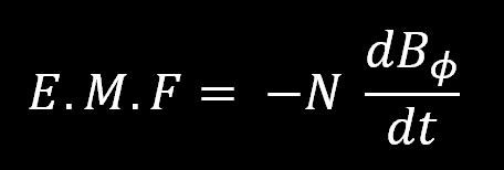
Lenz's Law is an extension to Faradays Law: E.M.F = -NdPhi/dt

where Lenz's Law is the Negative Sign (-) in the Equation.

Diakoptic's, breaking a problem down to its absolute most basic components and understanding them individually, then putting the puzzle back together again will solve more for us. Give us more answers.

What are the absolute base components?

Electrons/Ions inside the Insulated Copper Wire are the base components. The Insulated Copper Wire acting as a wave guide, a barrier, where the Electrons/Ions can not pass. Insuring only one direction of travel.

What is Voltage?

Voltage is the Potential Difference of the Charge, from one Terminal to the Other, which is the total Combined Electrons Charge on the Terminals of the Insulated Wire. If each Electron has a Charge of 1.60217662 × 10⁻¹⁹ coulombs, and there is there the Potential for 1 Ampere to Flow, then How many Electrons would we need to give us this Potential Difference in Charge?

A lot: 6.24 x 10¹⁸ electrons!

So, Voltage is the Total Charge, the Potential Difference of the Total Charge, or the Charge Difference from one Terminal to the Other Terminal.

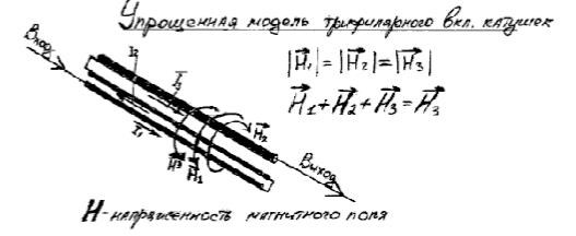
What is the Magnetic Field?

The Magnetic Field is Charge in Motion. If Charge is stationary, not moving, then no Magnetic Field Exists.

What is Lenz's Law?

Lenz's Law is a Magnetic Reluctance, a Drag, many terms describe the effects of Lenz's Law: Eddy Currents, Lamellar Currents, and others. All meaning the same thing.

Lenz's Law is Present when the Magnetic Field is present, and the Magnetic Field is present when Charge is Moving and to get Charge to Move we need a Changing Magnetic Field!

When the Magnetic Field is Changing in Time, then an E.M.F is induced, or a Potential Charge Difference can be Induced... and we surely see a very obvious pattern here!


I think it is really important to see, we have no Magic here, we are only dealing with Matter, Electrons/Ions and Magnetic Fields Changing in Time, There is nothing else! No Batteries, no Nuclear Power Plants, no Solar Cells, nothing but Insulated Copper Wire and Changing Magnetic Fields.

From this combination, we can power our Technological Worlds, we employ big expensive Hydro Power Stations to do exactly what I have laid out above!

If I think of anything else, I will add to this post. Stay tuned.

   Chris


HDZeddies posted this 18 July 2017

Hi Chris 

Thanks a lot for setting up a new topic for this theme. I have never expected this. And thanks for the dedicated answer.

I think I got the schematic of Lenz law. My initial question is, if there is a timely dependence pattern anybody has discovered. 

I mean exactly the timeline (in a transformer) between charge the primary coil with electric energy, building up the magnetic field in the primary coil, induce electric energy in the secondary coil, flow of electrons (amperage) in the secondary coil and building up the reactive magnetic field in the secondary. 

The background for this question is, that I made an observation in one of my tests, that in some frequencies the connecting of a load to the secondary coil effected a decrease of the consumption of the primary coil. 

The same phenomene is observed by other guys in other devices. Normally it would be explained with - on the way to overunity - but I want to find out, if this is effected by lenz law. 

If my observtion is in touch with a timeline on the whole schematic of a transformer it can maybe assist the changing of magnetic field in AC mode. 

best regards

HD

  • Liked by
  • Chris
HDZeddies posted this 18 July 2017

I have searched a little bit on the page and found on teaching film about antennas. In this film they explained, that the voltage and the current ind 90° out of phase. 

This would mean in sight of the transformer:

1° to 180 ° Voltage primary coil

181° to 360 ° Voltage primary opposite direction

90 to 270° current and magnetic field (B and E Field) primary coil

271 to 45° B and E Field in opposite direction

And now we are looking to the secondary coil

90 to 270° B Field arrived in secondary coil and inductance started,

This means : Electrons are pushed more in one direction and a Voltage will be created. Then electrons are flowing according to the connected resistive load. 

Is there also a delay? Maybe the voltage must be created to start moving of electrons, Then we could have also a delay of 90°. 

Or the B field pushes directly the electrons and the flow started without delay. Then the Voltage is not so high, because some of the electrons are already on the other side and the potential difference is smaller.

I am not sure exactly with this. Maybe it is a totally other timing.

HD

  • Liked by
  • Chris
HDZeddies posted this 18 July 2017

And maybe it is a difference in resonant mode or in normal mode, Sometimes I reached a resonnace frequency in secondary coil while the phenomen happened. 

alohalaoha posted this 18 July 2017

  • Liked by
  • Chris
Chris posted this 18 July 2017

Hi Guys - Awesome! Solid productive Thread!

There is an effect called "Delayed Lenz" where the propagation of the Magnetic Field can be Slower, or Faster than the Source Magnetic Field Inducing the E.M.F.

I first read about this in the book: Spin Wave Technology by George J Bugh

I believe JLN Labs has done some work on this also:


In my personal opinion, this is a path of investigation, but I would look at a more straight forward way. Why do I say this, because the "Generation" of Electrical Energy was meant fo this! We have always built Symmetrical Systems, when infact we were supposed to build Asymmetrical Systems. We don't really want to Delay Lenz's Law, we need an exact 180 Degree, or Fields exactly opposing for the "Generation" of Electrical Energy!

@Alohalaoha - The Copper Pipe with the Magnet slowly travelling the length of it because of Eddy Currents is an excellent Experiment! To fully understand this can be very beneficial!

  • The Pipe can be thought of as a single very large Turn, Shorted, or with a Zero Load Resistance.
  • The Changing Magnetic Field Induces Eddy Currents, an E.M.F and the Zero Resistance ensures Maximum Current, Maximum Eddy Currents, Maximum Lenz Law.
  • We see losses, the Magnet does have a Downward Travel, showing us that the Eddy Currents dissipate.

Lenz's Law is a critical component in the "Generation" of Electrical Energy! Once understood, it is much easier to think about its Nature and the possibilities of using it to make our Systems run by themselves!

  • Lenz's Law is ENTIRELY Magnetic in Nature!
  • If no Current is Flowing, then there is no Magnetic Field! No Lenz's Law!
  • It is a Inverse Square Law Force! It is equal and Opposite!
  • It is a Changing Magnetic Field in Time!
  • Newtons Laws of Force Apply, but we must use the Asymmetric Version: Action, Reaction and Counter Reaction!

Mathamatically, we can see, if we have three forces, all of magnitude x = 1, and we arrange the Vector, having Magnitude and Direction, products so: --> + --> + <-- = -->

    1 + 1 + -1 = 1


This we have seen before! Andrey Melnichenko


I should also note, Phase Shift in a Coil or a piece of wire is entirely due to the Inductance in the Coil. If a Coil looses all of its Inductance, then there can be no Phase Shift. The Coil or piece of Insulated Wire is just a simple Resistor and the Phase Angle will be Zero or very close to it. 


@Vasile - Clemente Figurea was brilliant! We must keep one thing in mind: How Electricity is "Generated"!

I use this quote, simple because its the closest to the truth:

PRINCIPLE OF THE INVENTION - Watching closely what happens in a Dynamo in motion, is that the turns of the induced circuit approaches and moves away from the magnetic centers of the inductor magnet or electromagnets, and those turns, while spinning, go through sections of the magnetic field of different power, because, while this has its maximum attraction in the center of the core of each electromagnet, this action will weaken as the induced is separated from the center of the electromagnet, to increase again, when the induced is approaching the center of another electromagnet with opposite sign to the first one.

Because we all know that the effects that are manifested when a closed circuit approaches and moves away from a magnetic center are the same as when, this circuit being still and motionless, the magnetic field is increased and reduced in intensity; since any variation , occurring in the flow traversing a circuit is producing electrical induced current .It was considered the possibility of building a machine that would work, not in the principle of movement, as do the current dynamos, but using the principle of increase and decrease, this is the variation of the power of the magnetic field, or the electrical current which produces it.

The voltage from the total current of the current dynamos is the sum of partial induced currents born in each one of the turns of the induced. Therefore it matters little to these induced currents if they were obtained by the turning of the induced, or by the variation of the magnetic flux that runs through them; but in the first case, a greater source of mechanical work than obtained electricity is required, and in the second case, the force necessary to achieve the variation of flux is so insignificant that it can be derived without any inconvenience, from the one supplied by the machine. Until the present no machine based on this principle has been applied yet to the production of large electrical currents, and which among other advantages, has suppressed any necessity for motion and therefore the force needed to produce it.

- CLEMENTE FIGUERA


If we read/hear of stories that are no where near resembling How Electricity is "Generated" then we know that these stories are very likely rubbish! Above is very clear, and very precise, it follows what we know to be true!

   Chris


HDZeddies posted this 20 July 2017

 Hi Chris and all,


sometimes when I try to understand complicate processes I transfer them into another field. And electrical processes have always an equivalent in mechanics.


So I tell you about my transfer thinking of lenz law:


Maybe it is like a swing or a pendulum!?


Imaging your children is swinging in the playgroud. The swing is swinging forward and backwards always with the same frequency, which depends on the formula:


F(swing) = 1 / ( 2 pi * √L/g)


where L is the length of the pendulum and g is the acceleration by gravity.

The frequency is the same independent of the weight.


The amplitude depends of the strength of pushing. And we push it maybe 1 time per period or less.


Now, if we want to have a totally different frequency, lets say much slower, then we move it in start position by adding energy. Now the sinewave starts:


in the first 90° of the complete period we have to slow it down by adding energy,

the next 90° we have to input energy to push the pendulum to the next point of changing the direction.

Backwards we have to break again for 90° and the push again for the last 90°.

What we see is that we have to add energy in each position of this pendulum because we are working against the natural frequency.


You can also think to push the swing faster as the own frequency.

The start push (current flows is the primary coil and creates a magnetic field) accelerates the swing and then change the direction on the other side effects breaking at first and give a backwards push.


If we change back in the free swinging mode, we can see, that the only energy, we have to add is the start energy ( one time) and the equivalent to the losses, friction, resistance in the air… nothing else.


If I now try to transfer it to our electrical system and there is a phase shift between induction time in the secondary and creating the opposite magnetic field by the flow of current (Lenz law) this could give a backward push, if we are in the right frequency. And - as more load is connected to the secondary as more current flows and as higher is the opposite magnetic field and as higher is the backwards push.


I know, that this is a simplified thinking, but maybe it helps us to understand or concentrate to the right point.


HD

  • Liked by
  • Chris
Chris posted this 20 July 2017

Hi HD, Agreed. What we need do is to take simple steps to understand better what we may not understand fully

Then before we know it, we will much better understand our Environment and how it works.

   Chris

alohalaoha posted this 20 July 2017

Same MR.PREVA concept and Edwin Gray "Split the positive current"

Watch what pertnered-bucking coils do with "evil-positive" current aka conducting electrons flow.

interesting files in cooments section with links.

Aloha

HDZeddies posted this 31 July 2017

Hi,

I made some new experiments with my MEG. Now I changed the driver coils into bifilar coils with 30 windings. It works really interesting. Now I want to create new generator coils. The idea is to use some tips of this forum like partnered coils. Has anyone any ideas for good coil design in this MEG device. 

I have another question regarding the measurement of voltage and amperage in different frequencies. 

Most of the meters are designd for DC or AC up to 75 Hz. I use a frequency above 1 kHZ. I measured the voltage and I inserted a resistor 0,1 Ohm in one wire and measured the voltage difference because I think, that my electronic multimeter is able to show the right result, if I only read the voltage. Can there be any fails or are there better ways to take the right measurements?

One engineer said to me, that the results could be really different from the reality. Because the results are near 1.0 I want to be sure, that everything is in the right way. I also have a skope with math funktion, but never used this before. Its a RIGOL MSO 1104.

Chris posted this 31 July 2017

Hey HDZeddies - Nice!

I too replicated the MEG, several Times. All the talk, from Tom Bearden, of Non Linear this and Non Linear that, made no sense at the time. But I soon learnt...

All this means, very simply, is Timing. The Timing of the Responses, Interactions from One Coil to the Other.  JLN used a MOV or a Non Linear Resistor.

Regarding Measurements: Digital Multi Meters I try not to use. I always use my Scope. As an example, take a battery and two Multi Meters, different ones, makes/models and measure the same battery at the same time. Most often, the Voltage on the Battery will vary between meter, might be very small, but very rarely the same.

 I have been thinking about creating a MEG Thread under devices, if you're keen we can go into more detail there?

   Chris

Zanzal posted this 01 August 2017

Can there be any fails or are there better ways to take the right measurements?

The method I use is rectify to a capacitor and discharge over LED. Capacitor voltage * current through LED = Pout.

Rectification need not be full, there are some situations where half wave actually works better. So always consider trying that as well.

I typically use an inline current meter which the LED current must flow through.


  • Liked by
  • Chris
  • HDZeddies
Chris posted this 01 August 2017

Hi Hd - With my work, I have had many failures and some successes. I have learnt a lot from all of them.

Please check the Timing Thread, this has a ton of data, data that many have possible seen but not realised before.

The Timing Thread will be the most important Thread to date.

   Chris


HDZeddies posted this 01 August 2017

Hi chris, unfortunately my last post is not available anymore. 

Nice to meet you at a normal time (late morning for me) in this forum. 

perro555 posted this 18 September 2017

What happens when you remove "lenz force" from a generator? Unlimited electrical power. There are only 3 rules to electrical generation. e=B*l*v  B= strength of magnet or field, l = length of wire being cut and v = velocity of cutting wires with magnetic lines of force. Period !!! It has nothing to do with Load!!! In the case of most generators that are built it DOES have to do with load because of lenz force opposing magnets but this is simply a construction flaw that can be overcome. Please watch Antonio Romero inventor of the rf 5000 autonomous generating plant and you may not believe it but its been around 15 years..  

notice that rpm do not go below 2900 rpm regardless  of load !!! why? because in this case the lenz force has been neutralized  so that independant of load generator follows the 3 rules of electrical generation irregardless of load placed upon it. the secret is to have 2 coils that are magnetically coupled.i.e. 1 coil will produce the desired electricity thru typical induction and other coil will be in bucking fashion to counter the magnetic drag so that the net drag will be zero. The coils have to be set up in mirror fashion so that the magnetic interference of Lenz gets cancelled out.!! All the time we have been led to believe to use only one coil and this has been or downfall. Spread the word it is posible                                                                                                                                                                                                                                                              

Fighter posted this 18 September 2017

 I have been thinking about creating a MEG Thread under devices, if you're keen we can go into more detail there ?

I would be very interested in a post dedicated to MEG especially if you can give some advice as you say you reproduced it several times already. I think HDZeddies would participate too. I can post there my testing data and actual configuration even if I failed in reproducing it. As I said long time ago I have Metglas AMCC-200 but until now I failed in finding the right combination of actuator coils / secondary coils / magnet. I have function generator, MOSFET montage driven by the function generator and dual-channel pocket oscilloscope, basically everything I need for research. The problem is with my current configuration the most efficient frequency is around 1Kz, as I increase the frequency the efficiency goes fast to 0.

  • Liked by
  • Chris
  • alohalaoha
Chris posted this 18 September 2017

Hi Fighter,

We have a Thread already: Devices -> The MEG - Tom Bearden

The top section, Categories, contains a site map if you like, of all threads. I have tried to use short descriptive names for the Thread I have created so people can navigate them easily.

I have built several versions of The MEG, one was ok, an efficient Transformer really, and one was a bit more successful.

It took me a long time to understand the requirements!

   Chris

  • Liked by
  • Fighter
Fighter posted this 18 September 2017

Got it, it was created when I was in vacation and somehow I missed it. I'll prepare some test data and photos and I'll post there. Thanks.

Chris posted this 17 January 2018

It appears as if we have diverged from the fundamental facts - Remember Lenz's Law.

Every single Coil that is carrying a Current, in turn, has an associated Magnetic Field. This Magnetic Field is always in reverse to the Magnetic Field that created it, always!

This is seen in the Copper Tube Experiment, Drag is the Magnetic Fields opposing each other:


The time it takes for the Magnet to Fall, is reduced due to Lenz's Law. This Law is Symmetrical, Lenz's Law's Field is Equal and Opposite, less Losses, to the Sources Magnetic Field, no matter what configuration the Source's Magnetic Field is arranged.


Force one is equal to Force 2 less losses. Force is analogous to MMF.

   Chris

  • Liked by
  • Wistiti
Chris posted this 18 January 2018

As this Secondary Magnetic Field Changes in Time, it can also be a Source for Electromagnetic Induction to occur.

This means, a Tertiary Magnetic Field, Lenz's Law again...

  • Primary or Source Magnetic Changing in Time
  • Secondary Magnetic Field, Lenz's Law opposing the Source.
  • Tertiary Magnetic Field, Lenz's Law opposing the Secondary.

So, each Magnetic Field, the unit of MMF, Magnetomotive Force, will sum: 1 + -1 + 1 = 1

My below video is only one of many of my videos showing how this works:


This means our Primary, or the Source, does no Work, the MMF of the Primary, or Source is not Consumed, like it is in a Transformer, where: 1 + -1 = 0


Don't forget Lenz's Law people, remember it will always Oppose the Source, the MMF, Magnetomotive Force, the Unit of Work is always going to be One to One less losses in a Symmetrical System. Below Unity!

Above unity is where each Unit of Work in the Transformation, is off set. as stated above, our Input does no Work, other than creating the initial Magnetic Field. All Systems have Losses.

   Chris

Marathonman posted this 18 February 2018

Chris, Alohalaoha, and Visile

The Lenz effect in the copper pipe video is the very thing that is happening in the Figuera device part G controller. if the amount of copper was from thicker to thinner or vice verse then as the magnet was dropped the amount of reverse emf (eddy currant) produced would change as would the speed of the magnet thus in the Figuera device the amount of currant changes due to the change in magnetic field as the loops of coil are linking or unlinking to the circuit as the brush rotates being amplified by the core.

Perro555;

The lenz effect you are referring to can not be removed or avoided as it is part of the very mechanism of the universe. it is natures brakes or controlling mechanism of currant flow. it can be reduce but can never be completely eliminated. even the Figuera device abides by this law as it is present in the device and Figuera counted on it. if it wasn't for the Lenz Law the device would not work.

unfortunately in our present day Generators the Lenz effect is the killing mechanism destroying any chance of OU from rotating the mass of iron. once this blunder is removed we get OU as in the Figuers device but again the Lenz Law is present contrary to other peoples opinions.

I discussed this very subject in the Figuera thread and explained it thoroughly, at least i hope i did.

If i have something wrong please explain why.

Marathonman

Chris posted this 18 February 2018

@MM - You're right - Lenz's Law is always present, it is Current Flow, analogous to the Magnetic Field.

No Current Flow, no Magnetic Field, No Lenz's Law - But we need Current Flow!

All is not lost! For the fact that Lenz's Law is Equal and Opposite gives us a huge advantage, when it is understood. 

Current low, analogous to the Magnetic Field is the M.M.F, Magnetomotive Force, it is the Horse Power, or Newtons per meter, component of the Process, thus the reason the great Nikola Tesla termed this "Kinetic Energy" because it is!

Forces can be counter balanced! We do not lift 20 Ton Concrete Blocks by over coming the 20 Ton Weight, this is a brainless process, we counter balance the Force, we use a Chain and Pulley to off set the weight of an Engine when removing from an Engine Bay! We humans are smart, aren't we?

Well, for some 187 Years, we have used brute force, a 1 : 1 process, less losses, to generate Power - Most certainly a thoughtless and mortifyingly stupid process!

Lenz's Law can be Off-Set, Counter-Balanced and Partnered Output Coils is how its done.

Our Input injects a Magnetic Field, at the right Timing we have two, or Partnered Output Coils become active, one Coil Induces an E.M.F, a direct result of Induction from the Input Magnetic Field, and the Second Coil Induces an E.M.F, a direct result of the Changing Magnetic Field, Lenz's Law, from the first Partnered Coil.

This is Asymmetric Induction.

Of course, Average Voltage multiplied by Average Current multiplied by COS(Theta) is AC Power, and Average Voltage multiplied by Average Current is DC Power, so we want to make sure we have excess, preferable in both Quantity's, but Current can be sufficient to give excess Power, because there is no Reflected Magnetic Field, Lenz's Law, back on the Primary Coil, we have contained via Asymmetric Induction our still present Lenz's Law Effects:

1 + -1 + 1 = 1

Where 1 is the Unit of Work, M.M.F, from each Coil in the System. All Systems have losses, and for simplicity this equation does not show losses.

   Chris


P.S: The first time I saw the shift in Lenz's Law effects was in the Flux Gate Magnetometer, Input to Output was not affected by Lenz's Law, Input to shifting the Magnetic Field was. Input M.M.F increased to over come the M.M.F of the External Permanent Magnet.

  • Liked by
  • Marathonman
Marathonman posted this 18 February 2018

Chris; are you not forgetting the E field, and is this not the loops of force around a wire thus caused from the actual currant flow which is torque which is not the magnetic field.

you have me confused as currant flow and Lenz are two different things.

explain please.

Marathonman

Wistiti posted this 19 February 2018

I want to put this first in the "some coil buck and some don't" tread but not able so for now I put it here...

Hope you enjoy...!


  • Liked by
  • Chris
  • dummyload
Chris posted this 19 February 2018

Hey MM - A good question!

Technically, and it is not correctly implemented, the equation: E.M.F = -NdPhi/dt

Where the Negative (-) Sign is Lenz's Law. However, as pointed out, this is not correctly interpreted! An E.M.F can be present on the Terminals of a Generator, Voltage or one coulomb of charge will be at a potential of one volt, and the Polarity will be Negative, 180 Degrees to the Change of the Source.

While there is no Load, there is No Drag, no Lenz's Law Effects.

By applying a Load, a Current is drawn, thus a Magnetic Field is invoked and we see Drag! Lenz's Law Effects.

The Electric Field (E) and the Magnetic Field (B) are Orthogonal, Perpendicular, always at right angles. They are analogous to each other in the fact that a Charge moves and with this movement a Magnetic Field is created.

So where we see a B there will be an associated E.

However, we can have a Static Electric Field with no Magnetic Field, as it is only the Change in E that Creates B.


So, from the point of view of Cause and Effect, Lenz's Law is a Magnetic Field that is brought about by the Electric Field, but Only when it is changing in time, not if it is static, if E is static then we have no Magnetic Field.

Proving this on the bench, I posted some videos some time back:


   Chris

  • Liked by
  • Marathonman
Chris posted this 19 February 2018

I want to put this first in the "some coil buck and some don't" tread but not able so for now I put it here...

Hope you enjoy...!


@Wistiti - This is a beautiful example! Thank you for sharing!

@All - Please pay special attention to what Wistiti is sharing, this is so important to see and understand!


Current (I) is subject to several things:

  • Ohms Law: I = V / R
  • Magnetic Field: Core size is limited to so much Magnetic Field
  • Wire Diameter: 0.33mm wire could be replaced by 1.0mm

By increasing the Output Voltage, this, in combination should increase the total Output.

Beautiful work and thank you for sharing my friend!

   Chris

  • Liked by
  • Wistiti
Marathonman posted this 19 February 2018

Thanks Chris.

Marathonman

  • Liked by
  • Wistiti
  • Chris
Chris posted this 06 March 2018

Hey Bob, interesting video... Thanks for sharing!

I am not sure what to make from this video, it appears the magnets are spinning the same rate as the copper tube...

A Magnetic Field changing in time relative to a stationary Copper Pipe, creates heat:


A stationary Permanent Magnet, with a Current passing through a Copper Wire creates a Force, this is the Lorentz Force: 


I see no real effects in the video you shared except the alignment of the magnets themselves... Interesting, not sure what to make of it.

   Chris

  • Liked by
  • Vasile
Zanzal posted this 22 April 2018

Allowing this unrestricted flow, of electricity, forms current flowing in opposite directions on corresponding opposite sides of the disk at each diameter. Doesn't this natural opposite flow negate the possibility of Lenz Law?

Bob

I think what you are referring to is a result of Lenz law. I'd love to see a diagram though. Homopolar Generators are very interesting to me since they utilize Lorentz force to create power. I often thought it would be very nice to have the current extracted from the device flow through a large coil designed to increase the magnetic field strength. Unfortunately, I lack the required machining/engineering skills to build such a device, but perhaps one day...

  • Liked by
  • Chris
Chris posted this 22 April 2018

Hey Bob,

The technical definition of Lenz's Law is blurry at best:

A law stating that the direction of an induced current is always such as to oppose the change in the circuit or the magnetic field that produces it.

Now, Faraday's Law of Electromagnetic Induction, the definition is:

Faraday's law of induction is a basic law of electromagnetism predicting how a magnetic field will interact with an electric circuit to produce an electromotive force (EMF) — a phenomenon called electromagnetic induction.

The Equations:


Flux Linking Law:


EQ: 1


and the Flux Cutting law:

EQ: 2

In EQ. 1, we see the negative sign as Lenz's Law, an Opposite Action. In EQ. 2, there is no negative sign, but Lenz's law is still there. A Magnetic Field forms around the wire that opposes the change, an example:


So, why is Lenz's Law blurry?

Well, first, Faraday's Law of Electromagnetic Induction predicts Voltage, not Current, Current is not accounted for anywhere in Faraday's Law of Electromagnetic Induction at all.

Second, Lenz's Law definition assumes the Voltage and the Current polarity are as we expect to see them conventionally, Current flow from the Negative Terminal to the Positive Terminal of the Induced Voltage Polarity.

Third, and very much more important, the Current over Time, that has the potential to flow, can be changed dramatically! This can be partly predicted by parts of Faraday's Law of Electromagnetic Induction, Ohms Law, and Lenz's Law, but this is not included anywhere! A HUGE HOLE exists here!

Lenz's Law, is the Electromagnetic Resistance to Electromagnetic Work.

Electromagnetic Force, having Velocity, both Magnitude and Direction is Resisted by the equal and Opposite Electromagnetic Force, also having Velocity, Magnitude, but an Opposing Direction.

Creating a Resistance to our desired Electromagnetic Force.

You can quote me on that if you wish.

This means, that Lenz's Law:

  • Is due to Magnetomotive Force ( M.M.F ), or Current, and not Electromotive Force ( E.M.F ), or Voltage!
  • Because we know M.M.F can change in a System, Lenz's Law also can change!
  • Lenz's Law is the result of Current Flow, as a result, it is a Magnetic Field changing in Time!


To answer your question:

Now we know the intimate details of Lenz's Law, with examples: We can see the Use of Steel Wire will slow down the Magnetic Field, but the Direction, will still be Opposite, and the Magnitude. will be equal, less losses.


This configuration will still be subject to Lenz's Law, and may or may not be desirable depending on your objectives.

   Chris


P.S: My use of Velocity, could have been replaced by Displacement, I used Velocity as we are all familiar with this term.

Marathonman posted this 22 April 2018


Quote;

"This means, that Lenz's Law:

  • Is due to Magnetomotive Force ( M.M.F ), or Current, and not Electromotive Force ( E.M.F ), or Voltage!
  • Because we know M.M.F can change in a System, Lenz's Law also can change!
  • Lenz's Law is the result of Current Flow, as a result, it is a Magnetic Field changing in Time!"

 This is the whole concept behind the Figuera part G using the lenz law to ones advantage. lenz law = MMF = self inductance = reverse currant  and voltage = resistance to currant flow.

correct me if i am wrong. sorry for barging in Chris.

Marathonman


Chris posted this 22 April 2018

Hey Bob

Because Lenz's Law is a Force, and because it has Magnitude and Direction, changing in Time, It can be utilised!

This Force of Lenz's Law need not fight us, our Input, that's not why its there, not why Lenz's Law is a Law! 

Lenz's Law, a Magnetomotive Force, as you correctly point out, Current ( I ) through Turns ( N ) or ampere Turns, is meant to be utilised, this is Nature saying: "My atomic Structure is out of balance, I have Electrons moving inside my Insulated Copper Wire, Conducting more Electrons and my Electrons flowing constitute a Magnetic Field changing in Time".

If another conductor were present, some may use the term "Parasitic Inductance", then we will see the same thing again, this second Conductor will at the same time as the Magnetic Field is Changing in Time, see an E.M.F and if a Load were connected, then a Current ( I ), or a Magnetomotive Force, ( M.M.F ), would be present, equal and Opposite to the Source Magnetic Field!

Now, when we get two Forces, equal and Opposite, what do we get?

The net vector Forces, add to Zero: 1 + -1 = 0, we see this in our Transformers today, but the problem is we pay for one of the Forces! Also known as Superposition! This creates a very High Stress area where the Net Force is Zero:


This is the requirement for Electromagnetic Induction to Occur, we have come full circle! 


The interactions in Time are critical, factors are:

  • Voltage
  • Current
  • Time or duration
  • Cross sectional area (More Magnetic Field in side)

The Lorentz Force and Lenz's Law are different things, both part of the same beast. Both required, both necessary, having important underlying processes.

   Chris

  • Liked by
  • cd_sharp
Vidura posted this 15 February 2019

Hello All,

has Anyone an explication for this result? I hope not to  distract the attention from Main topics,

Regards VIDURA.

  • Liked by
  • Chris
  • Vasile
Chris posted this 15 February 2019

Thanks for sharing!

Perhaps this is the difference, I certainly would say this is the case. Anisotropic materials are highly resistant to a Magnetising Force, Isotropic is the other way.

Very interesting experiment! Thanks for sharing!

   Chris

We're Light Years Ahead!
Members Online:
What is a Scalar:

In physics, scalars are physical quantities that are unaffected by changes to a vector space basis. Scalars are often accompanied by units of measurement, as in "10 cm". Examples of scalar quantities are mass, distance, charge, volume, time, speed, and the magnitude of physical vectors in general.

You need to forget the Non-Sense that some spout with out knowing the actual Definition of the word Scalar! Some people talk absolute Bull Sh*t!

The pressure P in the formula P = pgh, pgh is a scalar that tells you the amount of this squashing force per unit area in a fluid.

A Scalar, having both direction and magnitude, can be anything! The Magnetic Field, a Charge moving, yet some Numb Nuts think it means Magic Science!

Message from God:

Hello my children. This is Yahweh, the one true Lord. You have found creation's secret. Now share it peacefully with the world.

Ref: Message from God written inside the Human Genome

God be in my head, and in my thinking.

God be in my eyes, and in my looking.

God be in my mouth, and in my speaking.

Oh, God be in my heart, and in my understanding.

Your Support:

More than anything else, your contributions to this forum are most important! We are trying to actively get all visitors involved, but we do only have a few main contributors, which are very much appreciated! If you would like to see more pages with more detailed experiments and answers, perhaps a contribution of another type maybe possible:

PayPal De-Platformed me!

They REFUSE to tell me why!

We now use Wise!

Donate
Use E-Mail: Chris at aboveunity.com

The content I am sharing is not only unique, but is changing the world as we know it! Please Support Us!

Thank You So Much!

Weeks High Earners:
The great Nikola Tesla:

Ere many generations pass, our machinery will be driven by a power obtainable at any point of the universe. This idea is not novel. Men have been led to it long ago by instinct or reason. It has been expressed in many ways, and in many places, in the history of old and new. We find it in the delightful myth of Antheus, who drives power from the earth; we find it among the subtle speculations of one of your splendid mathematicians, and in many hints and statements of thinkers of the present time. Throughout space there is energy. Is this energy static or kinetic? If static, our hopes are in vain; if kinetic - and this we know it is for certain - then it is a mere question of time when men will succeed in attaching their machinery to the very wheelwork of nature.

Experiments With Alternate Currents Of High Potential And High Frequency (February 1892).

Close