Hey Guys,
If I may, I want to help out, there is a period of confusion that sets in, once you have completed experiments up to a certain point, because the workings of this machine are very Un-Conventional! We have a System that does not follow the Enforced Symmetrical Convention!
First up, I have not pointed this out yet, but the Polarities used by MadScientist were not correct, he has the effects reversed. I was hoping he would see this and correct it himself.
Your Questions:
- What gauge wire are you using?
- How many turns on the coils? input and POC coils.
- Have you found any areas where the bulb gets brighter when shorting L3?
Second, what your asking in your questions, can be thought about a different way, in a way that can be more beneficial to the end result:
What interactions need to occur, in what order, to make for a result that is beneficial to the working process of the machine?
Then, we break this process down, into the smallest possible components, Diakoptics, invented by Gabriel Kron, Floyd Sweets Mentor:
Asymmetry
In every Asymmetrical System, we must always have components of Symmetry! In other words, Symmetry in a system is a precursor to an Asymmetrical System! This maybe part of the reason that Asymmetrical Systems can be somewhat difficult for some people to grasp?
Asymmetrical Electromagnetic Induction works like this:
- The Input Coil is turned on and has a ΔI / Δt change in Current, thus the Magnetic Field shows us the same Change via ΔΦB / Δt, at Right Angles to the Current I.
- POCOne Opposes your Input Coil, there is a Symmetry here, similar to the Input Output of a Conventional Transformer via ΔΦB / Δt.
- POCTwo Opposes POCOne, there is Electromagnetic Induction occurring here, via ΔΦB / Δt. POCTwo introduces Asymmetry to a Conventional Symmetrical System.
You can see, POCTwo must assist your Input Coil! There is no other way for this to work!
The VTA Description is as follows:
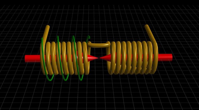
Consider for a moment the construction of the triode which includes the bifilar coils located within the fields of the two magnets.
When the current in one half of the conductors in the coils (i.e., one of the bifilar elements in each coil) of the device is moving up, both the current and the magnetic field follow the right-hand rule.
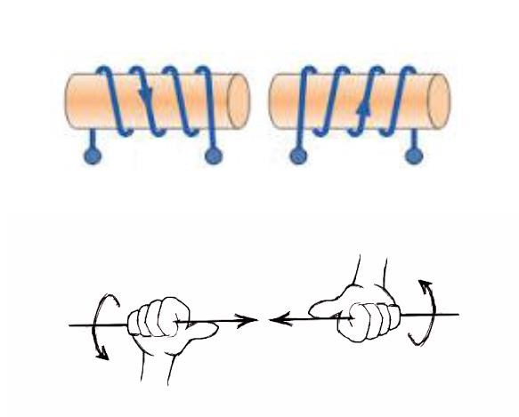
The resultant motional E-field would be vertical to both and inwardly directed.
At the same time the current in the other half of the conductors in the coils is moving down and both the current and magnetic field follow the right-hand rule.
The resulting motional E-field is again vertical to both and inwardly directed.
Thus, the resultant field intensity is double the intensity attributable to either one of the set of coil conductors taken singularly.
Newtons Laws of Motion
Pretty much the basis for Science today, Newton Invented Conventional Science in a very short time! However, the interpretation/understanding has been either been ignored or forgotten, if one knows about the true Story of Newton!
The Third Law currently reads:
For every Action there is an Equal and Opposite Reaction.
Is an incomplete statement, because this Law does not account for Systems that are NOT Symmetrical! In other words, Asymmetrical Systems, and there are many, the Symmetrical Law is inadequate to describe what truly occurs!
The Third Law needs to be amended to read:
For every Action there is an Equal and Opposite Reaction, and for every Reaction there is an Equal and Opposite Counter-Reaction.
now corrected, so that Asymmetrical Systems can be described accurately, we have a whole new half of Science that opens up for us!
Input Coil
Newtonian descriptor: Action
A Magnetic Field in the System: ΔΦB / Δt which Floyd Sweet referred to as "the excitation coil", this coil is a control mechanism, regulating System Frequency and bringing the System into Operation:
The Input Coil has some very unique properties when the System is running, it can very easily be shown, the Input Coils Impedance can change drastically, sometimes increasing in Impedance by thousands of Ohms! We have shown this many times here on this Forum!
POCOne
Newtonian descriptor: Reaction
A Magnetic Field in the System: ΔΦB / Δt, that can be measured, changing over Time t, that is a Source for Electromagnetic Induction to occur.
The combination of Turns, Load Impedance and the Voltage Generated gives you a Specific Magnetic Field Generated.
POCOne Generates POCTwos Voltage.
POCTwo
Newtonian descriptor: Counter-Reaction
A Magnetic Field in the System: ΔΦB / Δt, that can be measured, changing over Time t, that is a Source for Electromagnetic Induction to occur.
The combination of Turns, Load Impedance and the Voltage Generated gives you a Specific Magnetic Field Generated.
POCTwo Generates POCOnes Voltage.
Magnetic Resonance
POCOne and POCTwo must be in Magnetic Resonance! This means at time t, the Magnetic Fields of POC One and Two must always be Equal and Opposite! In Magnetic Resonance!
This requires the Turns, the Voltage and the Load Impedance all be equal in Magnitude!
When we have Magnetic Resonance, we have a standing Wave of Current, 2 x I, the Magnetic Fields B and H Cancel, if you do vector Math on them, and the Gate to the Dirac Sea is open, we have an Output Power, provided by the Motional Electromagnetic field: E.M.F = -ΔΦB/Δt
Observing Currents
When the Currents of POCOne and POCTwo are Equal but Opposite, then you know you have Magnetic Resonance, if:
- Turns are both the same.
- Load Resistance is both the same.
- Voltage Generated is the same.
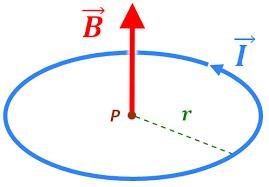
Defining a Magnetic Field in a Coil
The Turns N, Current I, Length L, Relative Permeability μr, and Permeability μ0, define the Magnetic Field using Amperes Law.
// Permeability:
Permeability = RelativePermeability * VacuumPermeability;

// Turn Density:
TurnDensity = N / L;

// Magnetic Field:
B = Permeability * TurnDensity * I;
Best Wishes,
Chris


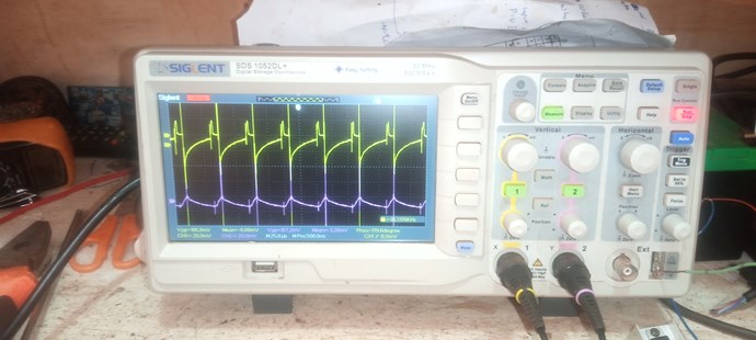


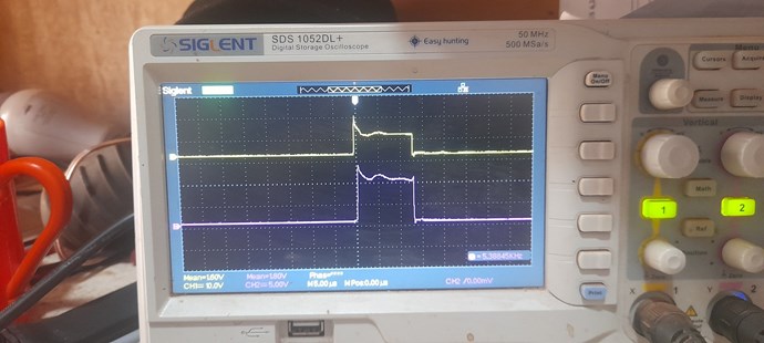
.jpg?width=690&upscale=false) I have a delay circuit that switches on L3, yellow trace is the pulse to the mosfet gate that switches L1 and the purple is the pulse to the mosfet gate that switches L3.
I have a delay circuit that switches on L3, yellow trace is the pulse to the mosfet gate that switches L1 and the purple is the pulse to the mosfet gate that switches L3.
 but it's tuned on "no delay" for now as shown below.
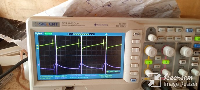
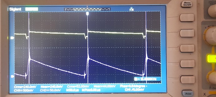
 Now moving the probes and looking at the currents through L2 and L3
I get these waves after some tuning, yellow trace is L2 and purple trace is L3.
Now moving the probes and looking at the currents through L2 and L3
I get these waves after some tuning, yellow trace is L2 and purple trace is L3.
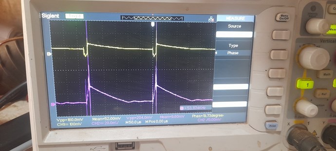 The sawtooth wave is not good here, the linear decrease on L3 is too fast, In an effort to get it better I tried many adjustments on input voltage frequency and duty cycle with no success, but when l grounded my scope i got a better sawtooth wave on L3.
 Iam i moving in the right direction? Please advise on what voltage value is to use RMS,Peak to peak or Mean?
Chris and the team thanks for sharing knowledge.
Iam i moving in the right direction? Please advise on what voltage value is to use RMS,Peak to peak or Mean?
Chris and the team thanks for sharing knowledge.


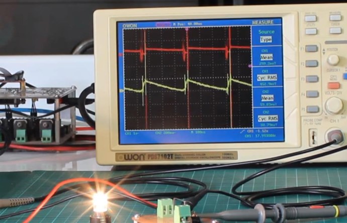
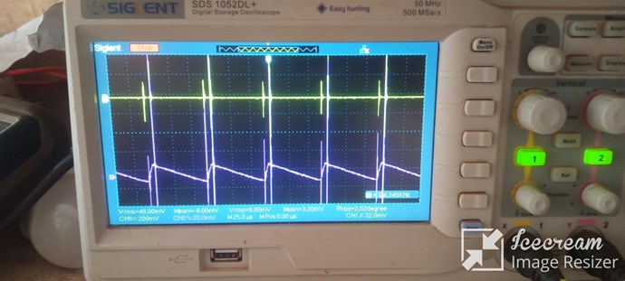
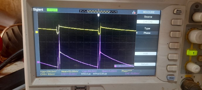
.jpg?width=690&upscale=false) After some adjustments on frequency, dutycycle and input voltage, I got the best sawtooth wave so far, the linear decrease ends at the right point at the end of the cycle and the input current drop effect was present.
After some adjustments on frequency, dutycycle and input voltage, I got the best sawtooth wave so far, the linear decrease ends at the right point at the end of the cycle and the input current drop effect was present.
.jpg?width=690&upscale=false)
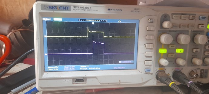
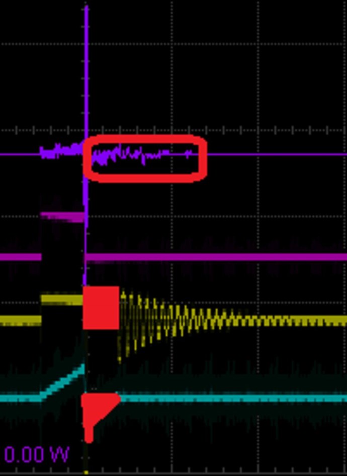
 Observation:
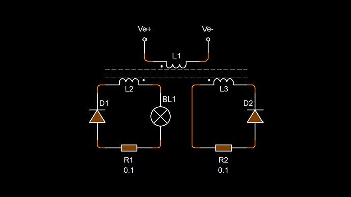
Switching in L3 i observed that the current iam measuring through L2 does not change. But the input current on the power supply drops.
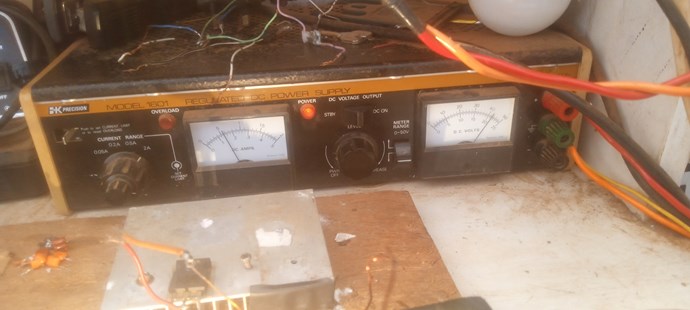
And the input current from the DC power supply powering the whole circuit is around 500ma.
The purple trace is showing current through L1 8volts across the resistor giving 8A !.i think its a wrong reading, please advise.
Observation:
Switching in L3 i observed that the current iam measuring through L2 does not change. But the input current on the power supply drops.
And the input current from the DC power supply powering the whole circuit is around 500ma.
The purple trace is showing current through L1 8volts across the resistor giving 8A !.i think its a wrong reading, please advise.
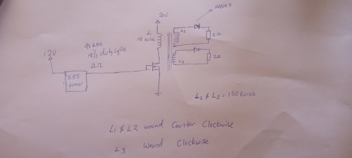
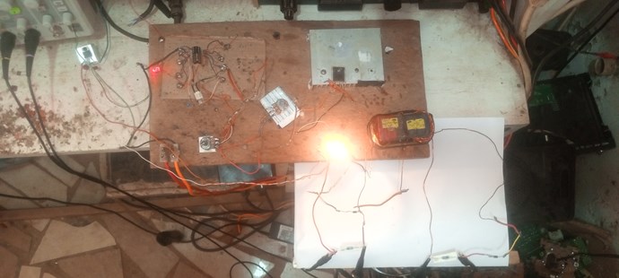
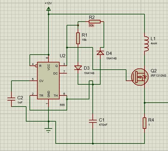 This is just for illustration how iam measuring the current through L1, R4 is the current sensor. Iam using a gate driver which is not included in shematic above.

.jpg?width=690&upscale=false)
.jpg?width=690&upscale=false)
.jpg?width=690&upscale=false)
.jpg?width=690&upscale=false)
-(1).jpg?width=690&upscale=false)


 I upgraded my switching circuit, replaced the mosfet with an IGBT.
 Current sensing resistors:
 I upgraded my 0.1 ohm wire wound non inductive resistor with this.
It's a non inductive cement resistor is not wire wound.
I upgraded my 0.1 ohm wire wound non inductive resistor with this.
It's a non inductive cement resistor is not wire wound.
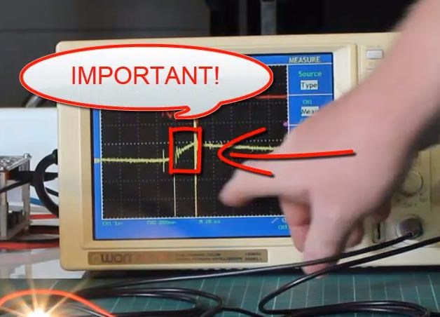
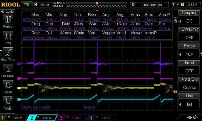
 Sawtooth wave on L3 isn't perfect but this is one of the sweet spots where I get what I consider to be the correct effect. "Input current drops and light brightens when L3 is switched on".
 Output voltage on the light bulb, and current through L2 Rms values;
 When L3 is connected, output voltage over the bulb goes up by 2 volts but output current through L2 does not change.
 Iam still experimenting focusing on delayed conduction in L3 with a goal to improve on the input current drop effect, advice on this will be appreciated.
thanks again for sharing knowedge.
Br.
Madscientist.
Iam still experimenting focusing on delayed conduction in L3 with a goal to improve on the input current drop effect, advice on this will be appreciated.
thanks again for sharing knowedge.
Br.
Madscientist.


