Chris
posted this
29 August 2025
- Last edited 29 August 2025
Hey MadScientist,
Thanks for sharing! Coming along nice! Good work there!
Your statement:
and iam still investigating on how to improve on this effect.
This is a very important thing for all researchers to ask!
Floyd Sweet made a very important statement:
We are all familiar with AM and FM propagation, where in the case as AM, the voltage amplitude varies, and with FM, the frequency is modulated. However, the output power sees a constant load impedance, that of the matched antenna system. If this changes, the input to the antenna is mismatched, and standing waves are generated resulting in a loss of power.
NOTE: The issue of confusion arises here because there is a difference between Standing Waves in a Single Wire and also the difference of an Electrical Standing Wave and a Magnetic Standing Wave. We need to have a Standing wave occur, but not in the same wire!
If you read this carefully:
If the directions of the two signals are such that opposite H-fields cancel and E-fields add, an apparently steady E-field will be created. The energy density of the fields remain as calculated above, but the value of the E-field will double from E/2 to E. It is a simple matter using the equations E/H = √με and C = 1/√με for a team wave to get rid of H and C and so convert the first equation into the well known equation for energy density in the so-called electrostatic field:
You will see Floyd Sweet refers to a Team Wave, which is the same as a Standing Wave, but under different underlaying conditions!
In each Wire, POCOne being one Wire and POCTwo being the Second Wire, each Wire has what I call Antenna Resonance, where the Length of the Wire requires exactly 1/2 Wave Length, and at Resonance, one end will be Peak Positive and the other end will be Peak Negative.
Between the Two Coils, each POC, there is a Magnetic Resonance, which means each POC is 180 degrees out of phase, Magnetic Fields Opposing, so, using the Right Hand Grip Rule, we will have Each Peak Voltage Difference is opposite. This we have already shown in experiments.
Its important, we must find the Magnetic Resonance, basically:
Use the Formula:
- Approximate Formula: Length (meters) = 143 / f (MHz) ( 1/4 Wavelength ) 142.65 is more accurate! NOTE, this is not Half Wave!
- More Precise Formula: Length (meters) = 300 / f (MHz) ( Full Wavelength )
Example:
- 143 / 0.003 = 47,666.67 Meters
This is not a very useful example, because 47,666.67 Meters of wire on POCOne and POCTwo is simply not practical!
A better number would be 30 meters for example! So rearranging the equation gives us: f (MHz) = 143 / meters = 143 / 30 = 4.77 MHz, and the 4th harmonic is 4.77MHz x 4 = 19.08MHz and the length of this coil, your Input Coil, will be: 143 / 19.08MHz = 7.49 meters.
Tom Bearden said:
Hmm, Over Gain One, at Resonance... Yes Sir, we have seen this already.
Best Wishes,
Chris


.jpg?width=690&upscale=false)


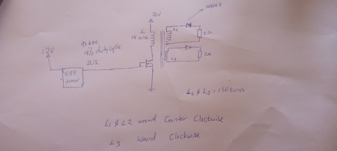
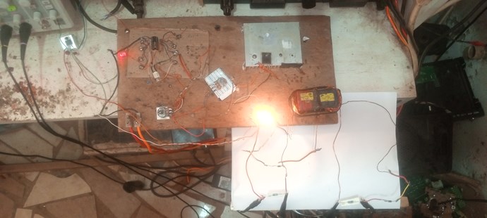
 It's the same circuit, "Chris's circuit" and I have made some minor changes on my coils, using thicker wires little noticeable results but when I hooked up a 25W 250V light bulb, i noticed some increase in input current drop at a specific frequency around 100khz.


