Chris
posted this
15 September 2019
- Last edited 15 September 2019
Ok, My Friends,
What are we missing? What's not on this thread?
Ok, so, Scientifically, what do we know.
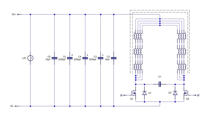
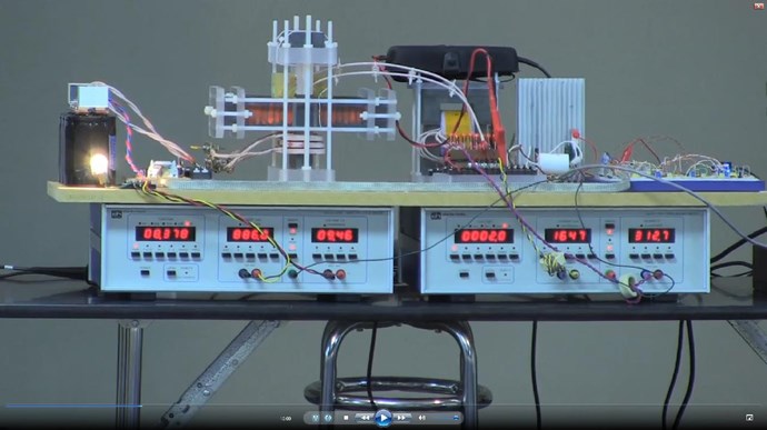
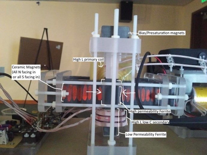
1: Input Winding appears to be 10, 12, 10, 12, 10, 12, possibly only 6 layers, of Litz Wire, about AWG 2 (6.54304 mm) @ approx 0.512664 Ohms per KM.
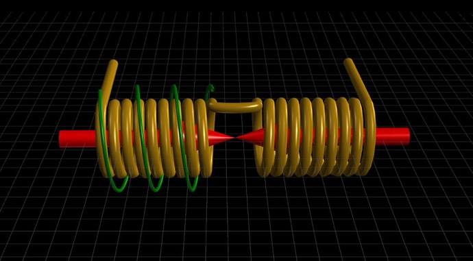
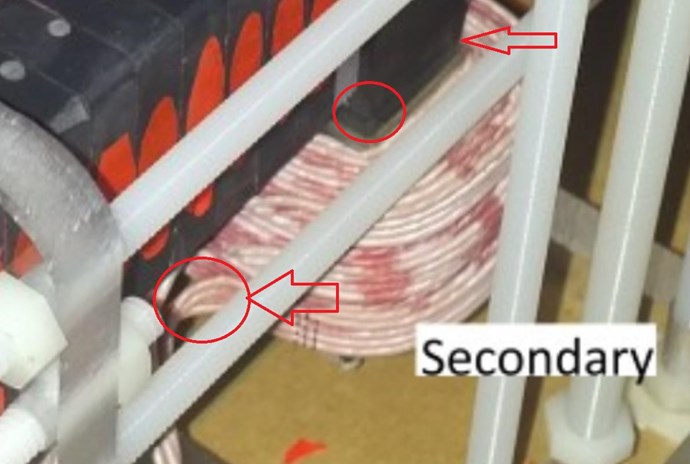
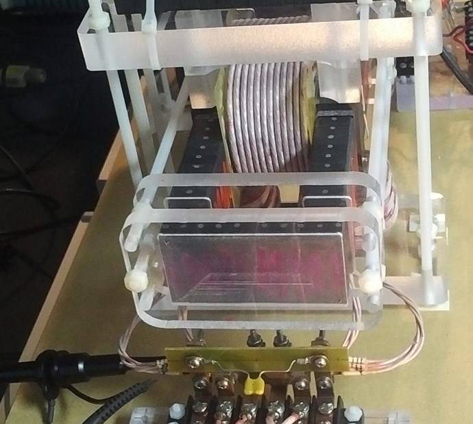
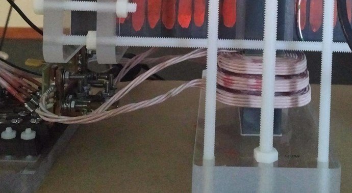
2: Output Coils consist of 4 Strands of Litz wire, each wound side by side, in a step winding configuration, Almost Bank Winding. Each set of winding's is divided into two parts. Each set of windings appear to be wound CW/CCW relative to the Core.
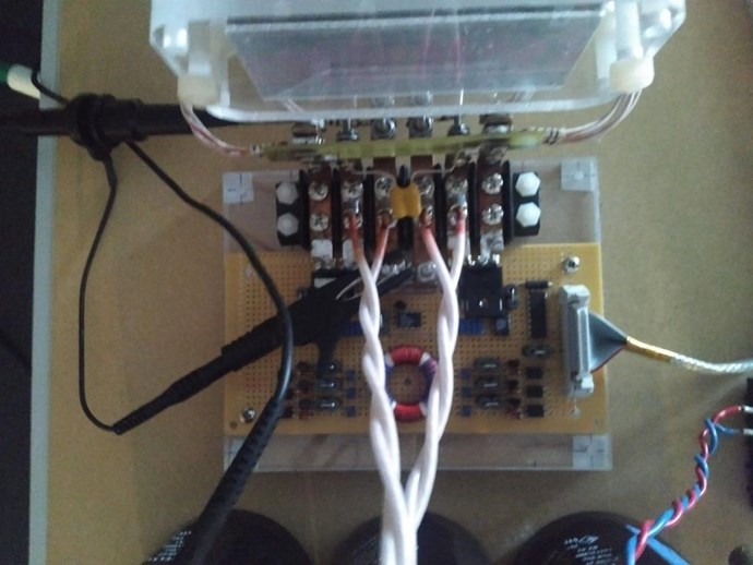
3: Output is DC, Rectified, via a circuit arrangement of possible 30 odd components.
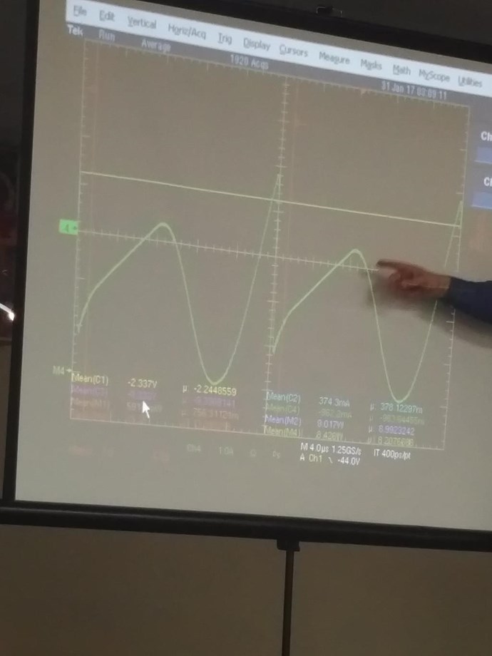
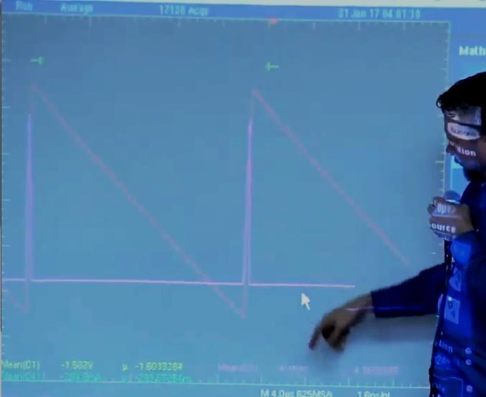
4: Pulsed DC is the Input. As Reiyuki points out, about 33% 33% 33%
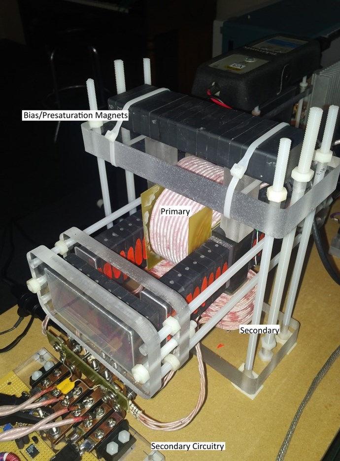
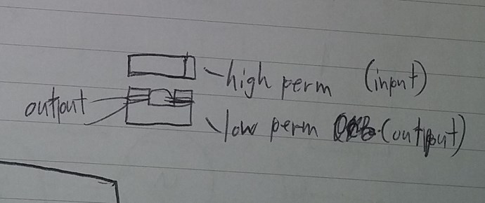
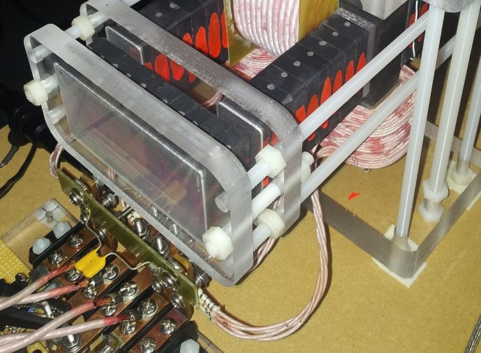
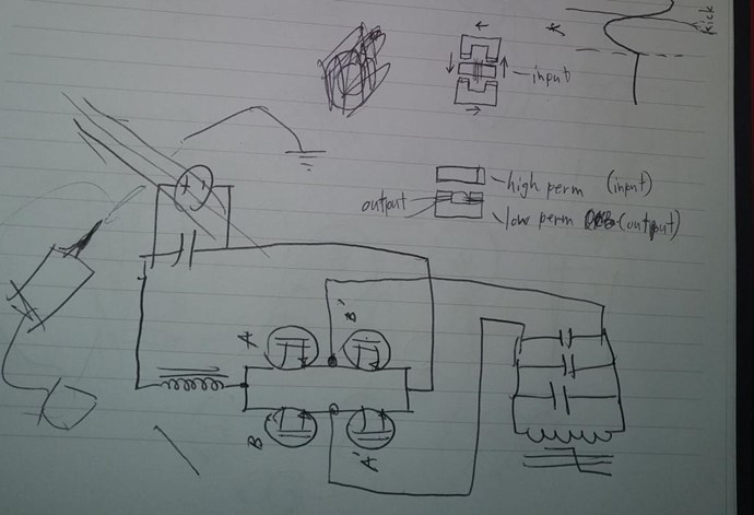
5: Permanent Magnets are arranged on the Device, thought to Bias, or partially saturate at least one half of the U Cores used.
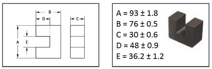
6: U Cores are a Ferrite Material, apparently each has a different value of Permeability. No specifics that I know about have been shared as yet. (The below product guide, has an AL range from: 2300 to: 8700 (nH measured in combination with another ungapped core half))
7: U Core appears to be approximately square, a product selection guide can be found here: Ferroxcube, the largest U Core in this document is in the Picture below: (Which is about right, I have some magnets the same here (25 x 40 x 10) and they would fit about the same on the Core)
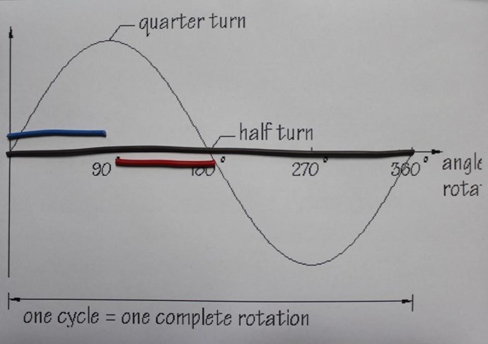
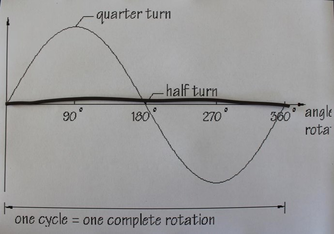
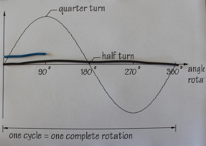
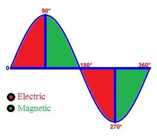
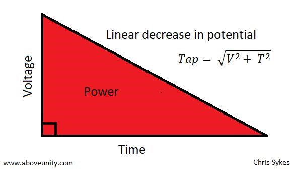
All in all, what’s the Key concept here? Time Rate of Change of the Magnetic Flux, and the second key point is there are Two Output Coils, arranged specifically in separate space on the second half of the U Core. Electricity is the end result of Electromagnetic Induction, time rate of change, where in the Input Coil is the Prime Mover, which is mostly or completely unaffected by the Drawing of Current on the Output.
Ref: Graham Gunderson's Energy conference presentation
Another:
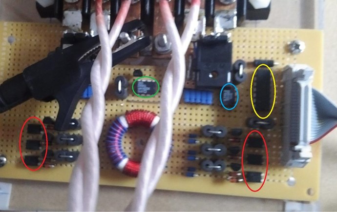
Thanks to Reiyuki's awesome documentation efforts, and for others out there interested, I have done some ID'ing on the IC's
I believe all the Opto's are the same, as the surrounding circuitry is the same. Some appears to be redundant, I may be wrong however.
Red Circles: NEC PS 2505
Green Circle: IXDD614PI
Blue Circle: IL710
Yellow Circle: 74AC14PCX
Please check for yourself, I am not 100% sure on all of them, if is very close if I have not got it spot on.
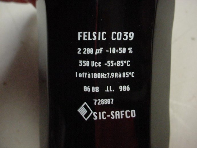
The Output Caps:
3 x Felsic Aluminum Electrolytic Screw Capacitor 2200µF 350Vcc
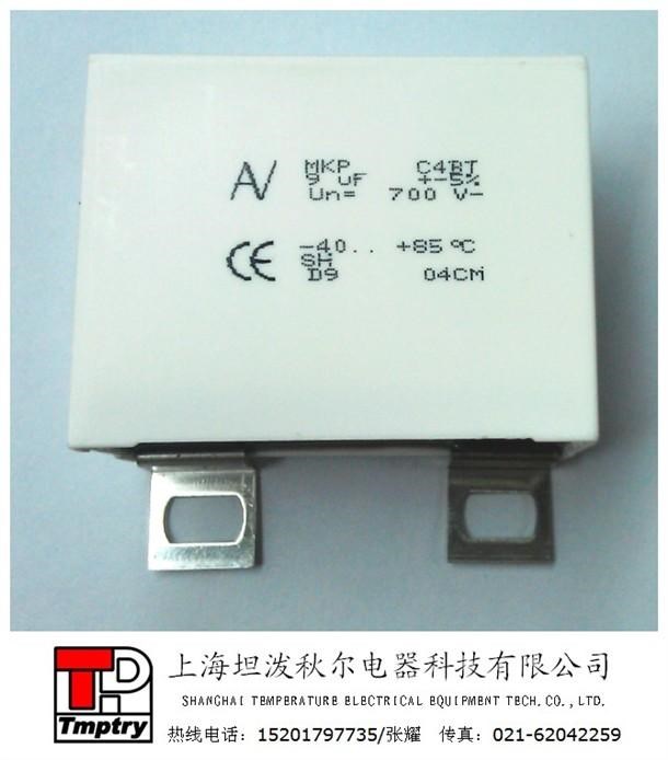
2 x Kemet Arcotronics AV MKP C4BTHBX5100Z_L_ Style A 10uf 600V
This is a lot of ciruitry for Synchronous Rectification, Texas Instrunemts has a good doc on this, that is, if this is what Graham is doing?
Ref: Graham Gunderson's Energy conference presentation
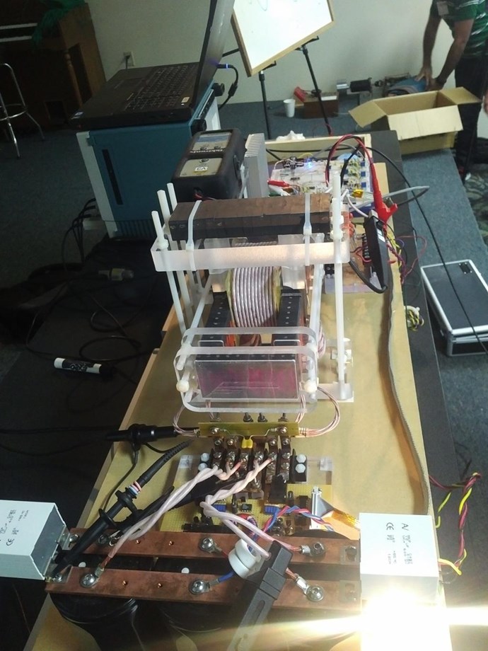
So, basic parts list is now built. We have Bias Magnets also.
We have a Gapped Input Core, compared to the Closer Coupled Output Coils on the same core! Partnered Output Coils! Partnered Output Coils are on the same Core!
So what, if anything, do we have here that is remarkable? We have nothing remarkable!
Whats going on? Its the timed interactions of the Partnered Output Coils!

Ask yourself: What is the timed interactions of the Partnered Output Coils? Why, what does this timing do? What are the fundamental rules of Electromagnetic Induction?
A lot of this has been covered in the thread: Important: Delayed Conduction in Bucking Coils
Datasheets below:
Chris


-small.jpg?width=690&upscale=false)