My MrPreva Experiment Replication

  • 931 Views
  • Last Post 16 December 2023
FringeIdeas posted this 24 April 2023

Ok, I hope I got this all correct. I actually tried posting this to the end of the existing MrPreva discussion, but it wouldn't post for some reason, so I'll just start another. Finally got my scope and generator. Measurements are a bit off because my 0.1 ohm resistors were home made by a friend. Close, but not precision. Anyway, the effect was still clear. Here are the details and a video explaining it all. If I screwed something up, let me know. Positive criticism is always welcome. I'll keep going through the builders guide and try to decide what experiment to follow up on next.


Order By: Standard | Newest | Votes
FringeIdeas posted this 24 April 2023

Man, could not embed the YouTube video, but added a link and it embedded it.. 😀 Ok, all ended well, pics and video posted. Time to clean the bench.

Chris posted this 25 April 2023

Very nice work FringeIdeas!

I left a message and a +1 on your video. 

On the right hand side, see the link:

 Help with using the Forum.

Hope this helps!

Best Wishes,

   Chris

FringeIdeas posted this 26 April 2023

Hey Chris, I saw the comment on the video, point received. And thanks, I appreciate the help and positivity!

Marcel

FringeIdeas posted this 01 December 2023

Chris, or anyone with a suggestion. I've been wanting to step through this experiment again just to get more familiar with it. Winding ratios, what happens when one coil is on top of the other, etc. Just play around and post results.

I've ordered some small hobby amp three times now. Hook it all up, and as soon as I connect my scope lead ground the whole thing goes dead. My last amp I got, some Kenwood car audio amp, had in the manual that it was BTL (bridge tied load). This is the first time I've heard of this to be honest. So two comparators, one inverted, one not, for each output. Basically a floating output, and connecting ground kills everything.

So, the question, I know there was a link from Chris to an amplifier, but I remember checking and it was not sold anymore. So does anyone have any cheap suggestions for a non-BTL amp that works for this experiment? I considered floating my scope ground, but aside from possible measurement errors I think that might be a bit dangerous.

Side note: Next week I should get bobbins delivered. I also plan to step through the some coils buck and some coils don't experiments. Seems like something one should experience for themselves. And my "FringeIdeas Non-Inductive Coil Experiment Replication" should continue soon as well. I had found a bit of resonance and the effect of poc2 assisting the input, but thinking I could make the effect better I ended up screwing it all up. So I'm doubling my core width, and have new bobbins coming for that as well. Should be able to show the effect once I get the coils wound. At least I know what I'm looking for now.

Ok, any help with the amp issue would be fantastic, much appreciated!

Marcel

  • Liked by
  • Chris
  • Augenblick
Chris posted this 01 December 2023

Hey Marcel,

Excellent post My Friend!

The answer to this post is: You need to have a good understanding of the Processes occurring in the initial experiment, to be able to make improvements.

Question: "How is POCTwo's Voltage Generated?" and "How can we improve, and Generate more Voltage?"

General rule of thumb, for Partnered Output Coils, is Coil Geometry, because, the Magnetic Field has properties that can be used to gain an advantage in the operation of our machines.

Energy Density depends entirely on the Magnetic Field Strength, a close link here to fundamental processes!

The links in this post will give you all the info you need!

Best Wishes,

   Chris

FringeIdeas posted this 02 December 2023

Thanks Chris, I will indeed dig into those links! I need to find a non-BTL type amp. Hopefully soon. So if anyone has a recommendation for an amp that works for this experiment, don't hesitate to let me know.

Cold and dark here in Finland. Time for a little Netflix with the wife, I'll get to those threads in the morning.

Thanks again!

Marcel

  • Liked by
  • Chris
  • Augenblick
Chris posted this 02 December 2023

Hey Marcel,

An Audio Amp is very useful for experiments, that's for sure!

I use a Sony Xplod, 1000 Watt:


But thing is with Amps, is you need to understand that they are designed for 2, 4 and 8 Ohm Load Impedances, typically.

So your Coil, that you're driving sort of needs to come close to the Output Impedance, or the amp will go into Overload or break a fuse, or worse and Smoke it.

Best Wishes,

   Chris

  • Liked by
  • Augenblick
  • FringeIdeas
FringeIdeas posted this 03 December 2023

Awesome thanks! The impedance issue I kind of expected. Let's see what I can come up with. Hopefully messing around on the bench soon. Thanks again!

Marcel

  • Liked by
  • Chris
  • Augenblick
FringeIdeas posted this 07 December 2023

Ok, so I looked around for used audio amps that fit the bill, but could not find anything suitable. I ended up with this.

Kemo M033N. Loudspeaker amp, so one channel. Speaker negative tied to ground, so no BTL (bridge tied load), meaning I can scope it without killing the signal. Win. Output impedance range of 4-16 ohm.

I played around with it for a while. Signal over a bulb shows no attenuation until around 50KHz, another win.

Here is the basic schematic of what I have set up now.

So this time, series cap, and a bulb in series with each coil.

Here is a pic of the setup


Toroid transformer core, two coils, one cw one ccw, 65 turns of 1mm each. Not sure I like the core to be honest, but the Blippi colors make it all worth it. Let's see how it works for the experiments.

L1 and L2 are around 0.3 ohm, 85 µH (calculated because my meter seems to be broken). Fres of each coil is around 4 KHz. Bulbs are between 15 and 18 ohms, somewhere around there, depending on brightness of course.

The plan is, starting tomorrow morning, probably going into next week, to run through a set of measurement and observation steps. Then remove 5 turns from one of the coils and repeat the steps, until that coil is down to nothing.

The steps being:

  • Current in each leg and total circuit current.
  • Voltage over each bulb.
  • Max phase shifts, if any, and what frequency they are occurring.

If I'm missing something I should be paying attention to, please let me know.

Ok, bed time here. Fun fun fun in the morning, hopefully it's a slow work day.

Br,

Marcel

  • Liked by
  • Chris
  • Augenblick
FringeIdeas posted this 12 December 2023

Hey, so I'm still testing but wanted to at least share where I'm at. This week I actually ran through my tests twice. Second time, which I will share, is only the turn ratios that produced the 180' out of phase. Which turned out to be many more than I expected. Maybe the core, not sure.

Again, starting with 65 turns I took measurements then removed turns, then took measurements again, repeat until the effect does not show up anymore.

The fields marked in red are the current measurements. Input, L1, then L2. Like before, and in many other replications, it's quite easy to see L1 with reverse current, and L2 (which I was removing turns from) maintains around double the input current. Voltages are knocked down, as expected.

Here is a quick pic of the L2 bulb being brighter than the L1 bulb.

The bulb started getting brighter at around 50 turns. At this point in the picture, with 30 turns and a lot less impedance, I'm sure no current was interested in running through L1 anyway 🙂 But still, 180' out of phase, much more current on L2.

I will run through this test on a different core though. I have a flyback transformer core I'd like to use. The reason being is I still have questions. I would have really loved to see a defined resonant peak in the individual coils, which correlated with the effect. I'm assuming it's L1 that goes into resonance when the effect shows up, but that is an assumption still for now. This core and setup performed like an extremely wide band pass filter, so it was difficult to tell.

Hopefully I can wrap this up before the weekend, lets see.

Thanks!

Marcel

  • Liked by
  • Augenblick
  • strape
FringeIdeas posted this 14 December 2023

Chris, one small thing I'm struggling to grasp, if you could help.

One of the reasons I'm going through Me Preva again is to understand the 180' flip of phase and amplification. The cos(180) =  -1 power factor I get. So that is what is adding to the other current. Makes sense. ref for the readers, very beginning of the thread the-mr-preva-experiment

In the specific case of positive charges moving to the right and negative charges to the left, the effect of both actions is positive charge moving to the right.

Current to the right is: I = da+ / dt + da- / dt.


Negative electrons flowing to the left contribute to the current flowing to the right.

But how is this 180' of shift occuring in the first place? I assumed it was just the nature of resonance, but in reading a bit it seems resonance in a coil brings input/tank voltage from 90' out of phase to in-phase, and current from in-phase to 90' out of phase.

So, only one of the coils in the Mr Preva setup is finding resonance correct? Or are both? I'd would imagine that they would have a difference Fres. So where is the other 90' of shift coming from for the current?

I have managed to wind one coil today, and played around with resonance and phase shifts, and it appears to be like what I read.

I know I'm having a senior moment, it's something simple I'm overlooking, but can't seem to figure this one out.

Thanks!

Marcel

Chris posted this 14 December 2023

Morning Marcel,

Your posts are always sensible and logical, I thank you for your very good posts, its a pleasure having a dialog with you!

Chris, one small thing I'm struggling to grasp, if you could help.


I will do the best I can Marcel!

One of the reasons I'm going through Me Preva again is to understand the 180' flip of phase and amplification. The cos(180) =  -1 power factor I get. So that is what is adding to the other current. Makes sense. ref for the readers, very beginning of the thread the-mr-preva-experiment

In the specific case of positive charges moving to the right and negative charges to the left, the effect of both actions is positive charge moving to the right.

Current to the right is: I = da+ / dt + da- / dt.


Negative electrons flowing to the left contribute to the current flowing to the right.


Yes, exactly right, Sourcing a Current, or Sinking a Current is the key, and as you point out, Cos( 180 ) = -1, this gives us the hint, and the Four Quadrant Argand Diagram gives us the answer:


Positive effective Power has a Power Factor of Cos( 0 ) = 1, a positive number, and in the X Direction of Quadrant One, thus power is being delivered to the load and used in the Load.


But how is this 180' of shift occuring in the first place? I assumed it was just the nature of resonance, but in reading a bit it seems resonance in a coil brings input/tank voltage from 90' out of phase to in-phase, and current from in-phase to 90' out of phase.


This is a great question! 

In the thread: "Polarity of a Generated E.M.F.", I pointed out:

NOTE: A Generated Voltage is in the opposite direction compared to an applied Voltage, so please remember this!


We can do some circuit analysis to see what works, the same way, as The Mr Preva Experiment, and to some peoples surprise:

Once one understands, that the only exception for Kirchhoff's Current Law KCL, is when a Current Source is present, we can assume this to be the case, before we do the necessary circuit analysis.

KCL is a very definitive Law, useful:

Kirchhoff's current law (KCL) states that the algebraic sum of branch currents flowing into and out of a node is equal to zero. This is an outcome of the principle of the conservation of electric charge. If any new charge enters a node some equal amount of charge must exit.


As you can see, this Law does not hold, in The Mr Preva Experiment. Now we know why, its very easy to explain, but it requires some base knowledge and as you are doing, some experiment, to understand this amazing Circuit.

NOTE: Always, the Coil with more turns is the Coil we see a reversal of Current, because the "Generated" Voltage is Higher, for example, if B1 Voltage is higher than B2, we do not see this same result:


So, only one of the coils in the Mr Preva setup is finding resonance correct? Or are both? I'd would imagine that they would have a difference Fres. So where is the other 90' of shift coming from for the current?


Another very good question!

I think there is a Balance of the two Coils, if we add the Inductances, then divide by 2, then we get a pretty close equation for the LCR Resonance. I do not have a definitive answer on this however.

Note: This is the ultimate experiment, showing and proving Magnetic Resonance. Magnetic Resonance is not the same as LCR Resonance, because the Magnetic Fields, in "Generating" an E.M.F, which results in Currents being 180 Degrees out of Phase and approximately equal in Amplitude is key to understanding Resonant Electromagnetic Induction.

I have managed to wind one coil today, and played around with resonance and phase shifts, and it appears to be like what I read.

I know I'm having a senior moment, it's something simple I'm overlooking, but can't seem to figure this one out.

Thanks!

Marcel


I very much enjoy "Problem Solving", it is something I have always enjoyed. Not to say I am good at it, just saying I really do spend a lot of time looking for the most simple answer to the most complex problems.

My Friend, turning a few Simple Coils into an Energy "Generator" is our expertise, that's why we are Light Years Ahead of the others! We truly are!


The others, they are still stuck in their Year 3 Lunch Bags!

Its always a pleasure having Dialog with you Marcel! Thank You!

Best Wishes,

   Chris

  • Liked by
  • Augenblick
  • strape
FringeIdeas posted this 15 December 2023

Hey Chris, thanks for the kind comments, it's mutual, and I appreciate the detailed answers.

The Polarity of a generated EMF is something I understood, but didn't consider. The generation of the voltage on the coil with more turns is generated from the other coil I assume. But in which way? Turn ratio? Meaning, we can look at the smaller coil being an input to a step-up transformer with the larger coil being the secondary?

The frequency and average of inductance I will keep an eye out for. Right now it doesn't seem to correlate with anything really. But I'll figure that out.

There is a lot to learn here, pretty cool little experiment. I got the second coil wound and started messing around with it today.

Both coils 80 turns of 0.8mm. Started off at about 13.5 mH for both. Started taking off turns to watch the progression of the phase shift. Stopped because of lack of time around 40 turns. It's close to 180' out of phase, but not exact. But the effect is visible at this point already. The smaller coil bulb is quite bright compared and the numbers are similar to before. Input A + L1 A = L2 A, if I got that right.

Lots going on this weekend, so I won't be able to get back to this until Monday, but I might take off a few more turns, or just turn it on and stare with my right hand thumb flip flopping around. Definitely putting some thought into this though, very interesting, and I appreciate the help.

Thanks!
Marcel

FringeIdeas posted this 16 December 2023

Hey, so the more I thought about this setup, the more it made sense, what you said about the dominating generated voltage on the bigger coil. I took a quick sneak away from the family this morning, checked voltages, and what you said lined up. 80:40 turn ratio. Smaller coil was around 3.7 V, larger coil was around 7.4 V, and the input around 6.5. Funny, So the magnetic field in the bigger coil is generated by the smaller coil, reversed current, resulting in bucking magnetic fields and current amplification.

Here we are trying to understand the way coils and magnetic fields interact together, and i totally stepped over that one. 😂 Let's call that my senior moment.

So this setup makes sense now. And it filled a rabbit hole I had dug for myself. To be completely transparent, during the non-inductive coil experiments, I had convinced myself that I should be seeing a reversal of current at some point. So now I understand that this setup, Mr Preva, creating the reversal of current, is one of many ways to achieve opposing magnetic fields. The non-inductive experiments does not use this method, rather it's simply the diode configuration that dictates the magnetic field directions, and I am not to expect a reversal of current anywhere there. Rabbit hole filled, check in the box.

Main take-aways:

  • No reversal of current expected in the non-inductive experiments.
  • Opposing magnetic fields amplify current.
  • Voltage is knocked down quite a bit during magnetic field bucking, so methods need to be used to accommodate that.

Monday I might look a bit more on the frequency thing to see why it resonates at the frequency it does, but I've learned what I wanted to find out, and more. So I'll call this thread a success and done. Next week I'll rewind a few coils and start the experiments of some coils buck and some coils don't.

Just for a smile..

Fantastic win, I appreciate all the help!

Marcel

Chris posted this 16 December 2023

Hey Marcel,

My Friend, an excellent, very fitting funny there! I like it!

Yes, our minds do play tricks on us, when you say:

I had convinced myself that I should be seeing a reversal of current at some point. 


I agree, my mind has done the same, but because we make very strict, detailed observations, and circuit analysis, we can prove our mind tricks wrong, because there is always an explanation for what we see!

Your Statements:

Main take-aways:

  • No reversal of current expected in the non-inductive experiments.
  • Opposing magnetic fields amplify current.
  • Voltage is knocked down quite a bit during magnetic field bucking, so methods need to be used to accommodate that.


Absolutely!

IMPORTANT: I have learned, the hard way, never Assume, Never look for or incorporate any Magic in your research! Never believe others, including myself, always check and verify everything! There is ALWAYS a perfectly good explanation to what we see on the bench! It is OUR JOB, to observe, study, and explain these things properly!

There is NO Magic, they would have you believe otherwise, but there is no magic here! The Coils behave in a very predictable way! There is nothing occurring that can not be predicted, once the correct understanding is achieved! 

Exactly, Opposing Magnetic Fields, Amplify Current! That's absolutely spot on!

My Friend, the last bullet point, this is a very interesting and a very important aspect and this needs a lot of attention to more broadly understand!

I said, in the Thread: Voltage:

From the early days, we have had problems with Voltage! At one point I asked the question in one of my Mr Preva Experiments, why such a large Voltage Drop?


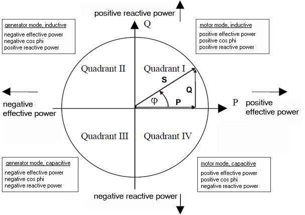
First: A Voltage is either:

  1. Generated - Example: " Electric Generator"
  2. Un-Generated - Example "Common Mode Choke"


The "Potential Difference" of Charge between Terminal TOne and TTwo, the total Elementary Charge's, the Difference in Number, can be Balanced, in Number or Distribution, and due to our beautiful principal, Superposition, we can Cancel out the Charge Difference, or we can double, the total Number.

For Example:

  • POCOne has 10 Volts "Generated".
  • POCTwo has 10 Volts "Generated".


The Polarity of this voltage can be predicted using the Right Hand Grip Rule, and thus if we make a Conscious decision to Wire these coils in convention Bucking Mode, we end up with a total Voltage of Zero! Because 10V + -10V = 0V!

However, A Hint in the Literature, one I have tried to get out there for quite some time, is:

If the directions of the two signals are such that opposite H-fields cancel and E-fields add, an apparently steady E-field will be created. The energy density of the fields remain as calculated above, but the value of the E-field will double from E/2 to E.

Ref: Floyd Sweet - Nothing is Something.


Floyd Sweet tells us, the Electric Field Intensity can double, from E/2, a Singular "Generated" Potential Difference of E, to a more useful E, thus E/2 + E/2 = E. 

Again, back to our example, 

  • POCOne has 10 Volts "Generated". E = 10 Volts.
  • POCTwo has 10 Volts "Generated". E = 10 Volts.


In this beautifully simple circuit:

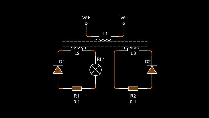
You can see, I have implemented and loaded e/2, individually, in each separate Circuit, Diakoptics, and although one appears to have no load, truth is, it is fully loaded, with a Load Resistance of minimum value.

This circuit represents Asymmetrical Electromagnetic Induction, we have a Voltage "Generated" in the System more than once, and we have three separate Magnetic Fields, all working in the System at the same time.

This experiment, and the above circuit, proves, Electromagnetic Induction is Incomplete! Electromagnetic Induction works! No one can deny this! However, it is an incomplete field and no one has ever corrected it, nearly 200 Years and no one has ever come forward with a completed and working Electromagnetic Induction, I have completed it, its now complete, and this is the answer to all of the worlds problems!

Anyway, Voltage must be "Generated", and it is the Interaction of the Coils on each other, that either "Generates" or "Un-Generates" the Voltages! Voltage is Regulated by the applied Negative Voltage.

Bucking Magnetic Fields "Generates" Voltages and Pumps Current!

Again, Marcel, its wonderful having such advanced dialog with you! You are very thorough and I see you understand all of this, but are just putting the pieces of the puzzle together. I respect that!

NOTE: EVERYONE should be Replicating and Studding, this very important information! Its all about Understanding! Once you understand, the rest is very very easy! This is SO IMPORTANT!!!

Best Wishes,

   Chris

We're Light Years Ahead!
Members Online:
What is a Scalar:

In physics, scalars are physical quantities that are unaffected by changes to a vector space basis. Scalars are often accompanied by units of measurement, as in "10 cm". Examples of scalar quantities are mass, distance, charge, volume, time, speed, and the magnitude of physical vectors in general.

You need to forget the Non-Sense that some spout with out knowing the actual Definition of the word Scalar! Some people talk absolute Bull Sh*t!

The pressure P in the formula P = pgh, pgh is a scalar that tells you the amount of this squashing force per unit area in a fluid.

A Scalar, having both direction and magnitude, can be anything! The Magnetic Field, a Charge moving, yet some Numb Nuts think it means Magic Science!

Message from God:

Hello my children. This is Yahweh, the one true Lord. You have found creation's secret. Now share it peacefully with the world.

Ref: Message from God written inside the Human Genome

God be in my head, and in my thinking.

God be in my eyes, and in my looking.

God be in my mouth, and in my speaking.

Oh, God be in my heart, and in my understanding.

Your Support:

More than anything else, your contributions to this forum are most important! We are trying to actively get all visitors involved, but we do only have a few main contributors, which are very much appreciated! If you would like to see more pages with more detailed experiments and answers, perhaps a contribution of another type maybe possible:

PayPal De-Platformed me!

They REFUSE to tell me why!

We now use Wise!

Donate
Use E-Mail: Chris at aboveunity.com

The content I am sharing is not only unique, but is changing the world as we know it! Please Support Us!

Thank You So Much!

Weeks High Earners:
The great Nikola Tesla:

Ere many generations pass, our machinery will be driven by a power obtainable at any point of the universe. This idea is not novel. Men have been led to it long ago by instinct or reason. It has been expressed in many ways, and in many places, in the history of old and new. We find it in the delightful myth of Antheus, who drives power from the earth; we find it among the subtle speculations of one of your splendid mathematicians, and in many hints and statements of thinkers of the present time. Throughout space there is energy. Is this energy static or kinetic? If static, our hopes are in vain; if kinetic - and this we know it is for certain - then it is a mere question of time when men will succeed in attaching their machinery to the very wheelwork of nature.

Experiments With Alternate Currents Of High Potential And High Frequency (February 1892).

Close