My Friends,
In the beginning, cursed with limited knowledge, I fumbled with the terms and diagrams of Floyd Sweet and others. Also taking note of other devices like Paul Raymond Jensen, Lester Hendershot and others, after some time I saw some common themes and base concepts.
Think Simple was my saviour!
Voltage
Voltage is Elementary Charge, separated, creating a difference in Charge Potential on Each Terminal.
A concept requiring Conductance ( G ) = 1 / Resistance ( R )
Current
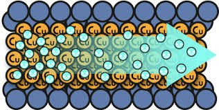
A flow of Elementary Charge, originally defined as 6.24 1018 electrons per second past point P1 equaling 1 Ampere of Current. Current must be Pumped exactly the same as Water must be pumped to create a flow. Electrons in a Wire have Velocity, depending on the composition of the Wire, it can be close to the Speed of Light.
Also a concept requiring Conductance ( G ) = 1 / Resistance ( R )
Note: The closest analogy to Electrical Energy is Pumping Water through a Pipe!
Note: Kinetic Energy is the elementary motion of a body or bodies. Newtons, force = mass times acceleration.
Ere many generations pass, our machinery will be driven by a power obtainable at any point of the universe. This idea is not novel. Men have been led to it long ago by instinct or reason; it has been expressed in many ways, and in many places, in the history of old and new. We find it in the delightful myth of Antheus, who derives power from the earth; we find it among the subtle speculations of one of your splendid mathematicians and in many hints and statements of thinkers of the present time. Throughout space there is energy. Is this energy static or kinetic! If static our hopes are in vain; if kinetic — and this we know it is, for certain — then it is a mere question of time when men will succeed in attaching their machinery to the very wheelwork of nature.
- Nikola Tesla, "Experiments With Alternate Currents Of High Potential And High Frequency" (February 1892)
Take a length of Wire:

Immerse this Length of Wire in a Sinusoidaly Changing Magnetic Field.
We know and experimentally can prove, the Terminals, not shown, will have an E.M.F, Electromotive Force, or a Voltage will be Induced determined by: E.M.F = -N dΦ/dt
It can be experimentally proven that the Currents and Voltages will have a specific Polarity and Phase that is unchanging between the two Parallel Wires at all points during the Cycle.
It also can be proven that the Currents will be travelling in the same direction at all points during the Cycle. No matter what winding polarity is used - This is the result of the Driven Force Pumping the Current.
At no point during the cycle, do the Parallel Wires Buck each other.
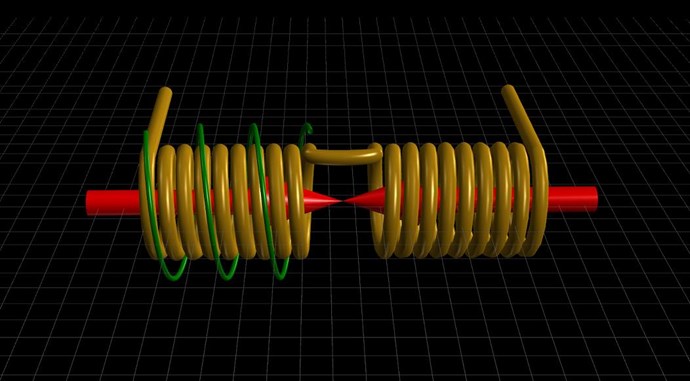
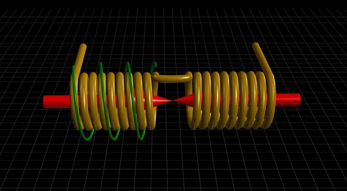
We have seen, some Transformers are wound with bifilar Coils, as a method of doubling the Current with less total wire area:
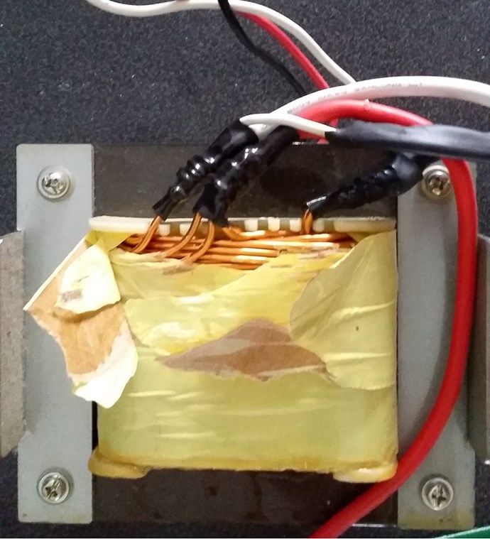
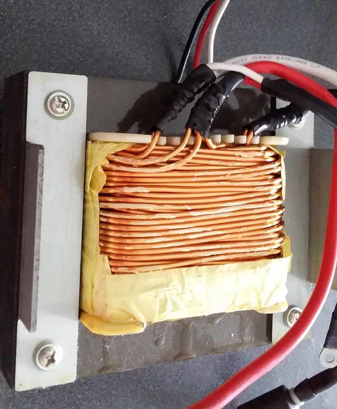
This is not a Natural State for Parallel Wires when a Changing Magnetic Field is present!
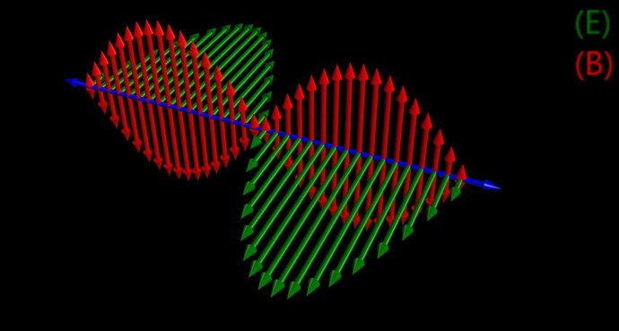
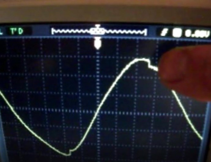
A sinusoidal waveform can be shown to contain Electric and Magnetic individual components at different times:
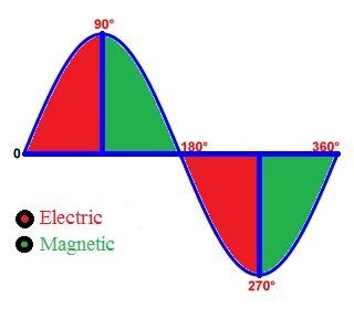
This knowledge is critical knowledge to have and understand. Why? Because we have a means, in every aspect, to simulate an Electrical "Generator" using three things:
- A source Magnetic Field changing in Time t. Not yet shown. Area shaded Green above.
- Conductors with an Induced E.M.F and as a result potential for Current to Flow.
- A means to Pump Current without adversely affecting the Input Source Magnetic Field.
Now what device do we know of that can Isolate Conductivity at a specific point in the Cycle shown above? Most of you no doubt will have an epiphany at this stage.
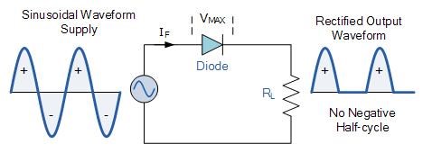
A Triac is capable of Conducting at a specific Point in the Cycle.
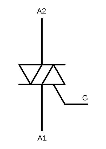
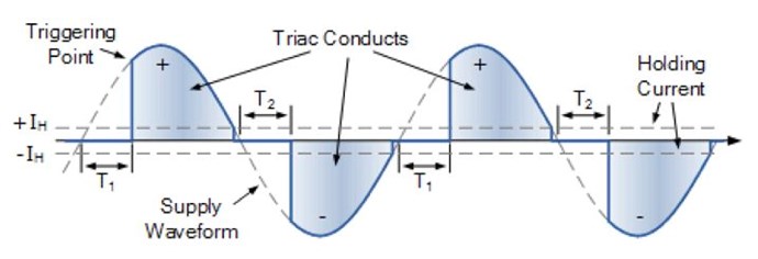
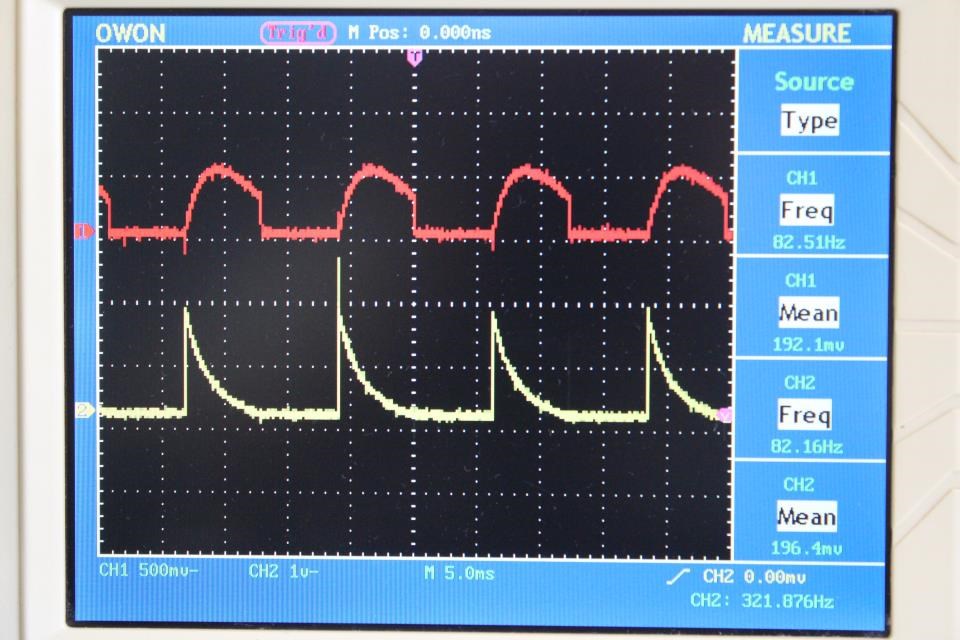
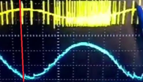
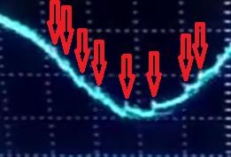
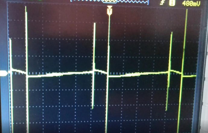
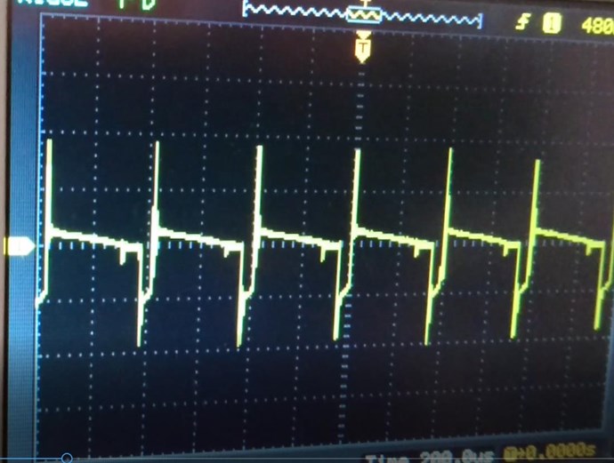
The waveform of a Triac can be tuned, or adjusted to look something like this:
Ironically, Floyd Sweet made use of a Triac, in his hoaxed Magnet Conditioning demonstration.
Note: A Triac is switched using Voltage. It is not a Current detecting device. So depending on ones configuration and if there exists a large Phase Angle difference between Voltage and Current, this may not be the best case method.
Most circuits are designed for a Mains Frequency and Voltage, so, some work to get the Frequency and Voltage you are working at may be required.
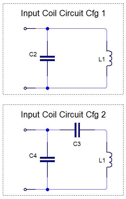
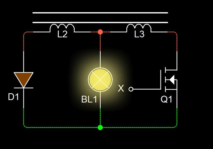
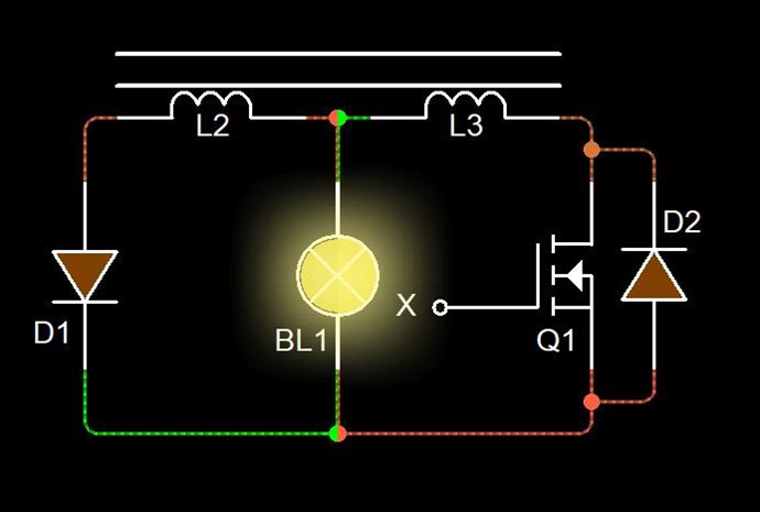
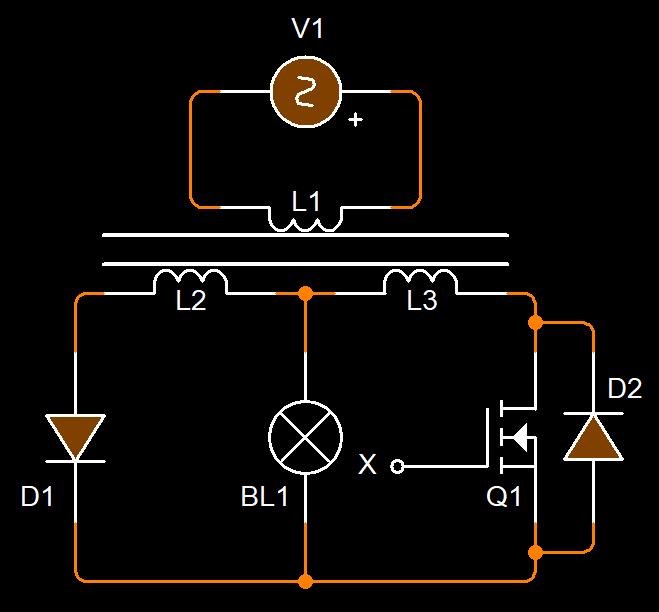
Many circuits exist, and many circuits can be employed, but the basic Voltage detection circuit is as follows:
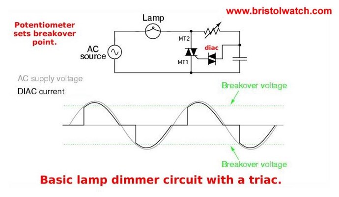
Again, do not limit yourself to a specific circuit. However, your goal should be:
- Resistive Load to ensure Voltage and Current are in phase best as possible.
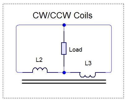
- One Partnered Output Coil must not be Conductive during the Electric part of the cycle.
- The effective Isolation of the Input to Output is effective during the Magnetic Part of the cycle.
- Learning what the difference in Conduction during part of the Cycle does: Bucking Magnetic Fields.
Remember, I said:
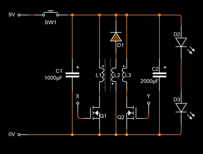
Circuitry can also be employed to delay Conduction on the second Partnered Output Coil.
Some work, some extremely simple understanding of the most basic fundamental things can be achieved by focusing on one thing:
- Bring your Machine to life - Let the Machine do what Nature wants it to do!
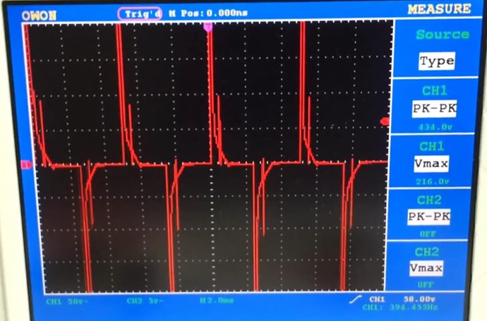
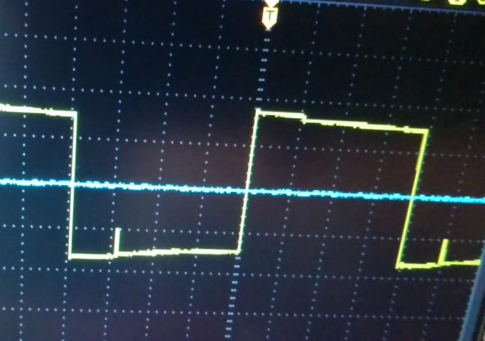
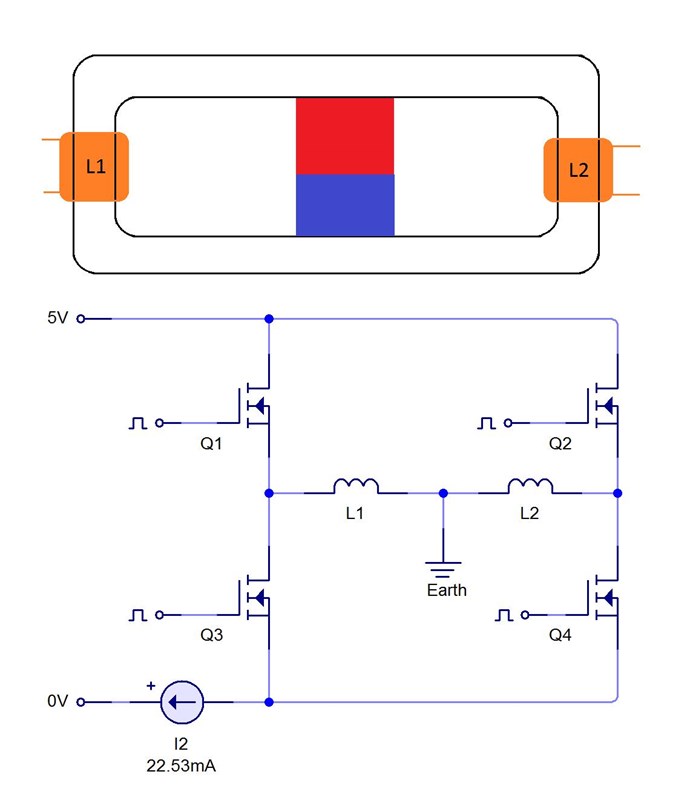
Let it be that the Partnered Output Coils Pump each other! Using Timing to achieve a specific state! Invoke Parametric Excitations of Electric Oscillations. Note, when the Magnetic Fields slap together, we also see an Impulse Pressure Wave! At this point we see a Standing Wave!
Remember what Floyd Sweet said:
If the directions of the two signals are such that opposite H-fields cancel and E-fields add, an apparently steady E-field will be created. The energy density of the fields remain as calculated above, but the value of the E-field will double from E / 2 to E.
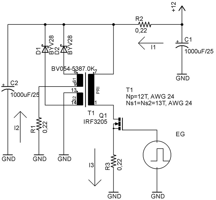
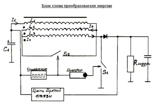
If you understand this, and all I have shared in other threads, then a simple circuit to allow your Machine to Live and Breath, will change the world today! Nature wants the Currents to Oppose, so let them, don't force the system to do something it does not want to!
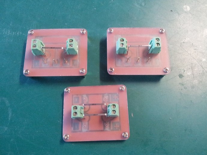
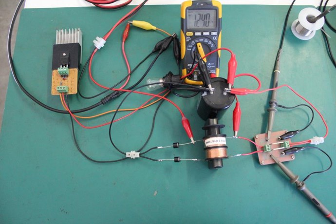
For only a few dollars and an few hours work, one could learn more in this experiment than one may realise!
Chris


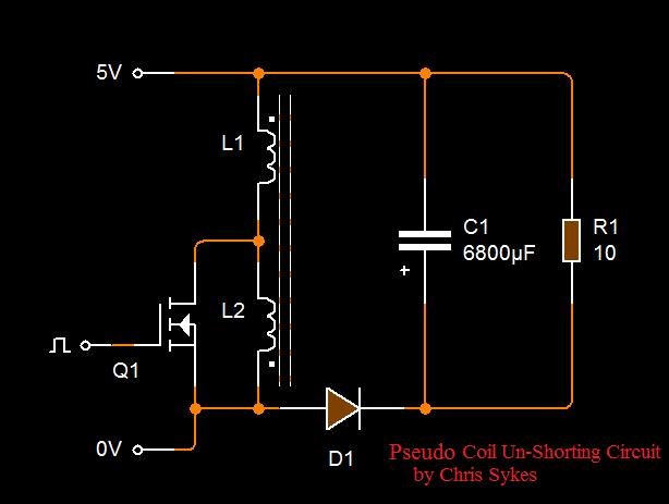




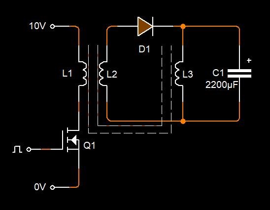

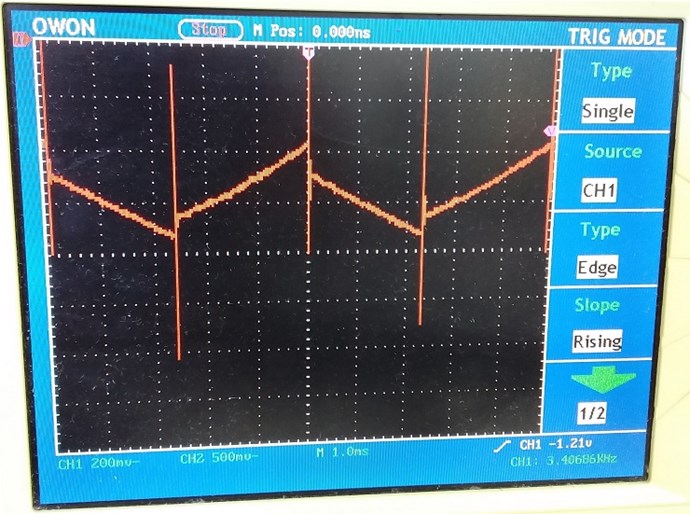
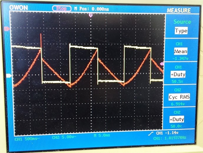
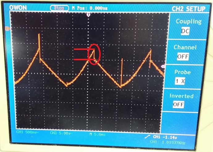



.jpg?width=690&upscale=false)
