Reliable and Flexible Switching System

  • Topic Is Sticky
  • 9.7K Views
  • Last Post 21 February 2024
Chris posted this 30 September 2017

A Reliable and Flexible Switching System is second to none, it is the most important piece of Hardware one could have on your bench!

I was lucky enough to share some data with a friend that had worked on this same concept with one of his friends, Back then, the idea was called the: Quadratron


Funny enough TheOldScientist has done some videos on this:


I have also build a few versions of my own inception of the: Quadratron which is now called IPC-quadra


Version One:


Version Two:


I have another H Bridge I use also, this is not related to the Quadratron. It is a Custom Built, Salvaged from an Old UPS, 3000VA:


I think it is important to not, this is very handy, but its not a necessity, cheaper and easier options exist. EBay has some good options. Variable Frequency and Duty Cycle are the absolute most important.

High Voltage and Current is not necessary.

I personally find a Microcontroller is a good cheap option! Easy to use, Plug and Play if you don't mind the pun! I have built all my own software:


I think if we combined our skills, we as a team could come up with a community based project that is better and cheaper than all options presented!

China could do cheap PCB's, We could build our own software!

We could find a cheap Microcontroller.

Let me know if you're keen to look into this!

   Chris 

Order By: Standard | Newest | Votes
Chris posted this 03 December 2019

My Friends,

In part of my development, of PCB's and microcontroller driven PWM, I have a new version, one that is still in its very early stages but is a lot different from my board above, again displayed here:


My new version, here:


NOTE: This board is still in Development Stage, no warranty's or guarantees can be given. Already I have made a few very minor changes for the next version of the board.

ALSO NOTE: This new PCB is based on the above Circuit, shown again here:


You will see, there are some significant changes:

  • Protect the Gate from Bounce, from the negative Rail.
  • Separated Power for each Channel
  • and a few other things.


I have three PCB's to give away.

The three people I have chosen for sharing their work are:


For those out there, if they want to sponsor this endeavour, I can put your logo on the board. Contact me via PM and we can work something out.

   Chris


P.S: The MCP1403, is no longer stocked at element14, a chip with the same Pin Out and characteristics will need to be sourced, or another supplier will need to be found. I managed to find some at Mouser Electronics. The opposite is true for the IL610. The RK-0515S is easy to find still. Be careful of the layout, don't purchase until you have checked the sizes. I am sorry, I don't have enough to share.


Single Channel list, x4 to get 4 Channel:


Of course I have also put a large Diode across the Drain Source of the Mosfet, just use whats suitable. High Current at a decent Voltage.

NOTE: At all other Readers, if you would like to purchase a Board to build yourself, please let me know. I must let you know, the components are not cheap, there is some investment in these boards.

Vidura's PWM Board might be a good option for Signal Source, where G = Ground and P = PWM Source or Signal Source.

Chris posted this 15 December 2019

My Friends,

I have been asked whats the purpose of some of the Caps. Its easier to show you:


This guy does excellent videos!

   Chris

Chris posted this 26 October 2020

My Friends,

Australia Post is not reliable enough or cheap enough for me to continue selling PCB's.


At your own risk, no responsibility on me:

I have decided to post the zip file of the gerber and drill files.


What you will need to know:

Dimensions: 126mm x 122mm

File: .gb0 -  Board outline layer

File: .gb1 -  Bottom copper (solder side) layer

File: .gb2 - Top copper (component side) layer

File: .gb3 - Bottom (solder side) solder mask layer

File: .gb4 - Top (component side) solder mask layer

File: .gb5 - Silk screen (component outline) layer


I have used JLCPCB and they are great, just upload the zip file and add the above into the instructions. They need to know what each file is for. Beware the cost, $2 PCB is not what you get because of the size and shipping.

This is given freely, but I take no responsibility from here what you or others do with it. Design V.3.0 is now Public Domain.

Best wishes, stay safe and well,

   Chris

Attached Files

Captainloz posted this 05 January 2020

Got it done! Not as clean as your's Chris, but it turned out okay.  I need to put some insulators between the Mosfets and heat sinks but if I'm carful I can use it "as is".   All that's left to do now is test it. Hopefully very soon!


Chris posted this 10 January 2020

My Friends,

After some messing around, and 20 minutes of Run Time for the Calibration, I am getting much better results:


NOTE: Don't calibrate your equipment when they are cold! It makes for terrible results! You need to run your machines for at least 20 minutes before Calibrating your machines!

An Average of 5.15 Watts on Scope and on PSU, but notice the Voltage and Current are a little off even though we get the same Output power.

  1. Voltage: 5.00 compared to 5.10
  2. Current: 1.03 compared to 1.02


Isn't this just crazy!

I hope this helps others!

   Chris

Chris posted this 10 January 2020

Hey Atti,

We are careful, we take care, error is small and we have shown a thorough approach. Not that we need it, when we reach a  level of understanding, the Output is way over the average margin of Error!

After all, if error is ±10%, but we see an Energy Gain of 200% then 10% is very small in the scheme of things!

Truly, worrying about this when the Gain Margin is so large, is a mute argument. So no need to worry, we are doing the utmost to show Accuracy, and also How to Calibrate, and check ones equipment.

Don't focus on the numbers yet, focus on the Effects and the Numbers will follow! Increase the Effects then you will see the Numbers increase accordingly!

Its not hard, ask others here replicating the Effects!

   Chris

Chris posted this 06 December 2019

My Friends,

After some work, I think we may be able to change R5 to a 680R resistor:


Something to keep in mind.

Also, for those hat have been sent Free PCB's, you will need to run a 1mm drill bit through the holes for the 5 Volt Regulator.


This is the best version of the Reliable and Flexible Switching System to date!

Enjoy my friends!

   Chris

Jagau posted this 01 January 2020

Hello my friends.

The 4 channels PWM board is progressing very well, it needs to order the IL610 isolator, I found it at an external distributor (finally).

I can't wait to see how he behaves.

In the meantime, a big thank you Chris for making me discover this forum which is really for my expectations and different from what I knew.


best wishes


jagau

Chris posted this 02 January 2020

Hey Guys and Gals,

Just a reminder, it might be wise, to change R5 to a 680 ohm Resistor.

The PCB works fine, but just gets a bit warm on the 5V Regulators. I think a 680R Resistor will reduce the heat and also allow for good performance still.

Its easy to change anyway!

I have made some changes to the next version already, the board is a bit smaller, more compact, and also traces are top and bottom for higher Current capabilities on the Main Drive Mosefts.

So, practice your un-soldering, as in some months I may have another PCB ready.

This version is by far the best PCB Version to date, very nice smooth and fast, huge bandwidth, a very: Reliable and Flexible Switching System!

Have fun guys!

   Chris

Chris posted this 22 January 2020

Hey CD,

You will be fine to use something close.

C3 16pf is a Filter Cap, to try to filter out anything that is not desirable. At least this is my understanding. Jagau can likely explain better the use here for this cap.

The value is not all that important, just use something that is close.

I cant wait to see all your builds!

   Chris

Vidura posted this 05 March 2020

Hey Andrew and welcome. There are options to buy PWM units of the shelf, most important is frequency and duty cycle adjustment. I personally prefer the analogue version, and if the on time can be adjusted independent from the frequency is helpful in many experiments. For Switch and driver you can make yourself a simple setup, for low side switching. Feel free to copy designs from the thread "developing a modular switching tool for research", Or contact me if you need assistance. Vidura.

Forushani posted this 15 January 2021

Hi


I would be glad to shoot a video for you. I built 3 boards originally, pictures above thinking my boards were not working because I did not understand how the boards were suppose to work.


Last couple of days, I decided to build yet a 4th one because I think I am better at soldering now that I have some experience and I can make it look better than before. I also had some problems while testing the boards on different coils. I think I either put too much power through them or my guess (back emf) got to my MOSFETs or something. 


The board is almost finished but it is almost 5AM and my 70 years old eyes are quitting


I am posting a picture and hopefully tomorrow I CAN DO THE VIDEO. 

It really is simple. You feed power through there Front-Right corner and the other 4 front connections are signal from the SG. One for each channel. Right now, I am using one channel.

On the back you feed the negative side of your power supply to the connector and from the other side you connect like Chris showed above.

On this last board, I am using a BNC connector. Hopefully it would work. I like that better because it makes it easier and cleaner to connect to my SG.


Where are you located?

Have you built your board yet?

I have some extra PCB boards(empty) because I ordered 10 from China and I don't think I need more than these 4 I built. Already got a bunch of money into these boards. If you have not built your board or someone else needs a board, I can ship it (From USA) at no charge for the board with you paying just the shipping.


Good luck. I hope I gave you the correct info as I am a novice myself.


Chris posted this 07 February 2023

Hey Guys,

I want to make this perfectly clear to the Community, the same Community that is trying to discredit this Circuit, the small few, that this Circuit was designed by Aero Space Engineers, with a combined experience of more than 30 Years.

Its been tested by many! Including Myself for many years!


The only problems that anyone may have, is installing inferior parts or components that are not correct.

This is truly the best Circuit any Serious Researcher can have in their Toolkit!

Best Wishes,

   Chris

Kritischer posted this 19 May 2023

Thank you @ISLab for clarifying the file format issue and summarizing the component naming issue. I've got boards on order and will take my time to assemble and test.

I've been wanting to post my build and issues but I know that comments will reflect what has been said time and time again to others.

I'm convinced that my troubles are for lack of proper switching isolation. I've taken several breaks from my build since 2019 because I can't seem to get it right even with all the parts I've accumulated. I don't know why it's been so difficult for me. It might be analysis paralysis with there seemingly being so many options for a circuit. It might be that I'm afraid to succeed or don't feel like I deserve to. Ether way I just want a switching circuit and I'll do anything at this point. Thank you for doing what you do.


Chris posted this 01 October 2017

For those that are not in the know, a System like this, a Custom, or a Reliable and Flexible Switching System, will allow you to set a Frequency and a Duty Cycle easily and quickly!

The Microcontroller: 


All controlled from your computer or laptop:


Or:


All done very easily, a GUI that can be easily customised! Simply scroll your Mouse Wheel and the Frequency or Duty Cycle is changed.

Alas, no good for cooking Sausages!

   Chris

Zanzal posted this 04 October 2017

Were you considering a DIY kit, or a retail item to be sold, or a how-to instructable for people to build their own? I'm all for using knowledge to build useful and exciting products. 

If you are looking for ideas: a tiny OLED screen, a few rotary encoders, and an ESP-32S would be a fairly cheap way to go. Simplify the circuitry by using opto-mosfet drivers (FOD3180 for example). The wifi on the ESP-32S means that a web interface could be added with one of the two cores for signal generation. Add a 3D printed case and a 5V wall adapter.

Captainloz posted this 03 January 2020

Thanks Chris, Yes I keep blowing stuff up!  So these make things a lot quicker to replace.

Here is the Ebay links for people that are interested in the Mosfet and Regulator sockets.

https://www.ebay.com/itm/US-Stock-10Set-2EDG-3-Pin-3P-Plug-in-Screw-Terminal-Block-Connector-5-08mm-Pitch/371874798270?ssPageName=STRK%3AMEBIDX%3AIT&_trksid=p2057872.m2749.l2649

https://www.ebay.com/itm/10Pcs-2-54mm-0-1-Universal-3-Pin-3-Poles-PCB-Screw-Terminal-Block-Connector/293045917624?ssPageName=STRK%3AMEBIDX%3AIT&_trksid=p2057872.m2749.l2649

The only issue with these is you increase the distance between the components, so it's possible to get some ringing, I guess... 

These are for the inputs-

https://www.ebay.com/itm/10Pcs-2-54mm-0-1-Universal-2-Pin-2-Poles-PCB-Screw-Terminal-Block-Connector/293251391717?ssPageName=STRK%3AMEBIDX%3AIT&_trksid=p2057872.m2749.l2649

Loz


Jagau posted this 05 January 2020

Hello friends, just arriving from a 4 days trip, I have to update myself.

Nice job Capt loz

Ok for resistance R5 Chris. Thanks


Jagau

Chris posted this 06 January 2020

Hey Loz,

Currently I am using a 12V DC Transformer.


Maybe check for a bad Zener Diode? Perhaps one of them is bad? The 5V ones by the IL610 IC? Not sure what else might be the problem. I have also had heating problems, and I think we can improve this. Maybe try a 1K resistor instead of a 680R?

I will also do some more investigating.

   Chris

Atti posted this 10 January 2020

The Rigol DS 1052 gives you half an hour warm-up time before self-calibration.
So even here, there is a margin of error.

Chris posted this 21 January 2020

Hey Jagau,

It is, my friend, AR on the original Circuit, gave me the circuit, I made a few small changed, but it is the best I have ever seen when it comes to Isolation and Speed and Bandwidth.

Some of my earlier Circuits had some small mistakes / Imperfections, but this last version is by far the best I have built!

I have already started a new version, it has a few improvements, Double sided on some High Current Traces, shorter Traces where possible, moved the Decoupling caps closer to the IC's, better size, a little smaller, and little better cutout, around the outside:


I really enjoy prototyping stuff like this, not sure if much more improvements can be made here on in.

   Chris

Jagau posted this 30 January 2020

I apologize I had not seen your question, I hope it is not too late.
As said the manufacturer and I quote:


  For high-speed logic signals (tr, tf <10 ns), a 16 pF capacitor is recommended. But the capacitor value is generally not critical; if in doubt, choose a higher value.


I personally use a 20 nf

Sorry for the delay


Jagau

Jagau posted this 25 February 2020

Hi chris


I started to experiment with the card I received. As you can see on the scope shot, the insulation is excellent, even better than I thought. No distortion on the input signall on channel 1,  compared to the output signal channel 2, excellent.


Regulation with a minimum input voltage of 7.5 volts, this is what the 7805 needs to regulate well, is perfect,  which gives me a very precise 5 volts even with the lamp on


thank you again many other projects in mind with this card.


Jagau

Chris posted this 25 February 2020

Hey Jagau,

Thats excellent! I am very pleased to hear youre so happy with the PCB.

It is one of the best Circuits I have ever used! By far! It is very precise and very reliable. Of course the components installed, Mosfet and so on does make a difference also, but the general circuit is first class!

I am so pleased to hear! Thank You for letting me know!

Best wishes,

Chris

Andrew posted this 05 March 2020

For those of us without the necessaries (ability, time, space) to build such a thing of wonder, would an off-the-shelf variable frequency drive/inverter be suitable for pulsing the primary coil? Or is there something else you'd recommend? I'd like to build my own when the time is right, but I'm itching to start experimenting asap...

Chris posted this 19 April 2020

My Friends,

It is early days, not much testing has been done, but V3.0 of the 4 Channel Isolated Mosfet Driver Board is on E Bay.


Note: This is a PCB Only.


The MCP1403, is no longer stocked at element14, a chip with the same Pin Out and characteristics will need to be sourced, or another supplier will need to be found. I managed to find some at Mouser Electronics. The opposite is true for the IL610. The RK-0515S is easy to find still. Be careful of the layout, don't purchase until you have checked the sizes. I am sorry, I don't have enough to share.


Single Channel list, x4 to get 4 Channel:


Version 2.0 I have tested thoroughly, version 3.0 has not been tested so much. These PCB's once assembled and working properly, are worth their weight in Gold! See the above testimony's!

Anyone not having an Electronics background, I do not recommend purchasing, these are fairly involved to put together!

For beginners, I would recommend purchasing Vidura's Switching Module, Vidura's units are ideal for those that do not have a great Electronics Background. Please contact Vidura for more help.

   Chris

Jagau posted this 26 October 2020

Hello Chris

You have a lot of compassion and a big heart my friend.

I think it will help a lot of people who haven't had the chance to have it, it is a real gift.


Thank you


Jagau

Chris posted this 26 October 2020

Hey Jagau,

Thank You My Friend!

We have nothing, if we don't have each other. I want the Human Race to succeed with all my heart!

Best wishes, stay safe and well,

   Chris


Chris posted this 04 November 2020

My Friends,

NOTE: I do not consider Itsu a Troll or a Trouble maker! He posts with Trolls and Trouble Makers. Itsu is a hard worker and does excellent work. I do not consider Verpies a Troll or a Trouble Maker either.

Some news:

Ref: Captainloz Video 9 (showing COP = 2) replication


They will be doing one of two things here:

  1. Genuinely building the RFSS and testing it, and attempting to use if for their experiments. To benefit from.
  2. Building it to try their very hardest to find a fault that they can use to explain where all our Success comes from. Let them Try! We know better!


Note To Itsu: If you Succeed, I would not go public on the Forum you currently post! You will see what you think of as your friends, turn against you, attack you and make you feel less than 1 inch tall! They will Troll you like you have perhaps not seen before! So, a friendly Warning, be very careful what you say and where you say it if you don't want Trouble from you so called Friends!

It is very hard to trust the Haters, the ones we have had so much problems from in the past!

Best wishes,

   Chris


P.S: The IL610 is not an Optocoupler, it is Giant Magnetoresistive (GMR) technology, or you could say a magnetocoupler. Not an Optocoupler! The difference is about 50MHz!

Forushani posted this 14 January 2021

Thanks Chris. What I meant was just label. You are the true MASTER


Chris posted this 13 January 2023

Hello ISLab,

Your questions:

Hi @Chris, does this work with High Side operation also? Or does it need to be modified with bootstrap circuit for that?


Yes, no, not sure how familiar with Electronics you are, but any Isolated driver will work Low side and also High Side. This circuit is fully isolated, as you can see by studding the Circuit, and High Speed!


Also, you gave links for PWM circuits here:

Don't forget, we have projects for Input PWM also:

Several of these threads are missing.


Yeah, some disgruntled Ex-Members have gone through and deleted their threads. It does not matter, because they are not needed and really are 99.9% irrelevant because this thread overrides the ones that have been deleted. This was done before the Delete button had the timeout implemented.

In retrospect what would you recommend as PWM for long-term work?


Of course, any serious Researcher and Experimenter needs a Toolkit that is relevant for the work that they are doing, so its a decision that only you can make, not one for anyone else to make!

Best Wishes,

   Chris

ISLab posted this 09 February 2023

Thank you Chris! This is a very valuable gift from you to the entire Over-Unity researchers community -- one more among so many others!

I wish someone on this forum had told me right at the beginning to start by building this instead of making simple but limited circuits to experiment with.


So let me do my part here:

To all those on this forum who are serious about long-term research and experimentation, please make this device your base for switching system, even if initially this requires additional expense and time to build. You will save yourself many hours (or rather many months!) of avoidable problems and inconveniences.

You absolutely need a fully isolated system and, depending on your line of experimentation, may need anything from one to four of them.

I've made mine recently and I really wish I had started with this from the beginning! 😊


Tips for the new builder

I'm also sharing a few points that will be helpful for the new builder, based on my recent experience in building this.

  • Take the latest Gerber files as shared by Chris above. But these will no more work as they are on new Gerber viewers or PCB makers, since the Gerber files definitions were revised since that version of the software used to make these was released. In particular, the header code as present in these files is now obsolete. The KiCad Gerber viewer gives error message:

Invalid GERBER format command 'D' at line 2: "%FSDAX23Y23*%"

You can ignore this normally. But if you want to remove the error, then edit the first line (as above) and replace "D" by "L", so that the line becomes: "%FSLAX23Y23*%".

  • Most current PCB makers require the file names extensions to follow the new naming convention: TOP.GTL, BOTTOM.GBL, TOPMASK.GTS, BOTTOMMASK.GBS, TOPSILK.GTO, BOTTOMSILK.GBO, DRILL.DRL, where the extension must correspond to the kind of content in the file, but the file names can all be the same. So:

With these two corrections you will have no problems viewing or uploading for PCB manufacture.

When you place the components, note that the screen markings (on the version 3 boards) have two mistakes:

  • The markings of D2 and D3 are interchanged in all four channels
  • The first Diodes incoming from the PSU are marked D1, D2, D3, D4 respectively on the four channels, when they should have been the same D1 or D6 as in the parts list, or D11 as in the circuit diagram.
  • D5 is wrongly named both in the circuit diagram and in the parts list, and should actually be: 1N4733 (5V1 Zener)

As Chris said, when in doubt, follow the circuit diagram.


I hope these notes help you and save you some avoidable struggles.

Chris posted this 20 May 2023

Hey Kritischer,

We are here for you Mate! I will do the best I can to help where I can, but yes, I agree, to a degree, there must be a frame of mind gained, to be able to move into a new world!

The Power to become Self Sufficient, in so many ways, it is each and everyone of ours, and the path forward is one we can only take by Choice. 

We are here for you mate!

I posted this thread many years ago to give you all the step forward, that took me so long to achieve, because a good reliable Switching System is a very difficult task to achieve unless one has a very good EE Knowledge.

Best Wishes, and good to know you're still here with us!

   Chris

Kritischer posted this 27 May 2023

I'm not able to add images to this post. I disabled ad blockers etc and use Brave Broweser.

I'll try later but I just spent a while typing this up and I need to get out of here.

I used

MUR8100E for the UF Diodes

C3M0065090D for the power mosfet

I'm showing my coils here but any specific measurements would naturally go in a dedicated post.

I'm powering the board with a 12V 1A wall brick. I have a bench pulse generator on the left of the Denon.

I do see 15.4V or so on pin 6 of the MCP1403. The PWM signal can vary to +10V max.

I triple checked the direction of all the diodes but another set of eyes wouldn't do any harm.

It got late as I started looking at signals and I'm having a hard time watching the Gate.

I followed it back to pin 5 of the MCP but I'm not seeing a clean signal.

I'm even having a hard time seeing the signal on pin 6 of the IL610.

I'm sending in a 1khz signal 10% to start. 

I connected the + output of the mosfet to the + of the PSU. The - of the PSU goes to the + of the primary coil. The output of the primary coil returns to the gnd/source. I only put 1V in.

Maybe all the isolation makes it tricky to probe, but admittedly I did just get this scope and I'm getting used to it. I can see the calibration signal no problem. I can see the PWM input from the generator no problem. Everything inside the circuit I'm having issues seeing. 

I'm going to get some sleep and get back to this when I can. Realistically it will be days. I felt good about following the diagram once I had boards in hand, and it went together nice on a hot plate to preheat for hand soldering. Even so something must be wrong. I'm going to spend some time on the mosfet datasheet. I bought those a while ago and wanted to see if they would work here. Besides that I'm out of things to try.

Hopefully after some rest and a better understanding of where the test points are I'll make some progress.

Thank you for doing what you do.


Kritischer posted this 03 June 2023

Stupid question, but, Kritischer, you have checked the Input Signal is 5V from the Zero Graticule Line to Peak and not 5.5V from Peak to Peak?

Of course, this will be an issue if you have made this mistake, it needs 5V Input Signal, not 2.5V Positive and 2.5V Negative, not Negative Going Signals, not AC Signals.


 I switched from a 12VDC supply to one labeled 7.5VDC per recommendation. I don't know how that could happen.

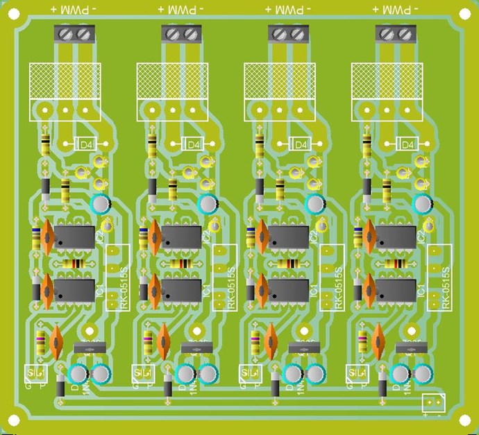
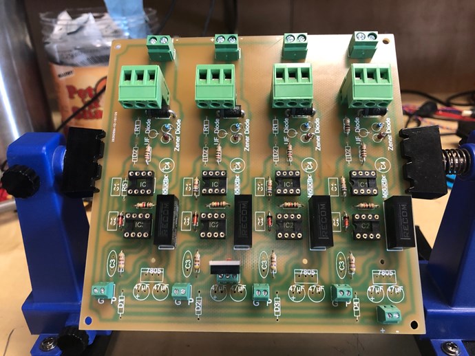
This is a very simple circuit and I have not seen anyone have such trouble with it, normally it is an easy build and its just works, 100% Solid and Reliable!

I tried to explain that I struggle. Even so, I have done other things that I feel have been more difficult. This is painful.

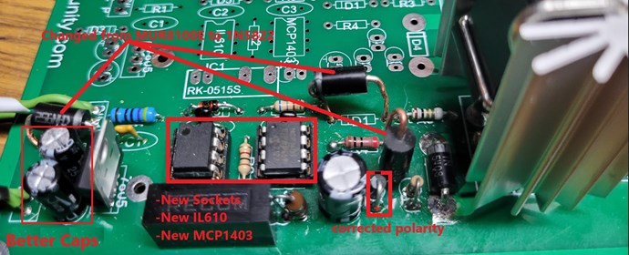
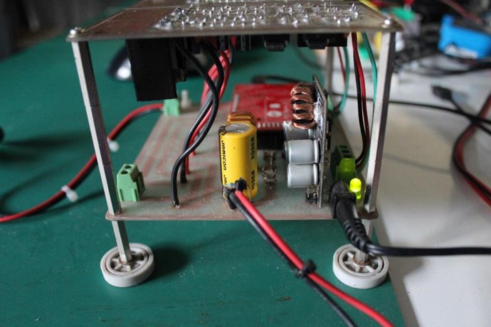
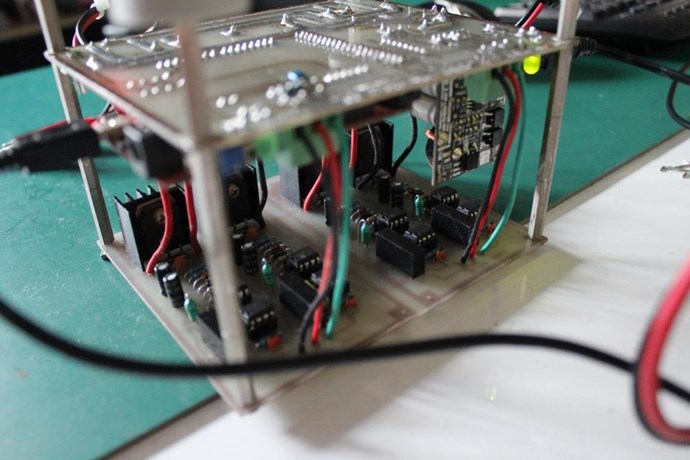
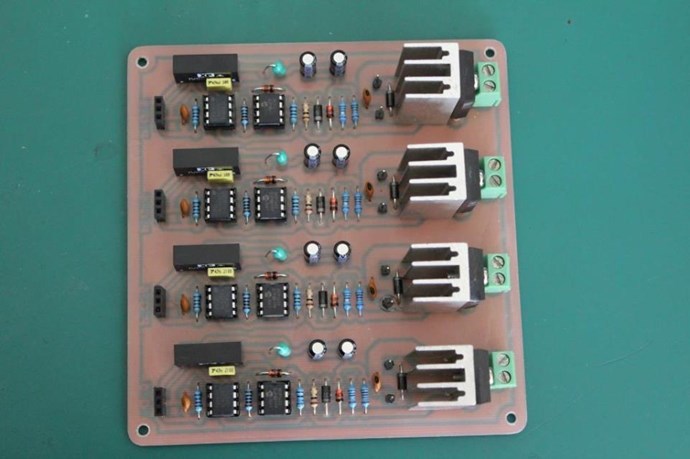
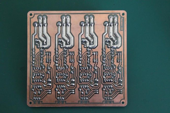
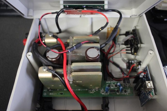
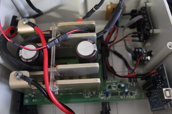
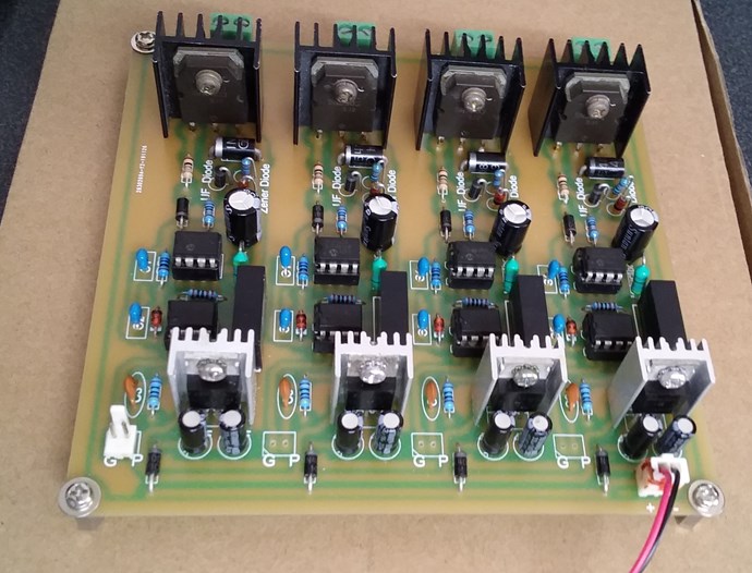
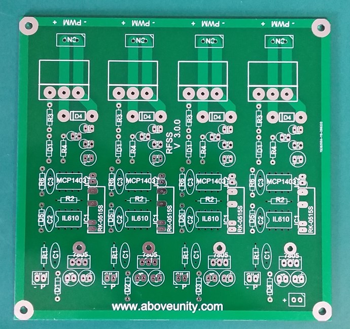
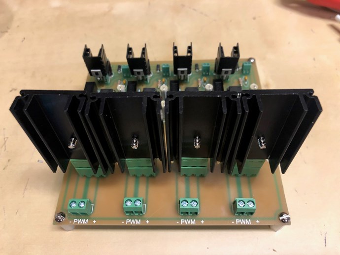
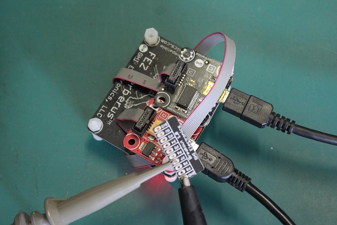
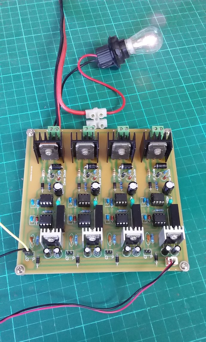
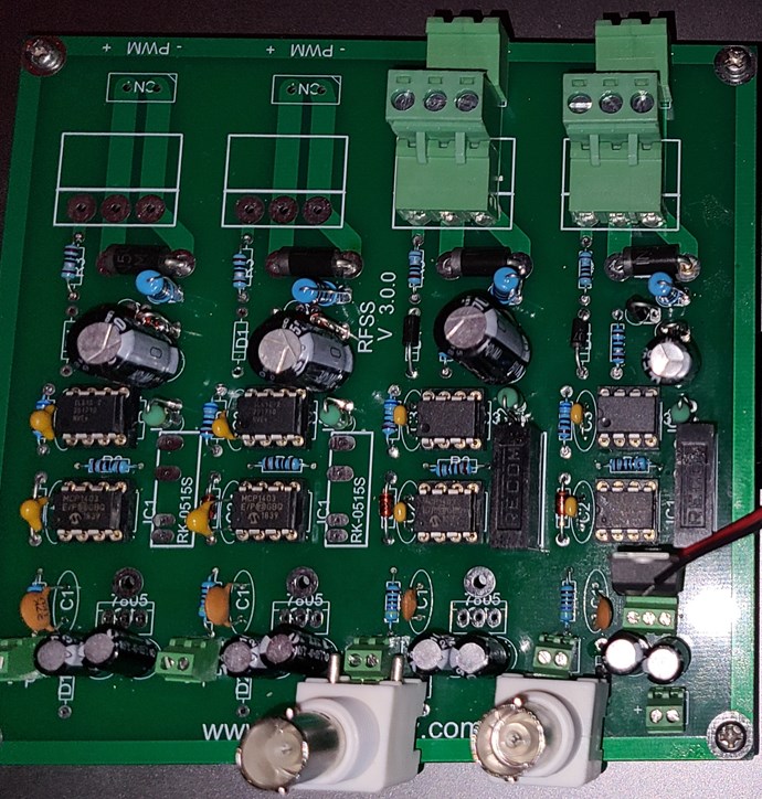
This summarizes the changes to the board. Sorry for the text.

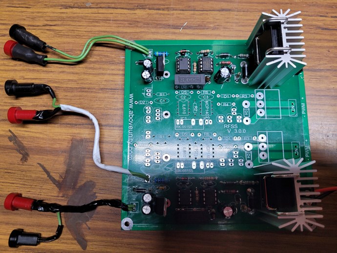
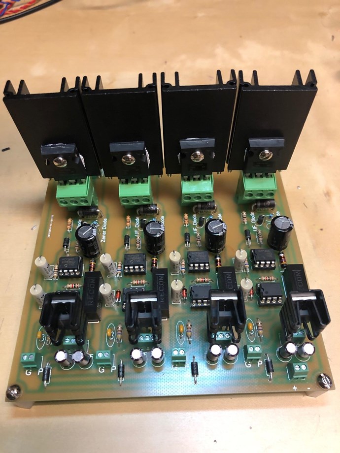
Last night I replaced both sockets and installed new chips, and replaced the 100uF caps.

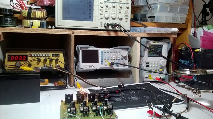
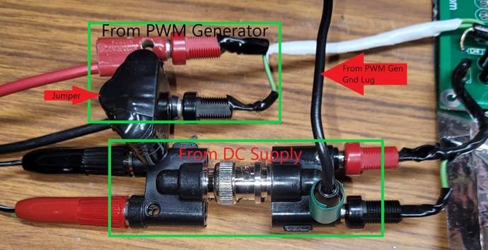
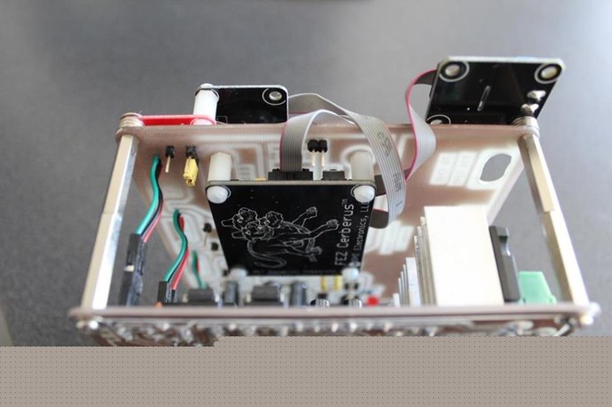
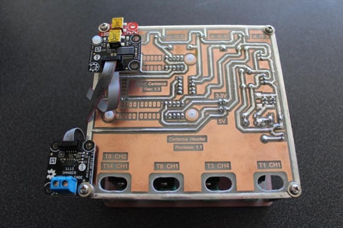
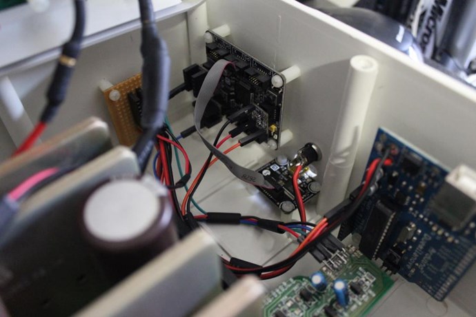
I started getting paranoid about the Signal generator Negative with respect to the Gnd lug on the back vs the DC supply so I put this together so I could jump in or jump out the Gnd.

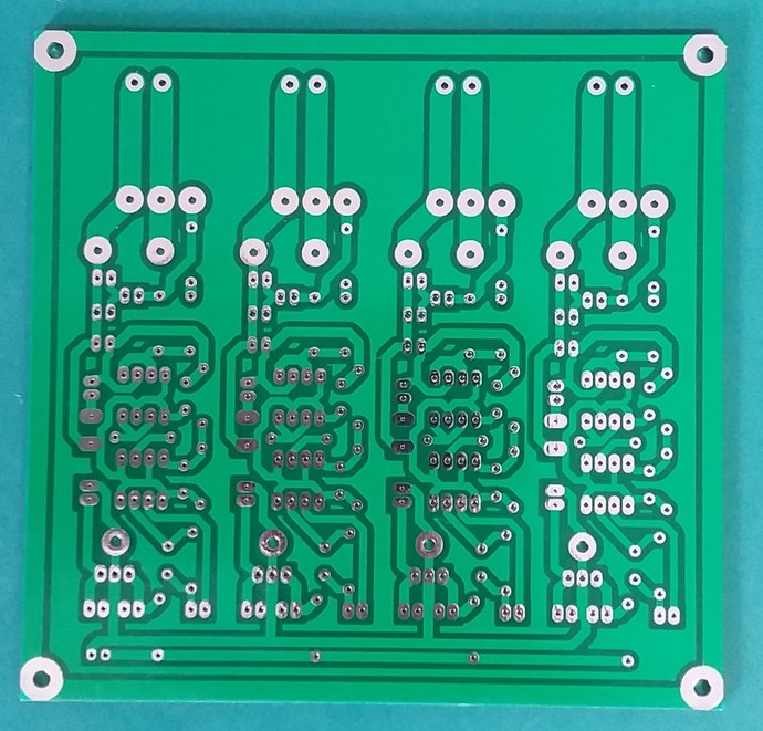
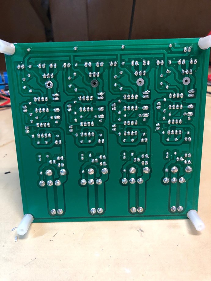
I verified continuity of everything seen.
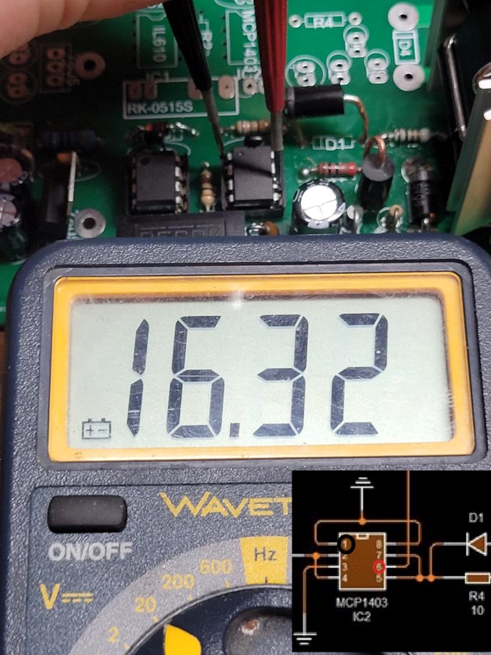
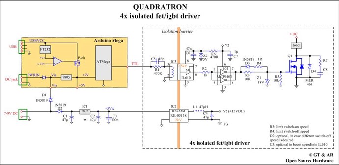
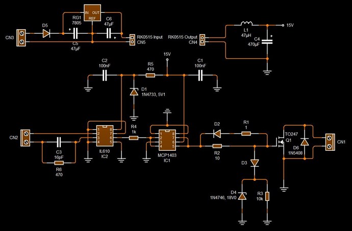
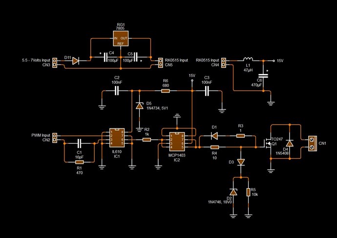
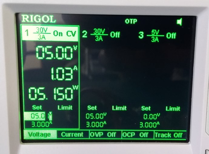
 

IL610 Voltage


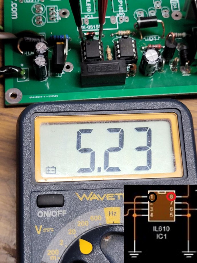
The MCP has power, but I don't know why it's over 16V with the 7.5V supply (if it's even related) It  used to be ~15.5V when I was using the 12V supply, but then again I did make the grounds common. I don't know.


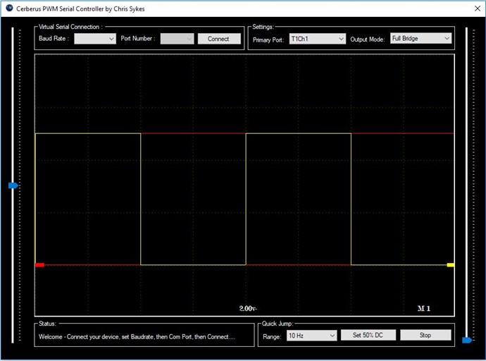
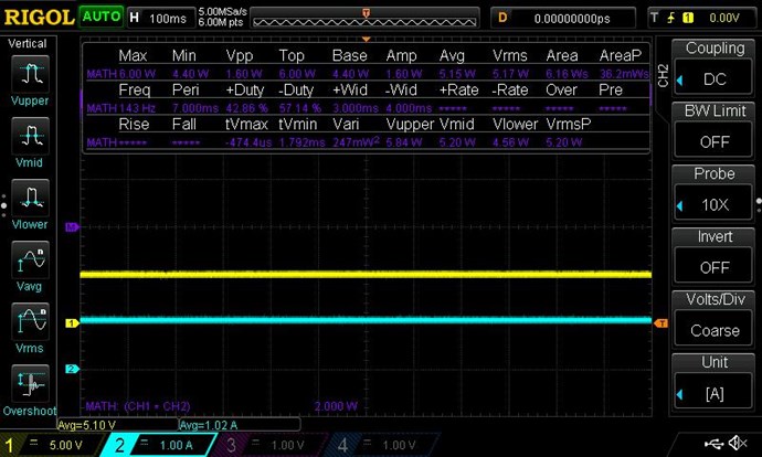
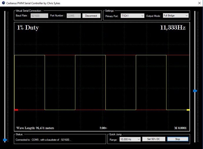
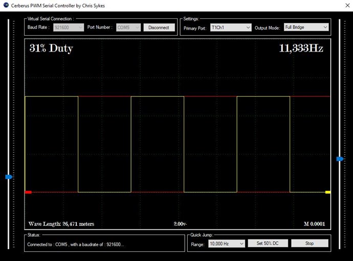
There is signal on the IL610 input


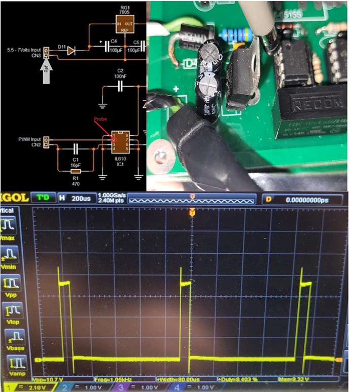
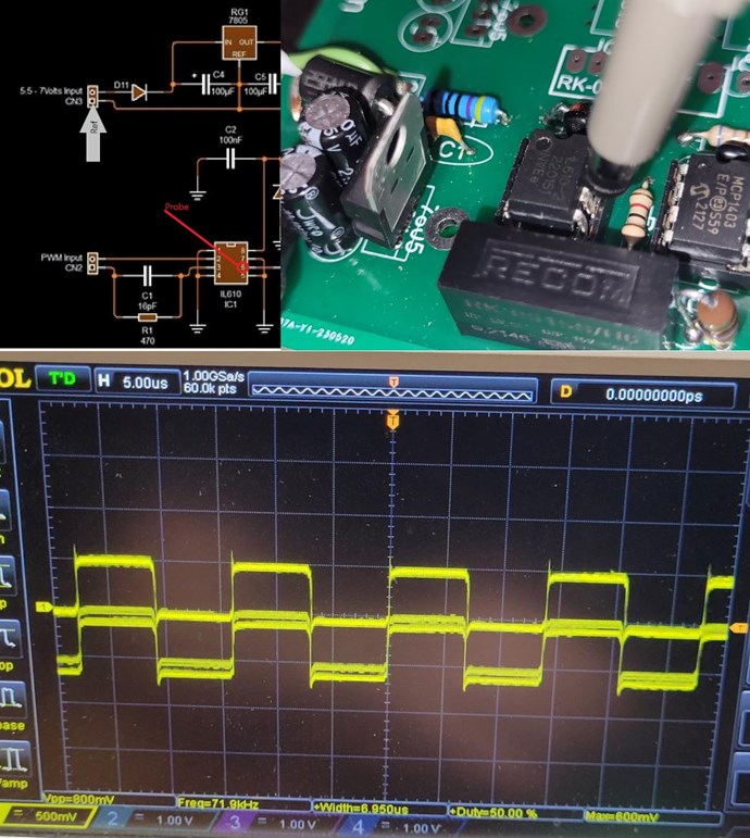
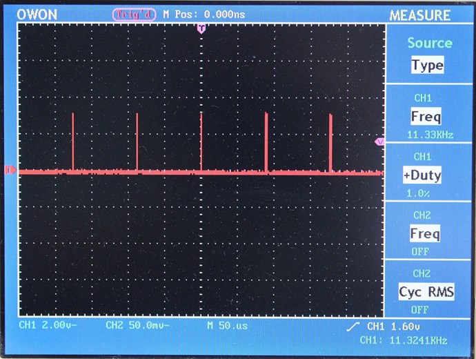
But when I probe the output and hit Auto I don't see anything resembling the input signal.

I tried using the reference shown, but I also tried using pins 1/4/7/5 and they all look like this

The input signal hasn't changed from 1Khz 8% duty at this point. I did hit auto on the scope.
The signal is low and I don't know where 71.9Khz is coming from.


Donovan had said to scope grounds anyway. 

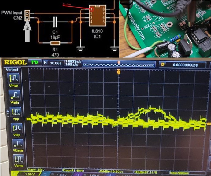
I shouldn't be seeing anything like what I'm seeing here should I?

 (One of the most important things is to keep an open mind when troubleshooting......I have had many people say things like, ground is ground, why measure it.....yes, but your troubleshooting....is it really ground, or is that the problem...)  I hope that makes sense.....we want to see if there is actually a signal present at the I/P pins..

There's a big difference between what happens in simulation and theory and what actually happens in practice. Real bench guys develop different subtle relationships with equipment and over the years develop practices that an armchair technician might scoff at. Some things might even seem superstitious. When a guy with 10k hrs on the bench suggests something it's probably worth the effort. 

I have not seen anyone have such trouble with it,

I am he. Behold!

At this point I'm just waiting to see if replacing the IN5822 with the 1N5819 does anything.

Outside of that.. the only thing I could blame besides myself is the wiring.

My house is very old and the wiring isn't great. To make it worse, I'm 25m across the property in my barn that is powered by wiring going from the main building to the barn. I don't see a separate ground rod. I have never had a problem with other electronics but this is more sensitive instrumentation. I thought it was worth mentioning.

I am assuming your scope is isolated from ground, with an isolation transformer, or a ground lift plug.

The scope is a Rigol DS1054Z that I purchased for this project. I scoured the manual for references to grounding and isolation but didn't find any. It's not safe to assume. I am not using either a separate isolation transformer nor a ground lift plug. 

If I'm not doing something right, it's because I don't know any better or it's the first time something has mattered.

To rule out my AC mains I'm going to bring over my Honda EU2000 generator and try using that.


Kritischer posted this 07 June 2023

Thank you all again tremendously for the thoughtful comments and guidance.


I have had repeated success using the 2nd (top) channel.

I changed diodes, resistors, and the RK0515 on the bottom most recently. 

Now that I know where to probe across easiest (pin 1 of IL610 and one side of 1kΩ off pin 6) the signal presence is obvious and clean. I'm now positive (or have at least convinced myself) that I damaged the other IL610's. I should probably swap the one from the top, but I hate these chinsy dip sockets and don't want to push my luck. I ordered more IL610's expedited because I need at least 2 channels this time around.

I had the setup ringing last night while trying to light a bulb as a regular transformer. I didn't get there yet but the switching definitely works and the rise times are < 20nS. I saw upwards of 140V p2p from a 4.5V input from the PS. I need to get better at taking scope shots for my next post, which may be here or somewhere else on the forum. 

Chris posted this 04 October 2017

Hi Zanzal, not sure yet.

The Circuit above is not mine to sell, so I will have to come up with something different.

A small plug and play board would be nice, easy for people to get started.

WiFi has trouble with this sort off thing, the work we are doing, there are frequencies that take out the WiFi and the device becomes unresponsive. So, although a good idea, its a bit hard to incorporate.

Yes a oled would be a good idea!

   Chris

Chris posted this 08 October 2017

Were getting off topic and should move our conversation to the Akula's 30 W lantern Thread,

Most of the Akula Circuitry is to drive the Mosfet, he uses the Term Transistor. Not Mosfet.

Which is what we are looking at here in this Thread. The optimum and easiest, flexible configuration to produce a wide range of Wave forms.

It is the Interactions in the Coils, and between the Coils that needs attention.

   Chris


Vidura posted this 20 September 2018

Related to this thread I would like to post some experiences and ideas. I have used custom made pwm generator s with microcontrollers and analogue ic, both have there advantages and drawbacks. Microcontrollers are accurate, can be clocked with crystals, and have very flexible programable adjustments and operating modes, a drawback is the limited resolution of duty cycle and frequency, and a kind of rippeling when scrolling . In contrast the analog ICs have virtually infinite resolution in frequency and duty cycle, although at the cost of less stability and flexibility. A few months ago I decided to purchase a function generator, a useful tool for electronic works, but regarding the pwm-square wave mode I am not at all convinced that it is the best solution. There might be better devices available, but the one I bought is have only one rotary encoder, so for every change of a parameter I have to change the selected mode , the decimal range etc, which is quite impractical.So I prefer the simple pwm with two variable resistors , where I can adjust frequency and duty cycle simultaneously, and sweep throu the range quickly. So I was thinking about how to unify the advantages of the microcontrollers and the analogue IC. I found some microcontrollers with NCO , a numerical controled oscillator, which have an excellent resolution and accuracy, combined with the flexibility of a programmable MC. When I have something elaborate I will post here or in the microcontroller section.

Atti posted this 04 December 2019

Hey Chris, that's a nice gesture.

thaelin posted this 04 December 2019

Hi Chris:

   Following this with great interest. I am in the make of a sig gen that was published in Radio Electronics and has some very good aspects. It doesn't have the versatility of what you are sharing here. I have sourced all of the parts except the IL 610 as well. Have you considered the use of optical isolation in this unit? I have in the past used light triggered transistors and had very good luck on the switching times. I do have an arduino staring at me and needs a job.

   What's your feel for this idea?


thay

thaelin posted this 18 December 2019

  Great news if not already known. DigiKey has 500 IL610-1E in stock right now. I am hoping that this piece will work the same. It shows as  General Purpose Digital Isolator 2500Vrms 1 Channel 100Mbps 15kV/µs CMTI 8-TSSOP, 8-MSOP (0.118", 3.00mm Width).  They are surface mount but hey, can get them now. If you buy 10, it will be about $40 plus shp.

  So Chris, it looks as if your  pulser will be a better choice than the one I want to build. It will only do 300K and that is limited on some areas. I do have an Arduino and a Pi3 to drive it.  Is the last posted schematic the current one. Will get an order out soon and go for it.

On that core, last price I saw was $384, is that right? Hope there is a better place for it.


thay


Chris posted this 31 December 2019

My Friends,

Any updates / Progress on the PCB's I sent out to people?

I would love to hear on the progress and what experiments you are using the PCB's for!

Best wishes,

   Chris

Captainloz posted this 02 January 2020

I'm making progress!  I just didn't have enough parts, but they are on the way!

Flexible Power Supply PCB

Cheers,

Loz

Chris posted this 03 January 2020

Hey Loz,

That is awesome! Some good ideas there for securing the Fets and Input Wiring!

Very Nice!

   Chris

Captainloz posted this 06 January 2020

Hi Chris,

I just tested the board and all is good. I just have a question on the input voltage for the board. If I go over 5 volts it seems to draw a lot of current.  Is it okay to keep the input voltage at 5 volts?  

Cheers,

Loz


Captainloz posted this 06 January 2020

Hi Chris,

Yes I installed the 680R resistors.  What input voltage do you use on diode D5 input CN3? 

I've been playing around with it and it's working great, I'm only inputting 5vdc on input CN3 / diode D5, nothing is getting hot. 

Cheers,

Loz

Chris posted this 09 January 2020

My Friends,

I have learnt something. Because this power supply is Constant Current Constant Voltage, we need to take into account my measurements were true Voltage and Current, which may not reflect the same values.

Constant Current Sources:


Rigol DP832 Power Supply:


I need to calibrate my DP832 Power Supply - The pdf is attached. Thank Jagau for the heads up!

Help:


Still I am not happy with the Rigol DS1104 Scope, it  is so slow! Maybe a firmware upgrade may help?

Sorry, a little off topic here, although it is hardware, just not about the: Reliable and Flexible Switching System

Best Wishes,

   Chris

Attached Files

Jagau posted this 11 January 2020

Hi chris


I just received a good part of the parts for the quadratron.
I'm still missing some back order parts but the project is progressing well.

If you don't mind I will make some modifications to adapt it to my needs


Jagau

Chris posted this 20 January 2020

Hey CD,

Yes Diodes don't need to be Ultra Fast, but on the Switching side, it will be of benefit if you can.

The faster the Diodes conduct, the faster the Diode can dump Gate Current to Ground. For Faster On and Off Times.

Input Diodes are protection diodes, stopping Current in the Reverse Direction. All Diodes are in the right direction, remembering the MCP1403 dumps gate Current to Ground Internally:

The Low Side PNP Mosfet on the Output Pin, when the signal is off, Grounds the Output Pin.

I hope this helps!

   Chris

We're Light Years Ahead!
Members Online:

No one online at the moment


What is a Scalar:

In physics, scalars are physical quantities that are unaffected by changes to a vector space basis. Scalars are often accompanied by units of measurement, as in "10 cm". Examples of scalar quantities are mass, distance, charge, volume, time, speed, and the magnitude of physical vectors in general.

You need to forget the Non-Sense that some spout with out knowing the actual Definition of the word Scalar! Some people talk absolute Bull Sh*t!

The pressure P in the formula P = pgh, pgh is a scalar that tells you the amount of this squashing force per unit area in a fluid.

A Scalar, having both direction and magnitude, can be anything! The Magnetic Field, a Charge moving, yet some Numb Nuts think it means Magic Science!

Message from God:

Hello my children. This is Yahweh, the one true Lord. You have found creation's secret. Now share it peacefully with the world.

Ref: Message from God written inside the Human Genome

God be in my head, and in my thinking.

God be in my eyes, and in my looking.

God be in my mouth, and in my speaking.

Oh, God be in my heart, and in my understanding.

Your Support:

More than anything else, your contributions to this forum are most important! We are trying to actively get all visitors involved, but we do only have a few main contributors, which are very much appreciated! If you would like to see more pages with more detailed experiments and answers, perhaps a contribution of another type maybe possible:

PayPal De-Platformed me!

They REFUSE to tell me why!

We now use Wise!

Donate
Use E-Mail: Chris at aboveunity.com

The content I am sharing is not only unique, but is changing the world as we know it! Please Support Us!

Thank You So Much!

Weeks High Earners:
The great Nikola Tesla:

Ere many generations pass, our machinery will be driven by a power obtainable at any point of the universe. This idea is not novel. Men have been led to it long ago by instinct or reason. It has been expressed in many ways, and in many places, in the history of old and new. We find it in the delightful myth of Antheus, who drives power from the earth; we find it among the subtle speculations of one of your splendid mathematicians, and in many hints and statements of thinkers of the present time. Throughout space there is energy. Is this energy static or kinetic? If static, our hopes are in vain; if kinetic - and this we know it is for certain - then it is a mere question of time when men will succeed in attaching their machinery to the very wheelwork of nature.

Experiments With Alternate Currents Of High Potential And High Frequency (February 1892).

Close