I'm grateful that you guys see fit to reply at all. Thank you again @ISLab once again for the thoughtful comments and to you @Chris for removing the image filesize cap.
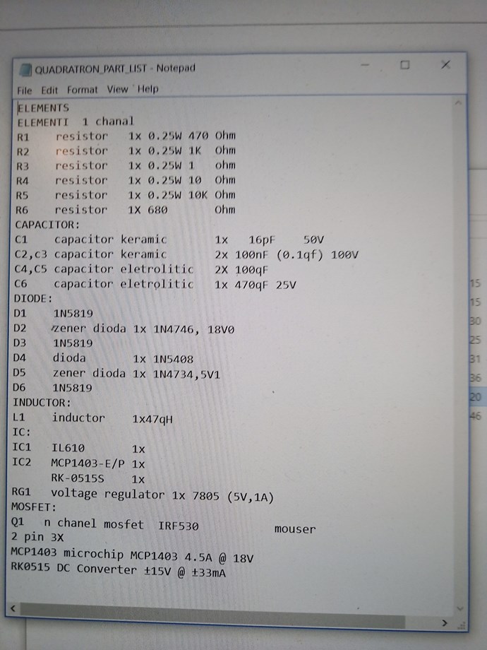
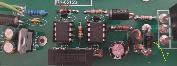
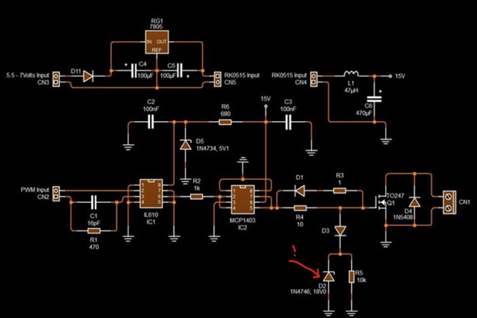
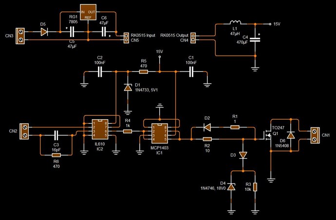
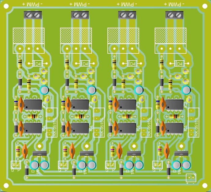
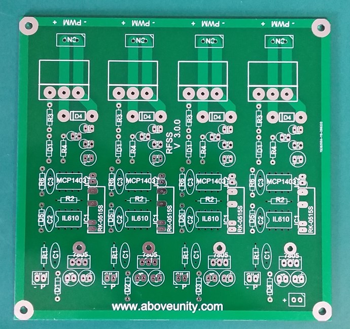
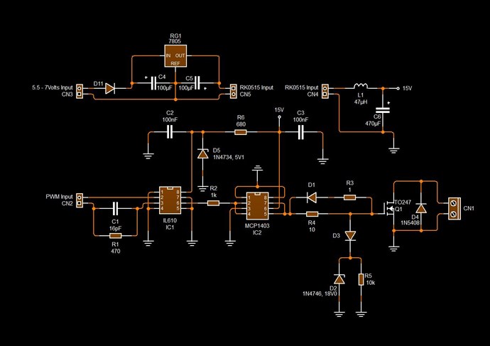
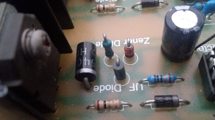
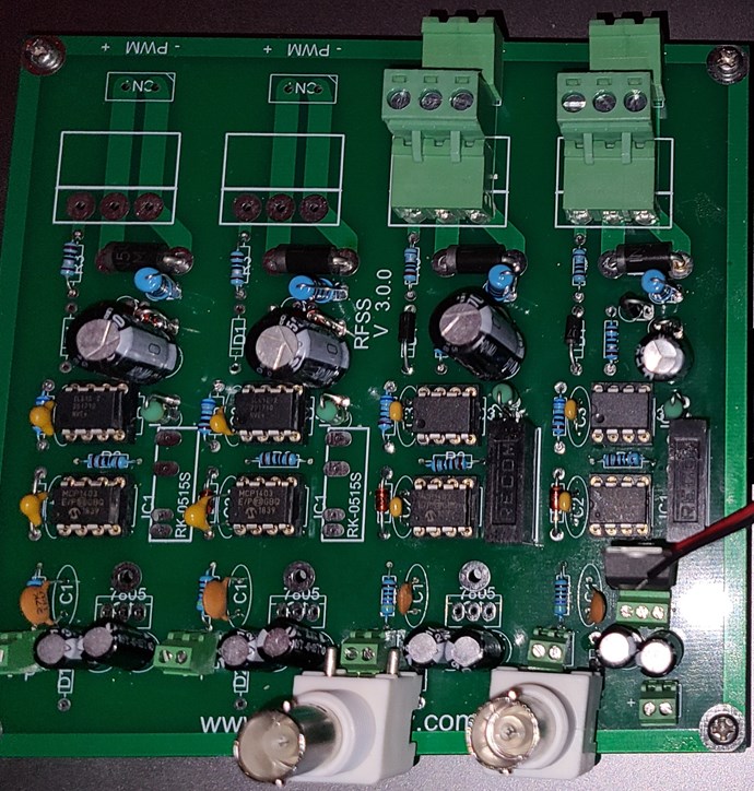
But note the correction to specs of D5 which should be 1N4733
I did catch that one and I am using the 1N4733 as indicated.
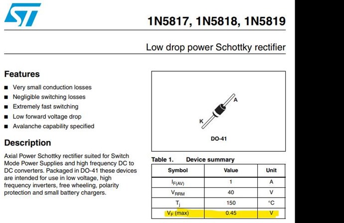
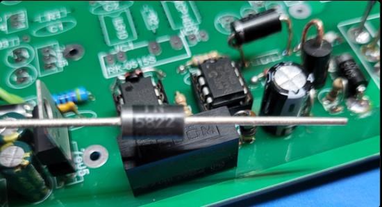
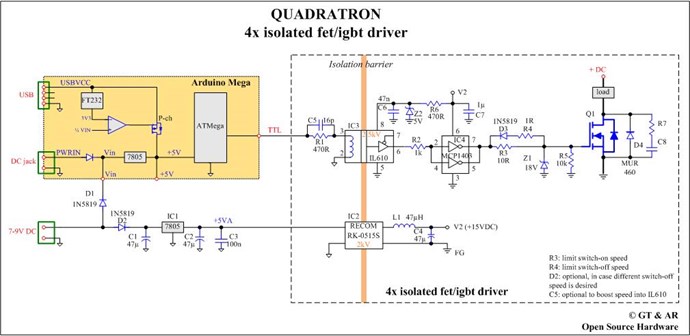
D1, D3, D11 are all IN5819 from the parts list. Make sure the MUR8100E specs match. But this may not be critical.
I was inclined to agree, but I ordered 1N5819 today to be consistent with the recommendation.
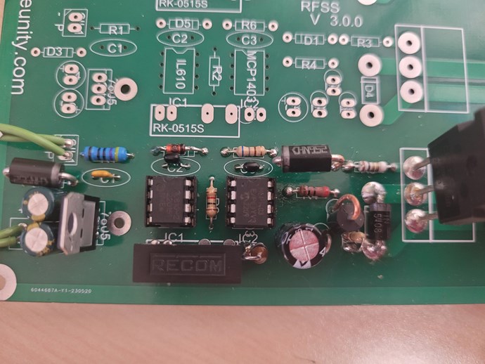
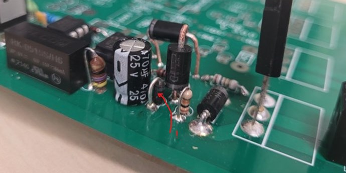
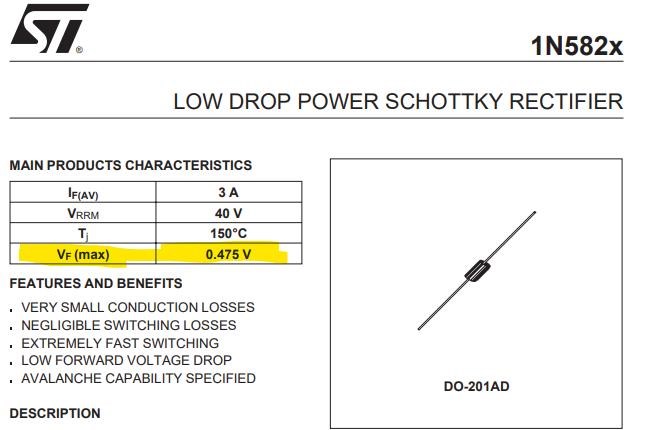
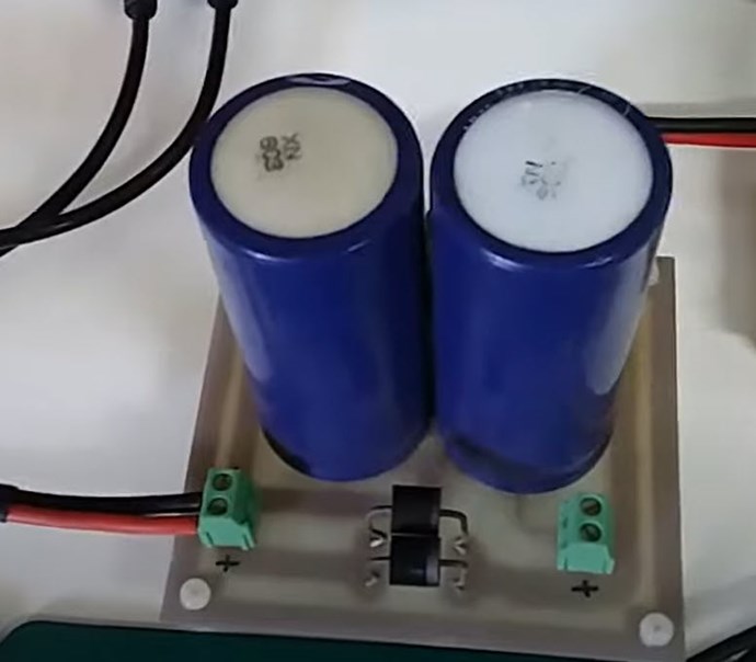
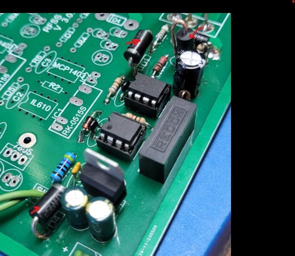
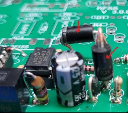
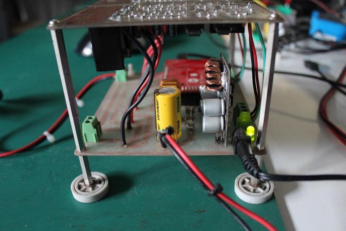
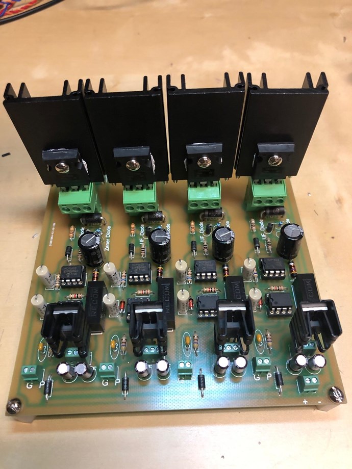
I located a stash of 1N5822 that looks like it might be in the same "58" family as the 5819 except that (at a glance) it has a higher current rating and so the leads have more meat on them. Because I couldn't wait, I ground them down so they would fit on the board and replaced the MUR8100E . Maybe I could have drilled, but sometimes when I do things it's because I don't know any better. The result should be the same.
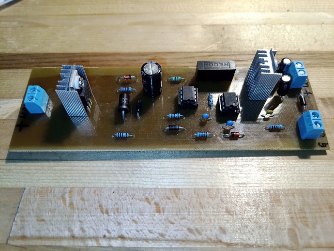
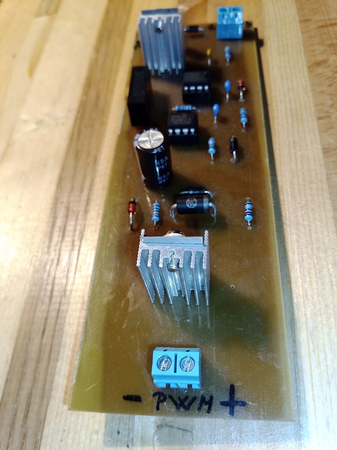
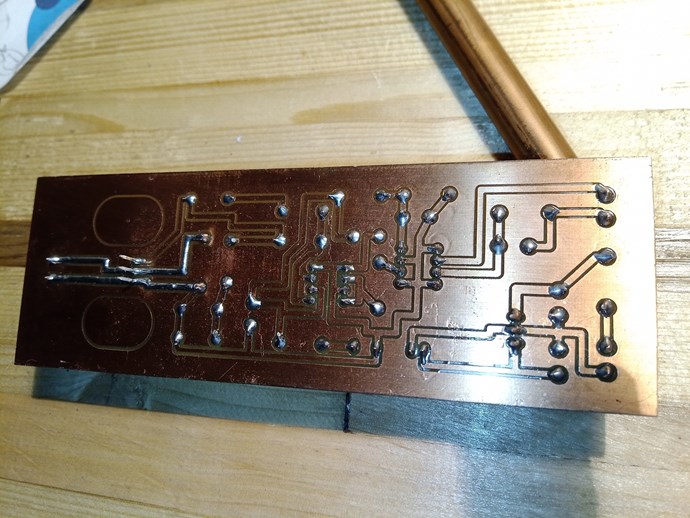
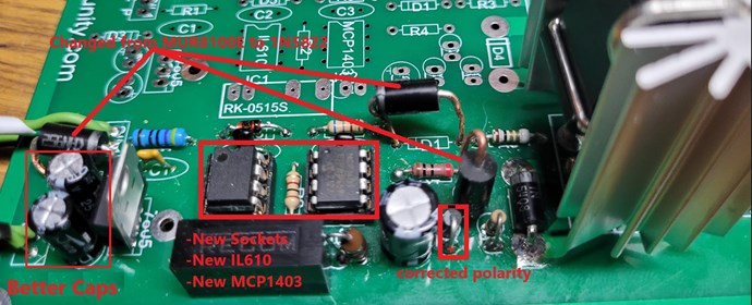
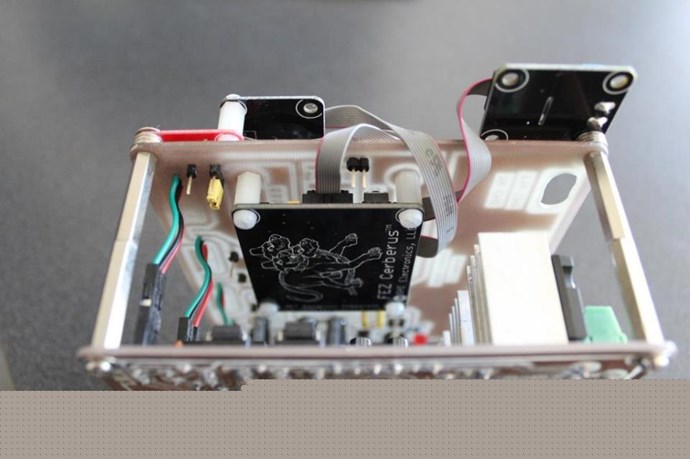
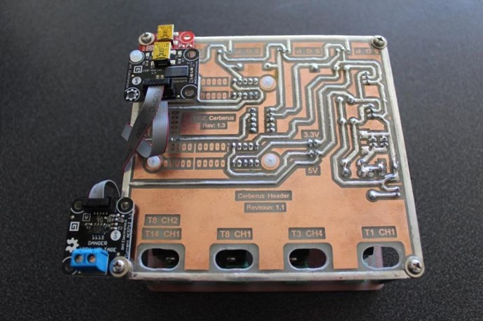
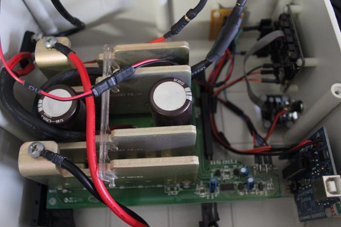
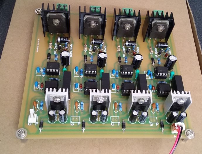
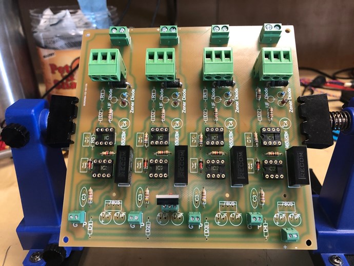
Here's a few photos after re-working.
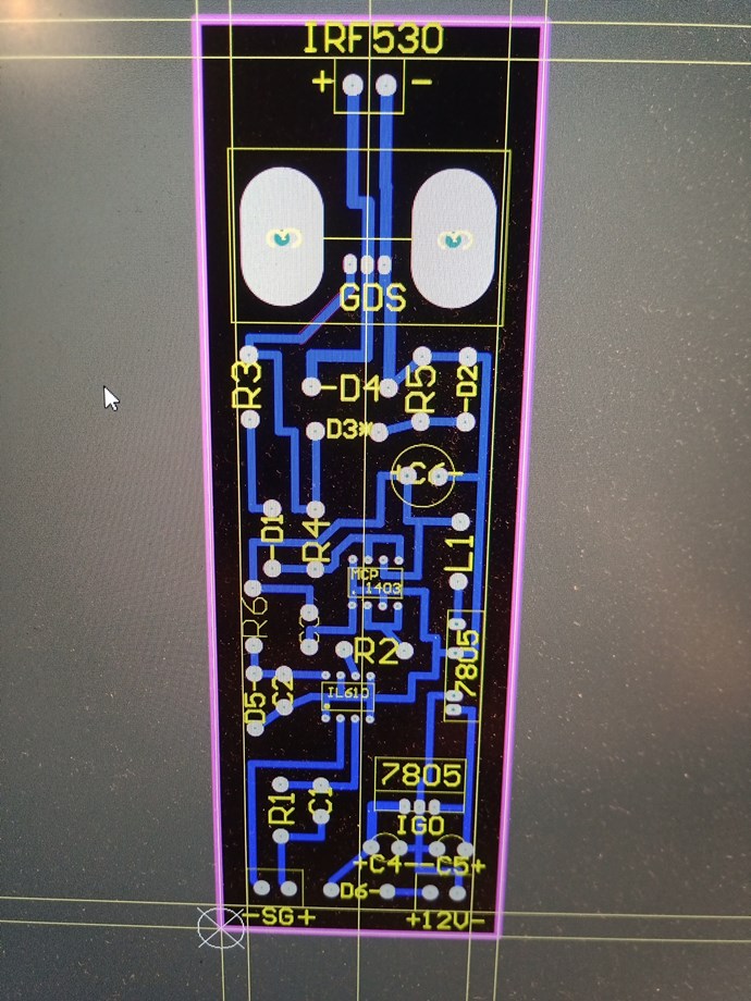
The D2 and D3 marking on screen print have been exchanged (not reversed, which would mean reversal of direction!)
Understood and thank you. Semantics matter. I swapped/exchanged them and maintained reverence of their Gnd terminal.
The input diode where the signal first enters the circuit is marked D11 in the diagram but is listed as D6 in the parts list. [And D6 is same part number as D1.] I hope it is clear now. 😇
Thanks for putting up with the confusion. Quite clear.
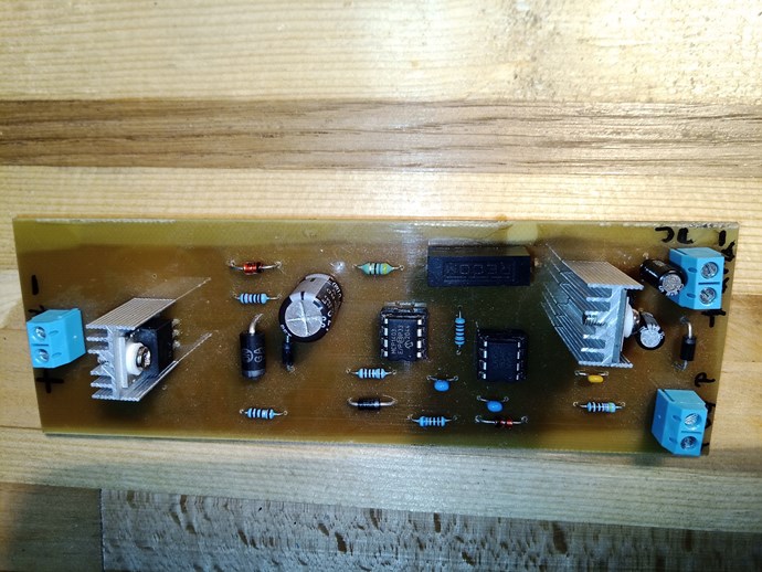
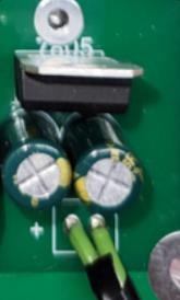
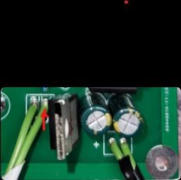
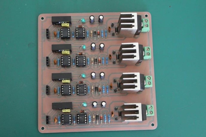
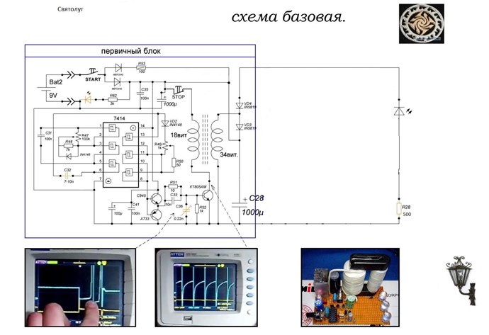
The only other bit (that probably isn't a cause for concern) is that on the original Quad circuit it calls for 47uF Electrolytic caps connected to the 7805 (C1,C2 of original quad image) but I see 100uF (C4,C5) being used on the image immediately above.
The original quad image also calls for 47uF Electrolytic as C4 instead of 470uF as C6.
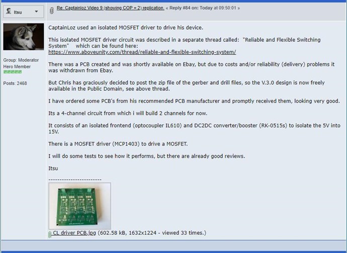
If you read the full thread, you will find that Chris and others have tweaked the circuit to further optimize it. Best to stay with what they have settled on finally.
I'm positive it in there as you say. In any case the caps here are absolutely the 100uF
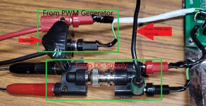
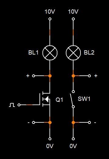
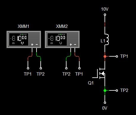
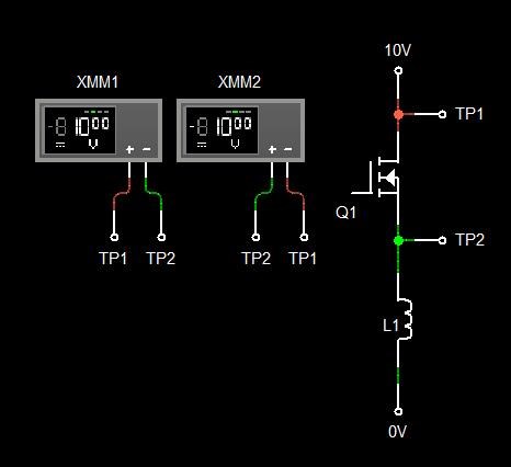
I connected the + output of the mosfet to the + of the PSU. The - of the PSU goes to the + of the primary coil. The output of the primary coil returns to the gnd/source. I only put 1V in.
This may not be enough to overcome the MOSFET internal resistance. You can safely put 3V for initial testing.
Ah ha. I will.
The PWM signal can vary to +10V max.
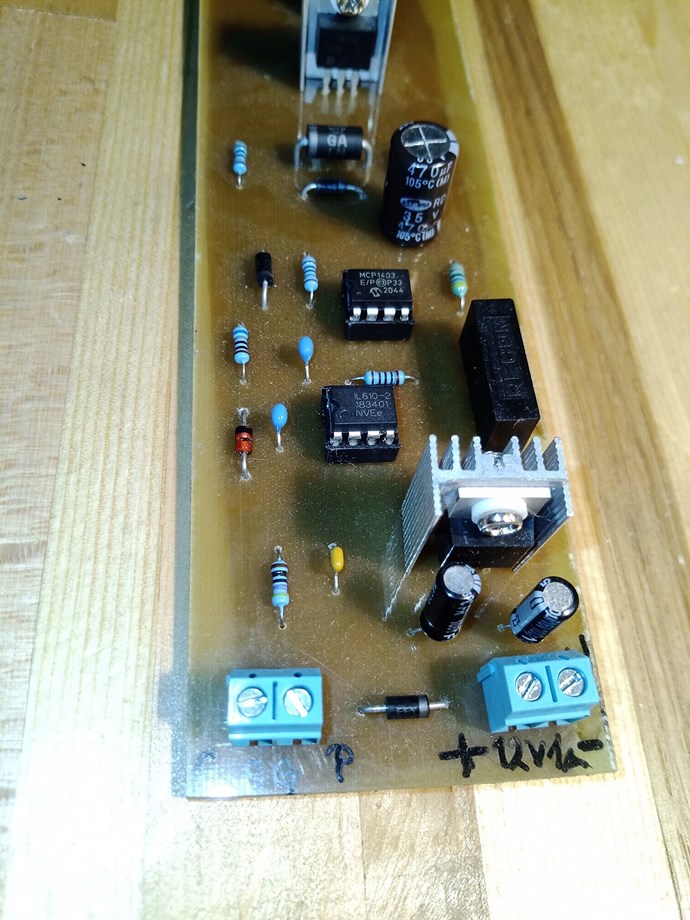
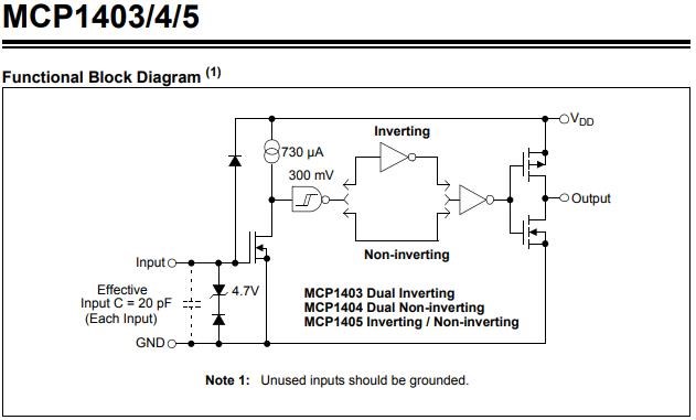
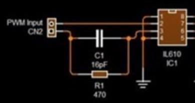
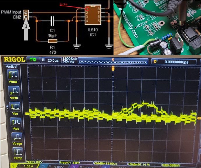
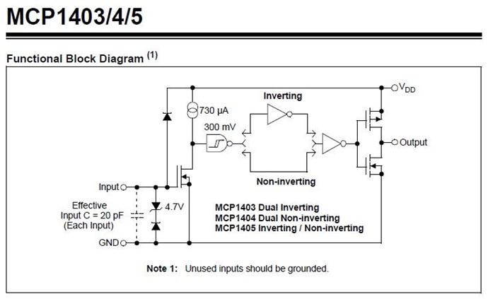
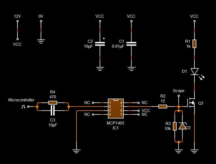
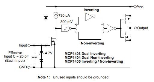
Please check if your input signal is coming into the pin maked "P". Put a resistor in between to limit current to the 20mA which is the maximum for IL610. Aim for about 10 to 15mA for safety.
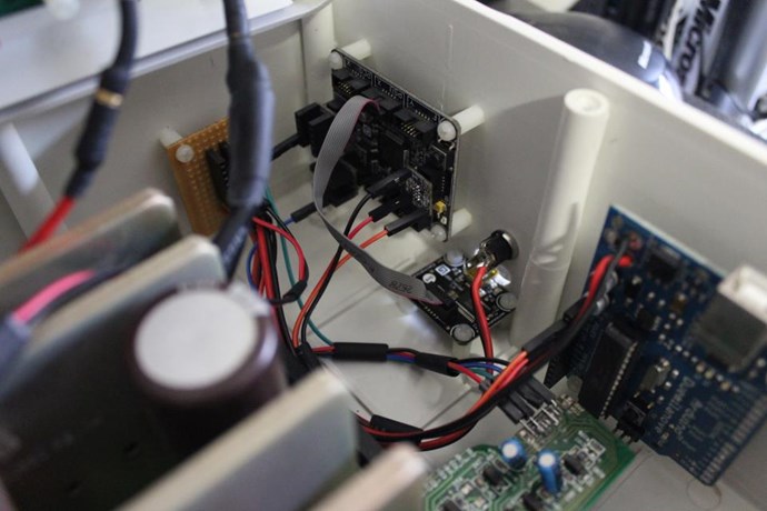
The PWM input is going here
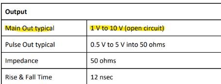
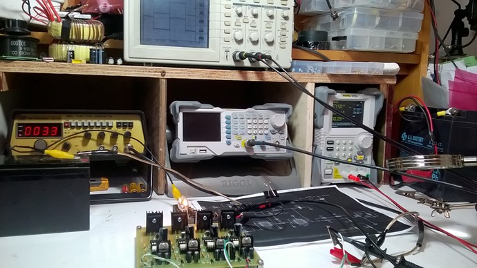
For what it's worth, this (BK Precision 4030) is the pulse generator I've been using.
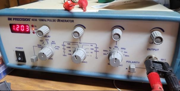
While set to the "INT RATE" it's 1-10V. With the XTAL it's 0.5-5V.
It didn't occur to me that I might damage the IL610 so I wanted to check.
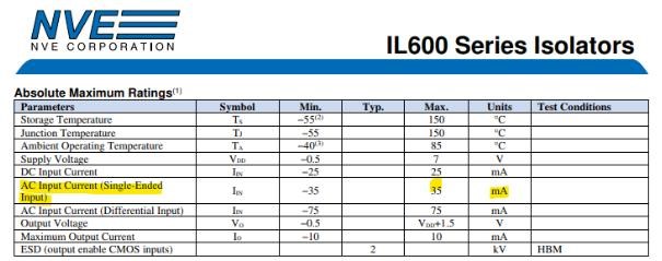
So with the installed 470Ω limiting resistor, if the input signal was 100% duty and the pulse generator was set 10V max the input current would be 10V/470Ω=21.2mA, correct? Famous last words but it shouldn't be a risk, right?
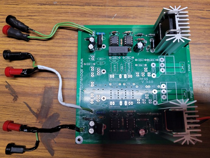
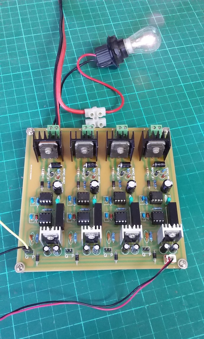
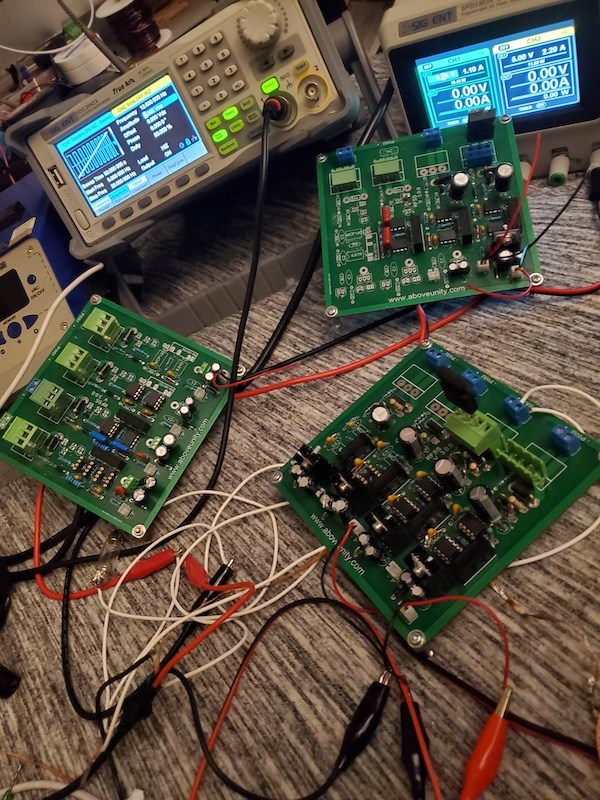
I'm powering the board with a 12V 1A wall brick.
Your 7805 then needs to dissipate nearly 0.7W. If it gets hot, do consider a heatsink. Or better, reduce your voltage to 7.5V.
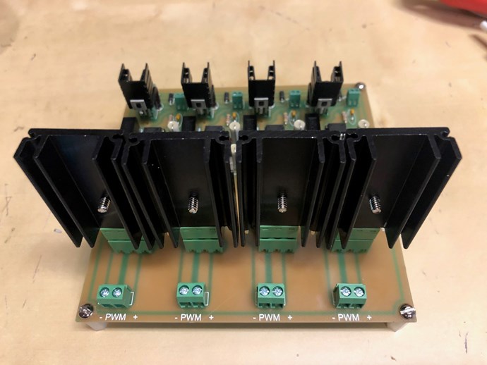
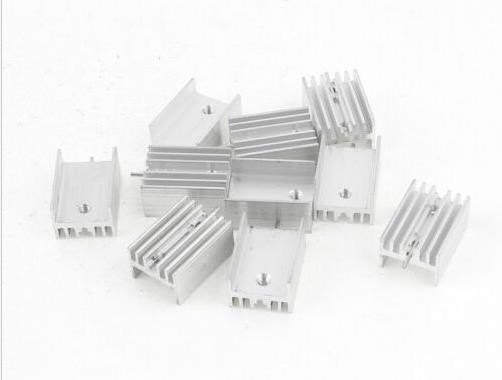
Sinks are inbound arriving tomorrow. I'd like to see if I can get it working with 12V but only for lack of a 7.5V in my drawer. I would change to minimize dissipated heat.
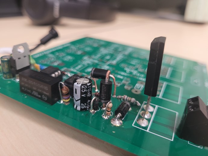
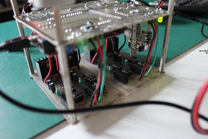
Finally, I would suggest to solder the MOSFET as close to the board as possible (unless you need the extra height for a heatsink).
The height is indeed for a sink. I can see how close I can get after.
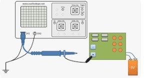
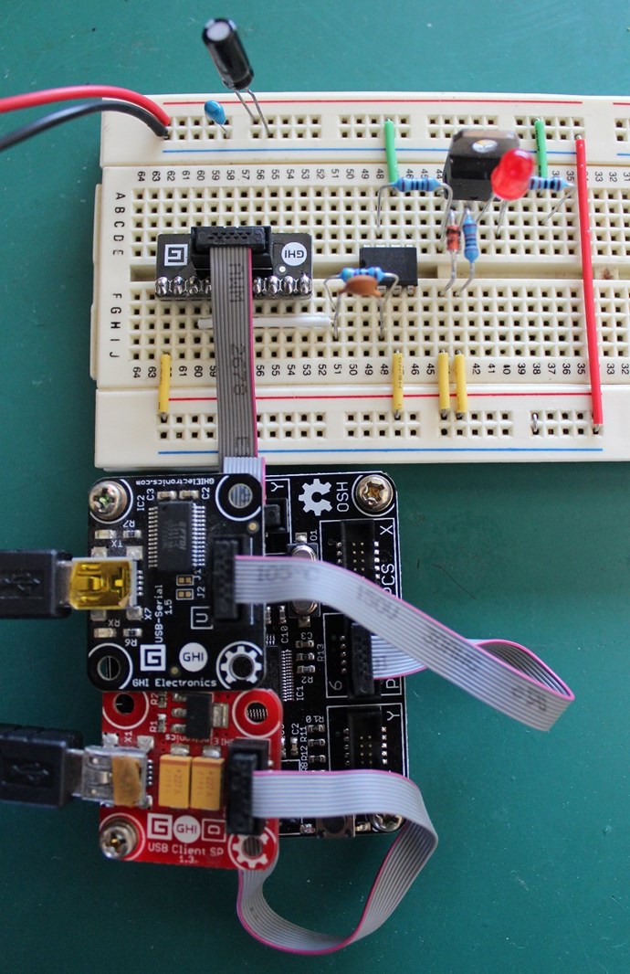
I had problems just by connecting the probes inside the isolated portion because the probe ground was breaking the isolation.
Be careful not to probe the input and output with at the same time since the ground pins will short them and short the isolation!
Test only the output portions with just one probe only while disconnecting from all else. Even then there is the ground loop through the scope. But it should work for basic debugging. Or you can use two probes to form a pseudo-differential probe and use only inside the isolated portion.
OK so it's not just me.
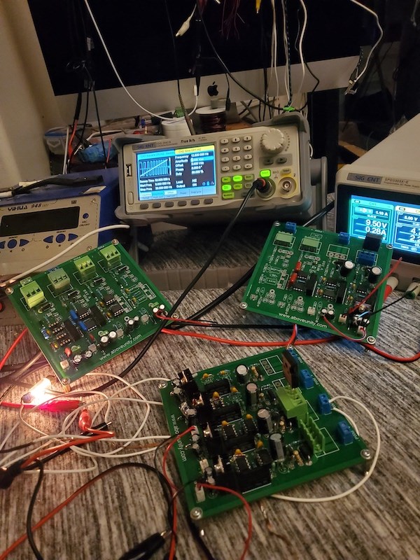
After changing out the UF diodes to the IN5822 I set the other (bench) DC supply to 3V and connected across the primary load.
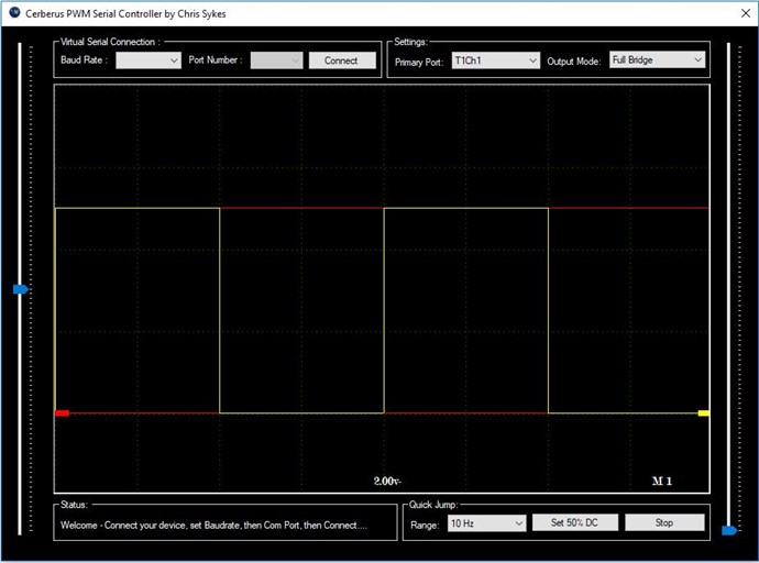
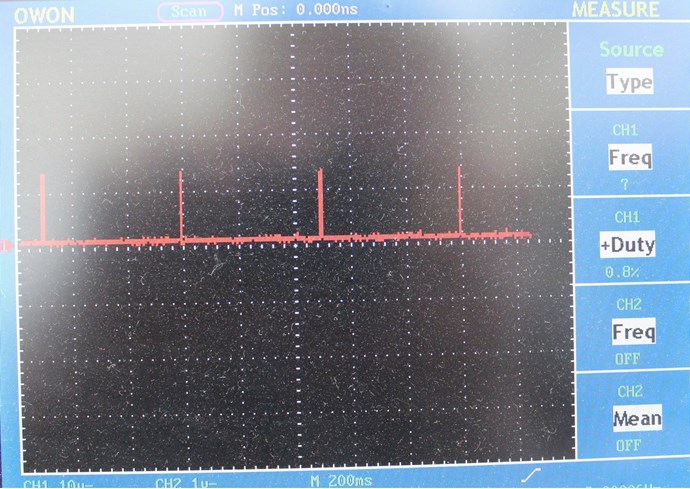
Honestly, not a lot has changed. I set the pulse generator to ~10% duty at 100Hz, 1Khz, 10Khz
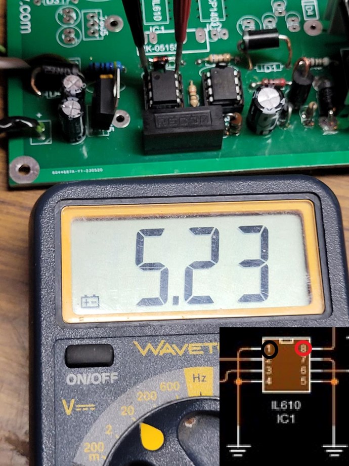
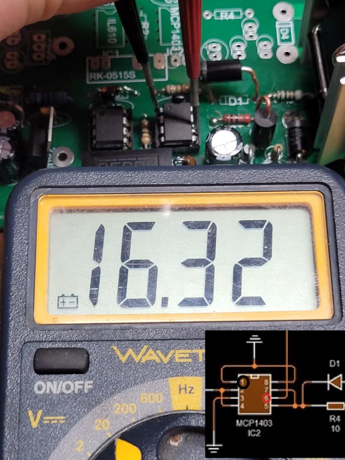
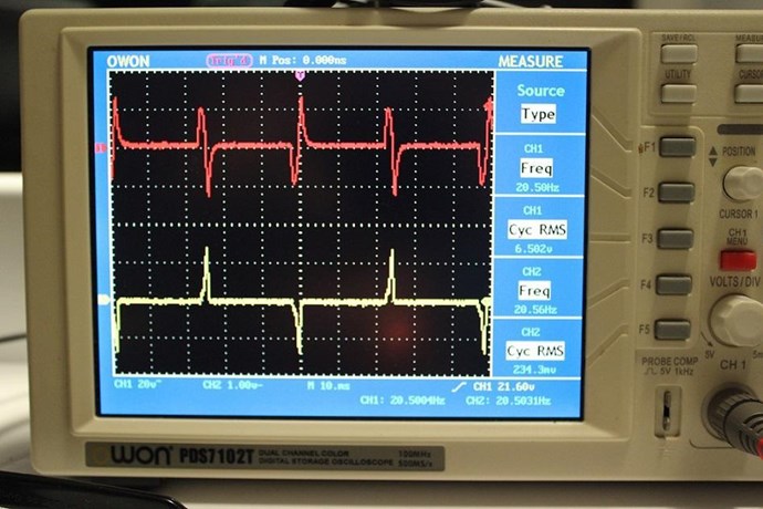
- I verified that the ~5V and ~15V were present where they belonged.
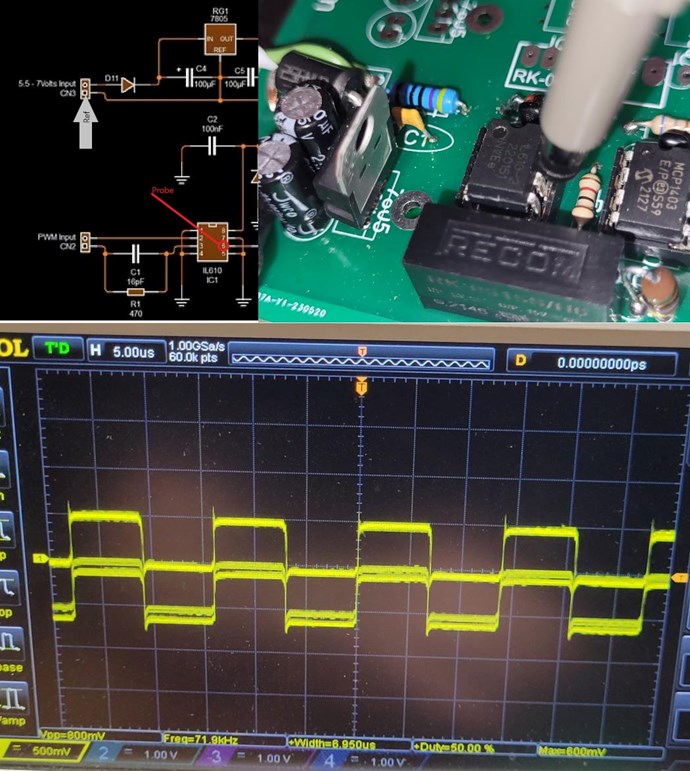
- set the scope to 1channel only and probed the gate and used the Gnd side of the 10KΩ (R5) as a Ref and didn't see anything resembling the input signal. I varied the pulse width to see if there was a change. It's like nothing makes a difference. Does this break isolation? I tried with no Ref but as you can imagine that was worse.
- probed across drain and sink and varied the pulse width. Nothing notable. Like always I tried to auto trigger.
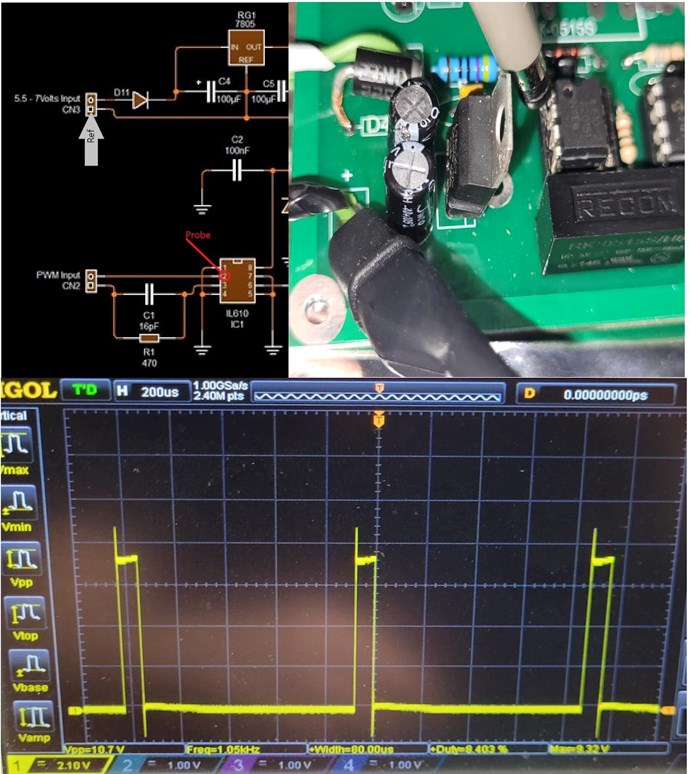
- I can see the signal going into pin 2 of the IL610, but I wasn't able to capture the output on pin 6 when using the Gnd pins 5/7 as a probe reference
- Got paranoid about the DIP sockets, turned everything off, did continuity checks from the top of all pins of each IC to the bottom of the PCB solder joint. About .5Ω for all of them (including probes) so I'm assuming there is proper contact.
For what it's worth I have the scope set to trigger on ch1 rising edge and it's set to DC coupling. If you think my issue is related to a scope setting I can try to rule it out, but since I can see the PWM signal from the benchtop generator I didn't think it was worth trying to troubleshoot the scope settings.
For context I had been using this thing with a different coil setup and I was able to get a light to glow. It seemed to have better isolation than this other thing. In both of those cases I was able to probe the coils and see significant voltage from a 5V drop across the primary. While I'm convinced this AU sanctioned switching circuit is the right tool, clearly I have work to do.
I do have access to HV differential probes and a high speed current monitor. I can break them out whenever but I don't think I'm there yet.
Just for my sanity I'm going to try another IL610. I can't reconcile why I'm not seeing anything on output pin 6.


.jpg?width=50&crop=0,0,50,50)

.jpg?width=20&crop=0,0,20,20 "fer123")