
hi fighter,
I copied your experiment with a large iron core and a small iron core.
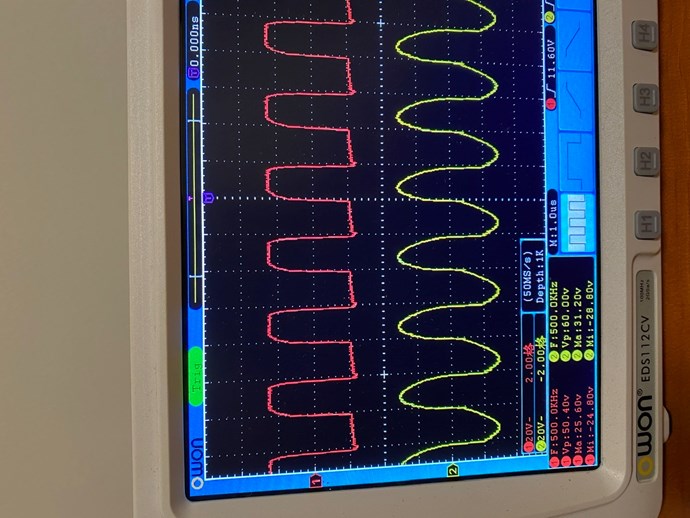
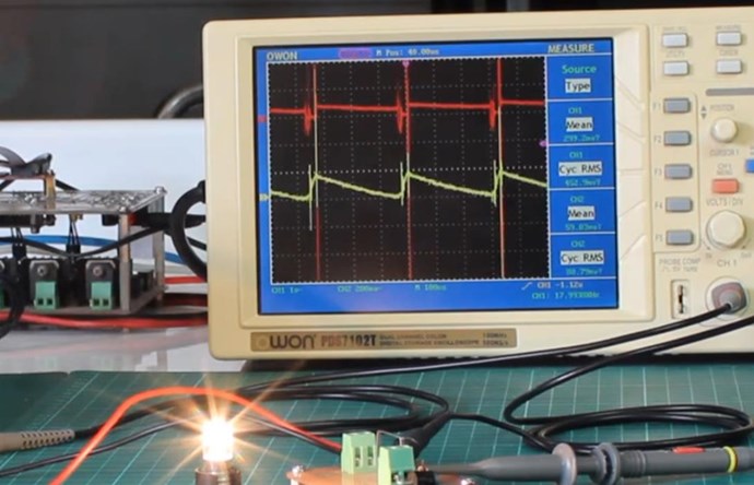
The oscilloscope shows the waveforms of the two coils.
I think it is impossible to form a standing wave in this situation.

hi fighter,
I copied your experiment with a large iron core and a small iron core.
The oscilloscope shows the waveforms of the two coils.
I think it is impossible to form a standing wave in this situation.


Hi,
How many turns each coil has ? Are they approximately 150/300 turns ?
Did you checked to make sure the magnetic fields created by the two coils are opposing ? Like creating two opposing North poles in the upper side of the core and two opposing South poles in the lower side of the core ?
Also did you searched for the optimal frequency for your ZPM ? The procedure for frequency sweep ?
I'm asking this because the wave forms are not looking like the ones generated by my ZPMs.
Regards,
Fighter

Okay, I have got the computer back. I will open a new post in a few days. I need to organize the videos and pictures first.

The key is to find a kind of magnetic material, after the coil generates a positive pulse, so that its parameter Br can exist for a period of time and automatically return to zero in a short time. And can the performance of such a magnetic material itself be maintained?
About "that kind of magnetic material", my ZPMs are using Metglas but probably it should work with iron cores too.
Details about my cores are available in the ZPM threads.
Regards,
Fighter
Thanks to the moderator for helping me open a new post
I will write my experience here
I started copying various battery-free devices from 2019
The first one I copied was SJR LOOPER
There are many drawings of SJR LOOPER on the Internet
There is one called Lasersaber https://www.youtube.com/user/lasersaber
He manufactured all kinds of SJR LOOPER equipment many years ago
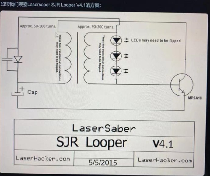
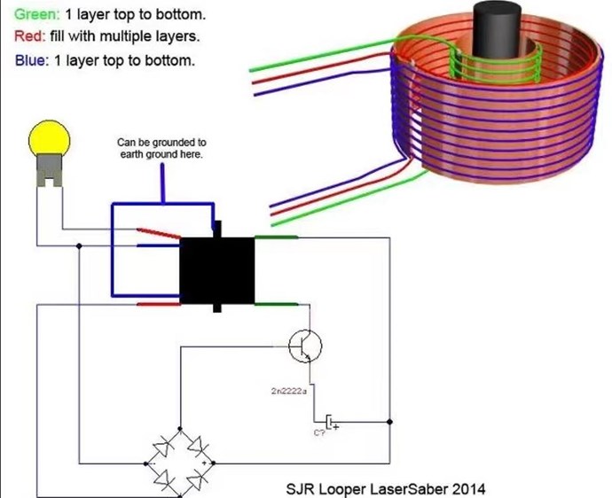
And refer to the Akula #5 video to wind the coil
After several experiments, I successfully copied SJR LOOPER
Please forgive me for the short duration of my video. I didn’t have the habit of recording experiments with videos or photos before.


Although the power of the SJR LOOPER I made is very small, but the LED can work for at least 6 hours
Although this is a joule thief circuit, it gives me a lot of confidence
I started copying Akula 0083’s equipment, I copied the Akula #4 device
Until now I have not successfully copied the akula #4 device
I think the key to akula circuit is 3 parts
1. The circuit control part is BJT or MOSFET, so I try various types of switching transistors
2. The winding method of the primary and secondary coil, I also tried every winding method I can think of
3. The choice of iron core, I tried thin silicon steel sheet, ferrite, amorphous
But I still have not successfully copied it, although I have tried various methods
Until recently, aboveunity.com was able to open normally
I watched the videos of MR.CD and MR.FIGHTER repeatedly, and tried to copy the ZPM equipment of MR.fight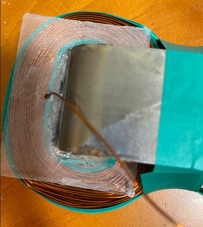
Although it has been unsuccessful, I will continue to try, starting from copying various devices, using the method of elimination, and gradually approaching the truth.
MR.Chris says " focus on the machine and what it is doing and what it needs to do. In these machines, resonance is very important, and I believe you have not hit resonance yet. Try not to get ahead of yourself, concentrate on the machine and what the machine is supposed to do. The fine details are very important, missing steps will result in failure."
Thank you very much!
I plan to start step by step according to MR.Chris’ method

I haven’t really succeeded in making a cop>1 device so far, so I can only recommend a book
《Secrets of Cold War Technology》
https://magstar.eu/wp-content/uploads/2020/11/Secrets-of-Cold-War-Technology-by-Gerry-Vassilatos.pdf
The first chapter tells the history of Nikola Tesla
As a Chinese, I don’t know much about many international conventions and various laws.
Piracy is rampant in China, and even most of the mosfets I can buy are fake and inferior.
I don't know if my recommendation of this book will violate the law.
Hey Scalar wave interference,
We will help you, if you focus your efforts on one machine at a time, and pay special attention to the details. It truly is not hard, it just takes some dedication, some focus and some attention to detail. We will help you if you can show us you're really keen to learn and achieve this goal.
You started Fighters ZPM, so I would really like to see this replicated properly and accurately, showing Results we have seen already.
We pride ourselves on the Advancement and Evolution of All Human Beings, but when they are ready. So, we help when others are ready, they come and we help. We strive for Evolution, we try, and that's all anyone can ever do!
Please understand, we have had many hundreds of trouble makers, in our achievement to abolish Trolls from our Forum, we have had many disgruntled Trolls come here and make trouble, so we Hit the Big Red Button, and Delete them! Please don't become one of those statistics!
Best Wishes,
Chris

From my experience, I know that this world is not what they say. There are many 7-8 year olds around me who can recognize the words on the paper in their hands instead of looking at them with their eyes. They even use The ears can also hear the words on the note.
Therefore, I think this world has not only the physical world, but also other worlds.
In the words of my friend, we live in a sea of energy. There is inexhaustible energy.
I still can't use the inexhaustible energy, just because I haven't got the "key" yet.
Hello #Fighter #Team, Can you please tell me what length of wire did you use?
---Chris,as your AMCC core is similar with Fighter's....perhaps you can help out also. I am buying the materials needed and I see , 10 m ,30 m ,100 m magnet wire etc. I do not want to make the wrong purchase. So ,on an AMCC core in that size range..what kind of lengths per coil did you use (aprox) Thank you very much.
@Melendor
You can buy more of various diameters. In China, enameled wires are sold by weight. I also don't calculate how long a coil is wound with many layers.
@Scalarwave,
Please refrain from posting to threads that you have been kindly asked to refrain from posting to.
I have locked Fighters Threads now, Fighter will un-lock when he sees fit.
Please respect the Members Here. If you do not, I will have no choice to stop you posting. Please focus on the task at hand and make steps to reach your goal. As I said, we will help you if you show you are putting the effort in.
We have Threads on Cores here on this Forum, please browse the Categories, or one direct link is: AMCC C Cores Suppliers
I try to use the analogy, every day of delay is a day lost
Best Wishes,
Chris
Hi Melendor,
Wire Length is easily calculated, simply Turns x Average Circumference. Average Circumference is Min + Max / 2.
Circumference = 2 π r
For Square or Rectangular Coils its just Add all 4 sides.
Lets take this coil:
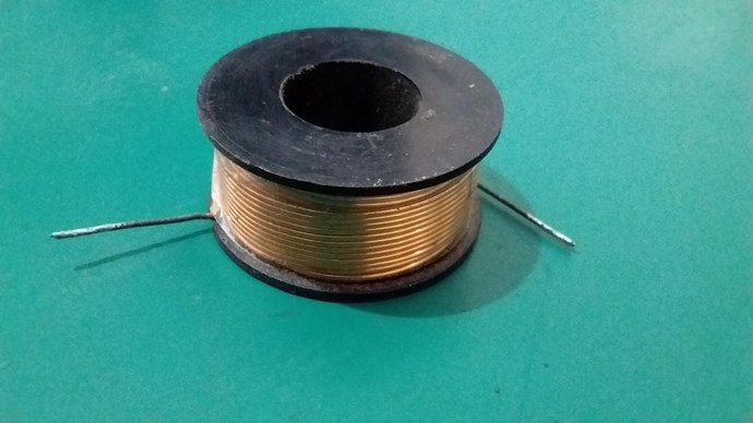
We have the parameters:
Now we calculate:
Now get the Average: CMin + CMax / 2 = 79.325214503142277mm
Now multiply by Turns, 180, so: 79.325214503142277 x 180 = 14278.538610565611mm or 14.278538610565611 Meters.
Make sure you add some more onto the Length, as you will need Output Terminals.
Of course, the Core you purchase will need to have a simple calculation done like so.
You have read all the threads, so you know, already, how many turns and what Core Sizes we use. When starting, I have suggested to just make a start and work with what you have available, looking for effects only first. This is the best way to start. Other wise people expect the first machine they build to give them Megawatts and when it doesn't they loose interest! The Experimenter must work toward the end goal, making progress in the form of little steps, like Sir Richard Feynman said: "Little Steps for Little Feet"
I would really like to see some work, some solid experiments from the new members here!
Recently, Amin and AlteredUnity have made progress, two of some 14 new members, not very good odds is it?
Please guys, we really want to see experiments, not post after post of nothingness!
Best Wishes,
Chris

Hi,
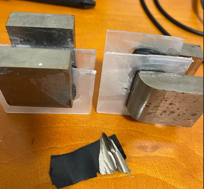
According to the drawings provided by Chris, I made a POC circuit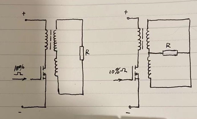
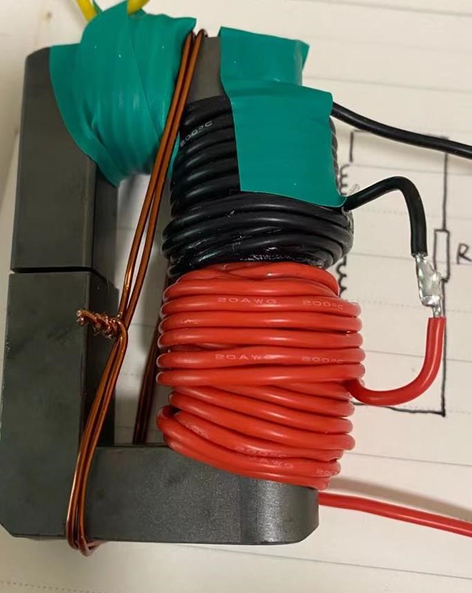
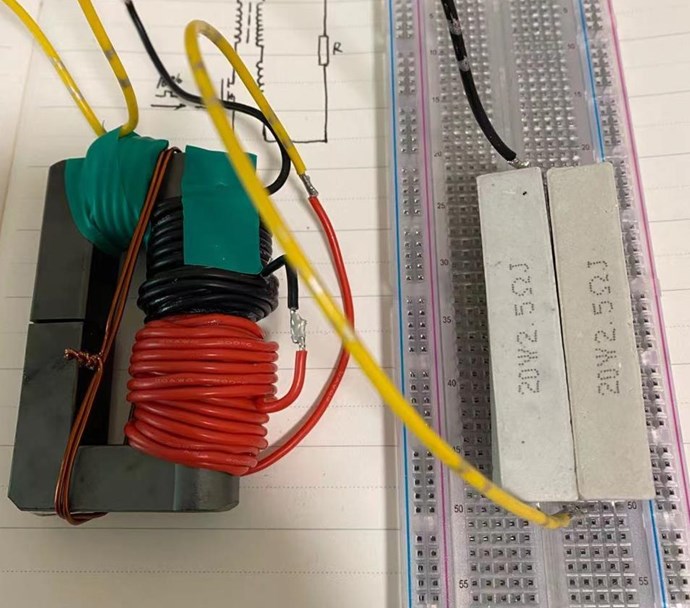
Some glue was used, so it looks dirty
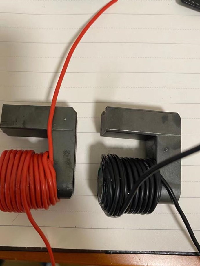
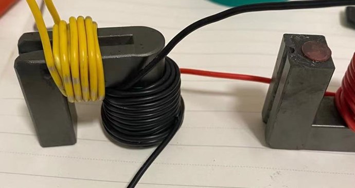
The yellow input coil has 9 turns, the cooperative output coil has 40 turns in red and 36 turns in black.
The model of mosfet is irfp250n
The initial output voltage of the DC power supply is 3v, and the current is 0.5a
The output rectangular wave of the signal generator, the duty cycle is 10%, and the initial frequency is 300hz
But the pulse voltage at the center point of the cooperative output coil I got exceeded 1000v, which also exceeded the range of the oscilloscope.
I will continue to adjust in the evening (China time)
I hope to see the appearance of sawtooth waves!
God bless me!
Is there a problem with the oscilloscope I am using? Or is it disturbed by the high current generated by the POC coil? I'm going to have dinner first, and I will continue at night.
Hi Scalarwave,
I thought you were Replicating Fighters ZPM?
If youre Replicating My Partnered Output Coils now, how close do you think you are to this:
If we had to work out a percentage how close you are? How much?
Scalarwave, I am trying to be patient with you, but I can see you have done very little research and your attention to detail needs some attention!
Soon, I am going to drop you back to a moderated account for a little while, if your going to go off on tangents all the time.
I suggest do some more research and get yourself up to speed with what we are doing.
Filling Threads with Nothingness is not acceptable here, if you want to do that, go to one of the other forums.
BUT, seeing your experiments is a welcome relief. If we can just get you up to speed with our work?
Best Wishes,
Chris
Scalarwave, if you're trying to replicate Partnered Output Coils there are some things to do:
Be careful, in the center of the partnered output coils high voltage peaks will appear.
If there are real 1000 volts spikes you could damage your oscilloscope.
Follow in details the schema which Chris provided, allocate some time to see the videos made by Chris, pay attention to details.
Don't do things in hurry and you will see the results, many experimenters here replicated POC successfully.
@Chris, if I missed something or there's something which should be corrected in the list above please feel free to update it.
Regards,
Fighter
Fighter is spot on!
Please Scalarwave, we are trying to help, but you also need to help yourself by doing some required study.
Best Wishes,
Chris
I always hope to find the truth in the simplest things? Whether it’s your cooperative output coil, MR.Fighter’s ZMP, or MR.CD’s device, I want to find simple and intuitive truths from it.
Maybe the video I made makes you think I’m just doing it without thinking
However, all my text is translated through Google, I am afraid you will not understand what I said
So I can only do more experiments
I insisted on it for more than a year, and I definitely didn't come to you to make trouble
I also have a lot of ideas, but I can’t express them
I don't know what my behavior makes you think I'm a troll
Chinese people are not all bad guys, although many Chinese are breaking the rules all over the world
But definitely not me
I just want to make a device with cop>1
Thank you for your understanding
I have been studying very seriously, even after downloading your video, I will translate it, using the remaining time as much as possible to enrich myself
Will downloading your video arouse your disgust, I can delete it immediately
Hi Chris
It seems google translate Made me misunderstand what you mean!
I have read many posts. Since you said that as long as there is a cooperative output coil, only a positive pulse, etc., I think that whether it is your POC or MR.fighter's ZPM, as long as I find the sawtooth wave, I will It can be considered that I almost found a way to COP>1
In my opinion, no matter who it is, as long as it can achieve COP>1 is a good way
There is a Chinese proverb: "Whether it is a white cat or a black cat that can catch mice, it is a good cat."
Google Translated
Thank you for understanding
Scalarwave, we are aware that using Google Translator can result in a lot of misunderstandings.
It's okay, as long as you show here how your experiments evolve we will be able to help.
Here nobody judge people based on nationality, we are here from all over the world, but we had troubles before with some trolls and that's why we are cautious.
Take your time, watch the Non-Inductive Coil Experiment video series and look for details there.
You're an experimenter and that's a good thing, we'll try to help as much as possible.
Regards,
Fighter

Thanks MR.Fighter!
Thank you very much.
I have been doing experiments alone, and I have also spent a lot of money.
I have always been upset that no one communicates with me, and no one can guide me when my ideas reach a dead end.
Therefore, there are all kinds of strange ideas.
For example, I always think that akula uses very special BJT. For example, I used to think that your "black box" is the biggest secret, hahaha
No secret, my "black box" is the simplest device ever, it has just two channels and two MOSFETs inside and with ZPM I'm just using one channel so just one MOSFET. There is also a cooling system (two fans) for the MOSFETs radiator (the cooling system has a separate 12V DC power source from a cable coming to the back of the box), a switch and a LED for turning on MOSFTEts switching and another switch and another LED for turning on the cooling system. That's all. Its schema can be found in the ZPM thread, also on my YouTube channel there is a video where I show it opened up for MOSFETs upgrading.
All the data that I have about ZPM, all the experiments and all the details are public in the ZPM threads.
I don't hide things, on contrary in time it took me probably hundreds of hours to organize the data, the experiments and the results and to present them to everyone.
Regards,
Fighter
Just to clarify I've made a schema of the DC source, the "black box" and the ZPM with a light bulb as load.
What you see in the black rectangle is the content of the "black box" and that's how it is connected to the DC source, to the signal generator and to the ZPM.
I just ignored the presence of the cooling system, the switches, the LEDs and the connectors from the front panel, they're not important in the functionality.
I ignored the second channel and the second MOSFET as I'm not using them with ZPM, I'm using just one channel.

So you see, it's nothing secret about it and it's simple
You'll see similar schematics like this in the ZPM thread.
Regards,
Fighter
Yes, MR. Fighter
Thank you!
I now know what's in your black box
What I have to do now is to confirm that I can get a valid sawtooth wave in the oscilloscope
Instead of guessing and using any "mysterious power" to achieve COP>1
Step by step to achieve the goal
@ScalarWave
There is a lot of "Noise" in your mid / thoughts...please Stop...clean it a little bit.
COP > 1 = Transformer + 1 more coil
Transformer MUST be EFFICIENT else it does not work.
Efficient transformer = 1 winding ON TOP of the other !! Input 1 W output 0.8 W (0.2 are losses)
If the wire has INSULATION , the efficiency of the transformer will go down.
If it goes down too much , even if you get the Triangle wave from the 3'rd coil.....it will not help....because you will still be under 100% efficiency of COP < 1
If you do not know the basics ...you can get killed....This is not child's play.....and please be careful with that 1000 v inductive spike....That will not end well..
I wish you all the luck.
*Melendor the wizard
hi Melendor,
thanks for your reminder
I also know that there is still a lot of power output on my DC power supply. Like MR.Fighter, there is only a very, very small output on his DC power supply. I still need a period of adjustment.
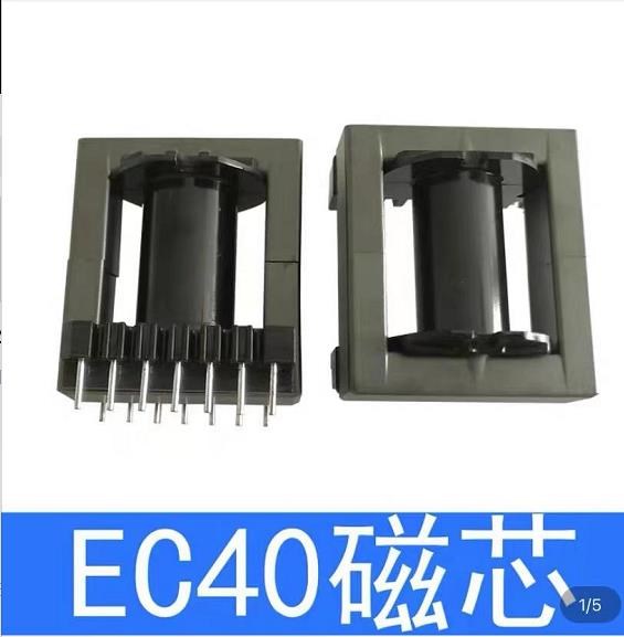
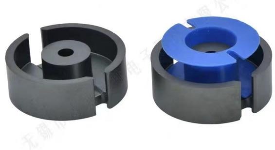
I bought some plastic rings for winding copper wires。
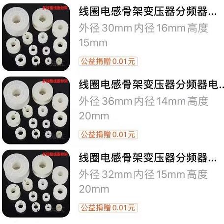
In order to make the transformer more efficient, I don’t know whether it is possible to use some special-shaped magnetic cores with very small leakage flux.
I need to test
hi,
I am considering the presence of thousands of volts at the center of the cooperative output coil.
That is to say, the two pulses did not form a bucking, that is to say, a Bucking Oscillator was not formed.
1. Is this caused by the distributed capacitance inside the POC coil?
2. The interaction between the two POC coils is uneven, caused by one strong side and weak side?
3. How long does the transmission of the magnetic field exist? But I think electromagnetic waves are light, and light has speed. The magnetic field that composes electromagnetic waves should have no time limit for transmission. There should be only changes in intensity and no time limit.
4. Is it possible for the position of the center point of the POC coil to convert all the high voltage into current?
5. Why does static electricity have such a high voltage? How is it different from the current in the wire? Is the high voltage formed by the POC coil or the radiant energy formed by the entire system different from the current in an ordinary wire?
But what I have to do now is to adjust the POC coils so that the two coils are as close as possible in terms of parameters.
The above questions are just sent out with some thoughts, some have my answers, and some don't. Don't dare to talk about my personal answer for fear of misleading others.
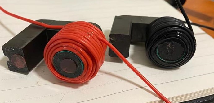
Scalarwave, if you're trying to replicate Partnered Output Coils there are some things to do:
- the output coils should be equal (the same number of turns), meaning the black and red coils;
- you should check that the black and red coils are generating magnetic fields opposing to each other, that's very important;
- the yellow coil which is your input coil should be on top of one of the output coils (the red coil or the black coil, you choose which one);
Hi MR.Fighter
Regarding the cooperative output coil, whether the two coils are the same length, I still can't fully confirm.
1. With different winding methods, CW and CCW, the direction of the magnetic field generated by the coil will not be the same.
2. The relationship between the primary coil (input coil) and the magnetic core is that electricity generates magnetism,
The relationship between the magnetic core and the POC coil is that magnetism generates electricity.
3. The time for the pulse to travel inside the wire.
I remember that the transmission speed of electric current inside the copper wire is 6 inches per nanosecond,
This does not include the influence of the magnetic field on the speed of the current.
The pulse time is a very short nanosecond time,
It is very difficult to generate the right two interacting pulses at the right time and at the right place.
I think that for coils wound in different ways, this is not just a problem that can be solved by adjusting the frequency or duty cycle.
So, this is why many "trolls" will completely deny this technology.
This is just my personal opinion!
It may be that I didn't find a suitable method or a suitable "key" to have such an idea.
I have been doing what I should do.
Denying my own ideas is something I have been doing.

yes,the black and red coils are generating magnetic fields opposing to each other.Otherwise, I will not detect thousands of volts at the center point.
But, it is difficult to make these two positive and negative pulses form a standing wave.
In my opinion, it is as if two strong magnetic N poles and N poles are paired together, and they will easily slide apart.
So I think it gives us very little space to operate.
Or there are some other tricks that can be used.
I need to find.
By the way, does your re-made smaller ZPM work properly?
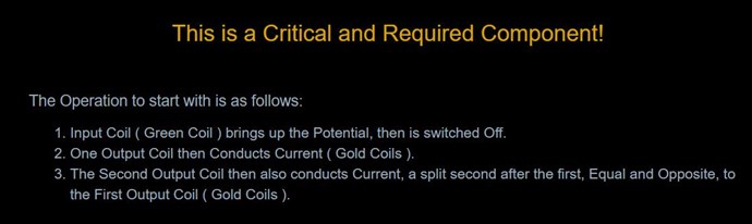
Hey Scalarwave,
Please Follow:
The Circuit:
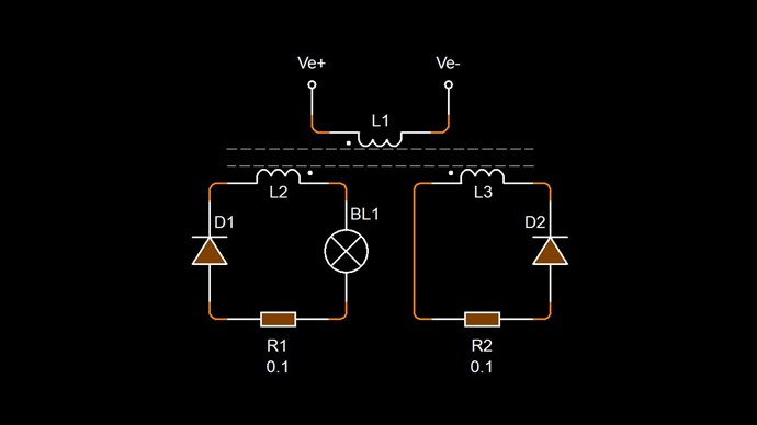
L1 is your Input Coil:

Please do not deviate!
Best Wishes,
Chris
By the way, does your re-made smaller ZPM work properly?
Yes, my ZPM replication ("ZPM-2") is working as expected, but it's not smaller, the core has the same size.
Are you referring to this one (the one with red triangles on it) ?
(link to larger image here)

You may see how it's working in the Romanian ZPM (Zero Point Module) - Enhancements Stage thread on 07 March 2020.
Regards,
Fighter
hi MR.Fighter
I always thought that zpm2 is a smaller device
I like small things
Especially the kind of small but powerful device
It can be used as a power bank with unlimited charging
@Chris
MR.Chris
Your non-inductive coil series video, I have seen the sixth episode
I have been following and will not deviate
Two consecutive holidays (Mid-Autumn Festival and National Day)
I have not received my purchase yet
Half a month has passed!
The manual winding machine I received before was damaged in transit, and I had to use an old winding machine.
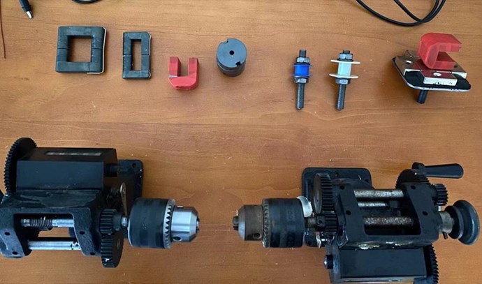
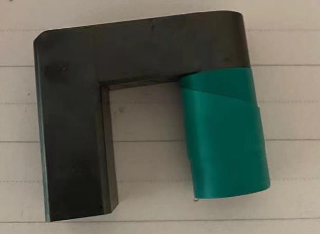
I used thin iron sheets and strong magnets to make a fixture for the winding of U-shaped cores.
The strong magnets is very strong and will not loosen during use.
Strong magnets should not have any effect on the amorphous magnetic core, right?

I followed the settings of MR.fighter and copied it completely
But it did not achieve the same effect as MR.fighter
Even the waveforms appearing at the three ports of the cooperation coil are the same
What is the reason for this? I am really not sure.
Do I still need to adjust the coil or other aspects?
Hi Scalarwave,
ZPM can be replicated, all I can say is that an member of the AboveUnity team has successfully replicated it but I cannot say more without his permission.
I see you're providing just 7-8 volts on input, try go higher with the voltage, I use 25 volts.
Is the signal generator providing sinusoidal signal or rectangular signal ? I use rectangular signal with 25-50% duty-cycle to drive the MOSFET.
Then do a frequency sweep as I do here:
When ZPM will start working at its optimum/resonance frequency you'll see your input current (amperes) going down (like just 0.03 A consumption), you'll see ZPM's specific waveform on your oscilloscope and you'll notice the MOSFET will get very hot, the radiator you use on MOSFET will not be enough to dissipate that heat.
Please check my videos and use the input parameters I shown in these videos (voltage, rectangular signal, do the frequency sweep procedure).
Edit: please make sure the magnetic fields created by the two coils are opposing to each other, that's very important.
Regards,
Fighter
Hello Scalarwave,
All the things Fighter has said above are true. 25% duty cycle , Square wave , more voltage to push a greater curent into the coils , Twin polarity on the coils N-N above and S-S below.
I want to add that your oscilloscope is Frozen. You can not Probe 3 different sides of a circuit..and get 0 modification on the scope. You probed v+ , middle of the coils and the source of the MOSFET without any movement on the scope monitor. You used the TRIGER Funktion to capture 1 single wave...and now you must hit Cancel or Auto. Love your coils and experiment. You did a great job. ~~~Melendor the Wizard
Hello everyone, I have been reading and studying recently, and now I know that it is very difficult to achieve overunity, and I will persevere!
Hi Scalarwave,
When you say:
it is very difficult to achieve overunity, and I will persevere!
This statement is really not true, not in the full sense of the meaning! If I said it is very hard to Generate Energy from an electric "Generator" would you believe me? I would expect you to start asking me why, and questioning my approach!
Stick to the rules:
Sticking to these three rules, it is an easy task to achieve Above Unity! Many have done is already! Some have deleted their successes, because they had sprightful moments!
Jagau has shown a very simple experiment that gives everyone here a huge leg up!
IMPORTANT: Force your mind to think Simply, do not let over complication slip in! This is where most seem to come unstuck!
Best Wishes,
Chris
The common mode inductance is a cooperative output coil through suitable wiring
This is a typical device. From the position of its primary coil (differential mode coil in the middle) and secondary coil, it can be seen that this device does not transmit and amplify energy through magnetic induction.
Although piezoelectric ceramics can generate a maximum pulse of about 20,000 volts, it can be seen from a few simple electronic components that the internal high voltage of this device will not exceed a few hundred volts when it maintains continuous lighting of the LED.
Although I haven't tried it, if I directly "ignite" the secondary coil, that is, the POC coil, with piezoelectric ceramics, I can be sure that the LED will not be lit continuously. So what exactly does the primary coil do? What exactly does a single-tube self-excited circuit do? What exactly is the energy transferred from the primary coil to the secondary coil?
I have seen many videos about kapagen, MEG, Don Smith device and many more. There are only a few well-known gentlemen who can really make OU devices. Many devices either fail completely without context, or are "on the road to success" all the time. Is it that hard to make a device truly run itself?
please forgive my chinglish!!!
Hey
When you mention
Although I haven't tried it, if I directly "ignite" the secondary coil,
Have you tried it or haven't you tried it?
It's hard to understand?
Jagau


No one online at the moment
Past Visitors: 0 | Live Visitors: 0
3D globe widget by: Chris Sykes
In physics, scalars are physical quantities that are unaffected by changes to a vector space basis. Scalars are often accompanied by units of measurement, as in "10 cm". Examples of scalar quantities are mass, distance, charge, volume, time, speed, and the magnitude of physical vectors in general.
You need to forget the Non-Sense that some spout with out knowing the actual Definition of the word Scalar! Some people talk absolute Bull Sh*t!
The pressure P in the formula P = pgh, pgh is a scalar that tells you the amount of this squashing force per unit area in a fluid.
A Scalar, having both direction and magnitude, can be anything! The Magnetic Field, a Charge moving, yet some Numb Nuts think it means Magic Science!
Hello my children. This is Yahweh, the one true Lord. You have found creation's secret. Now share it peacefully with the world.
Ref: Message from God written inside the Human Genome
God be in my head, and in my thinking.
God be in my eyes, and in my looking.
God be in my mouth, and in my speaking.
Oh, God be in my heart, and in my understanding.
We love and trust in our Lord, Jesus Christ of Nazareth!

More than anything else, your contributions to this forum are most important! We are trying to actively get all visitors involved, but we do only have a few main contributors, which are very much appreciated! If you would like to see more pages with more detailed experiments and answers, perhaps a contribution of another type maybe possible:
They REFUSE to tell me why!
The content I am sharing is not only unique, but is changing the world as we know it! Please Support Us!
Thank You So Much!
Chris
390

Ere many generations pass, our machinery will be driven by a power obtainable at any point of the universe. This idea is not novel. Men have been led to it long ago by instinct or reason. It has been expressed in many ways, and in many places, in the history of old and new. We find it in the delightful myth of Antheus, who drives power from the earth; we find it among the subtle speculations of one of your splendid mathematicians, and in many hints and statements of thinkers of the present time. Throughout space there is energy. Is this energy static or kinetic? If static, our hopes are in vain; if kinetic - and this we know it is for certain - then it is a mere question of time when men will succeed in attaching their machinery to the very wheelwork of nature.
Experiments With Alternate Currents Of High Potential And High Frequency (February 1892).


