Melnichenko's Effect

  • Topic Is Sticky
  • Topic Is Locked
  • 13K Views
  • Last Post 07 November 2022
Jagau posted this 15 February 2022

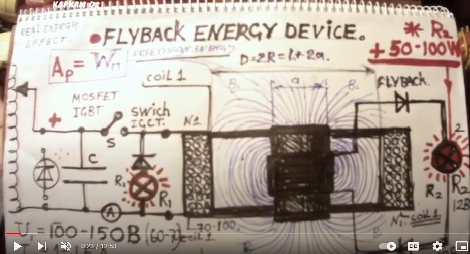
Andrey Melnichenko is another great inventor and has several patents on the effect he found. On his Utube channel he made countless videos to demonstrate the effect he found.
Chris has made several demonstrations to allow everyone to better understand the different effects of Andrey Melnichenko's research and I would like to make it a study and continuity of his thread.
When doing various searches on the web it is very rare to find those who have managed to make a replica of its effect.
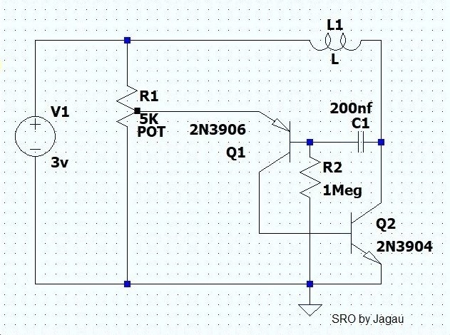
To study the phenomenon take the very simple diagram from the website of A. Melnichenko

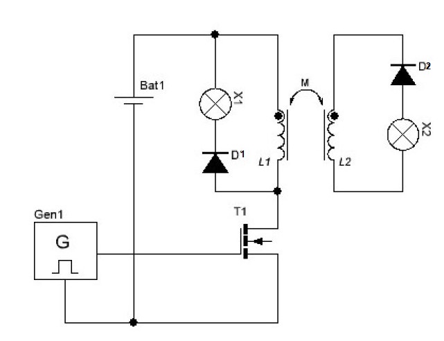
This schematic has two coils L1 and L2 in mutual connection and as can be noted the same phase polarity (dot). To understand what is happening in the coils, an analysis of the polarities is necessary.
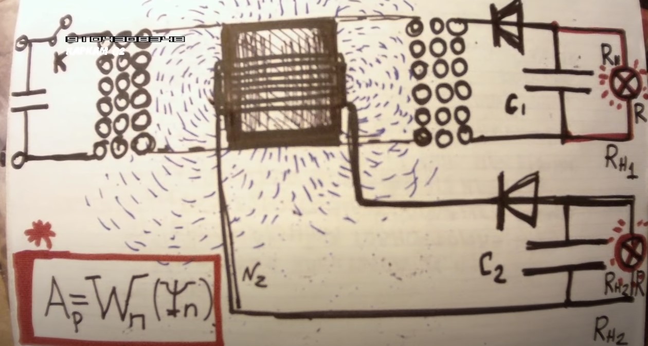
As Melnichenko himself explains there are two phases to take into consideration, the 1st magnetization and the 2nd demagnetization.
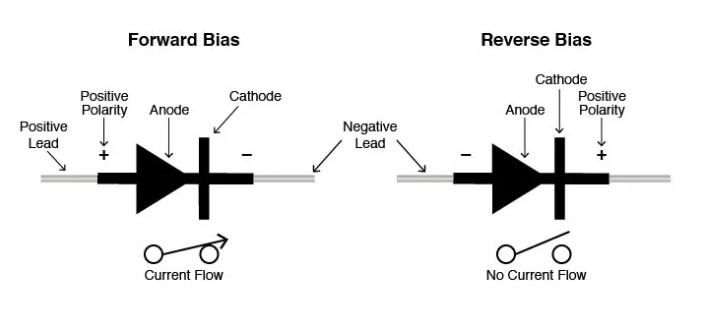
1 When magnetizing, T1 closes and L1 becomes negative on the bottom and positive on the top with the same phase polarities on L2. D1 and D2 being in reverse polarity then X1 and X2 do not light up.


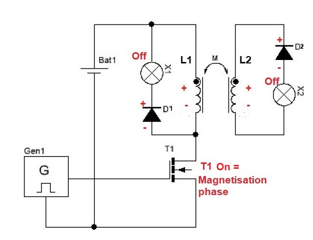
2 During demagnetization, T1 opens causing L1 and L2 to reverse polarity as shown in the following diagram:


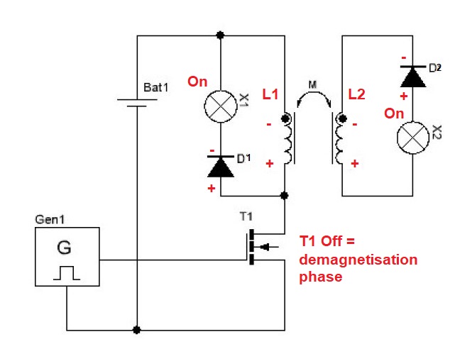
Since D1 and D2 are now forward biased then both diodes conduct so that X1 and X2 turn on.

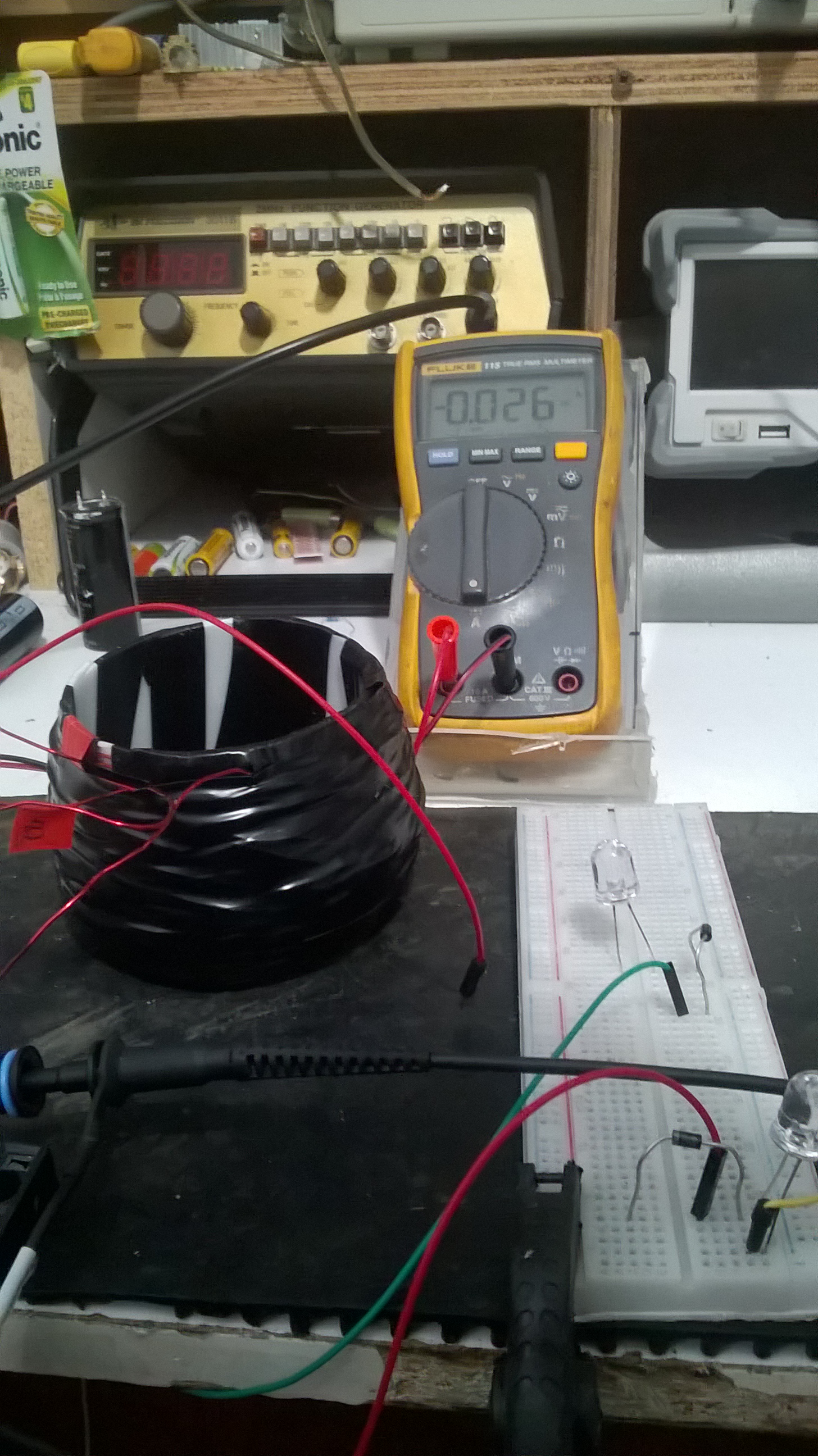
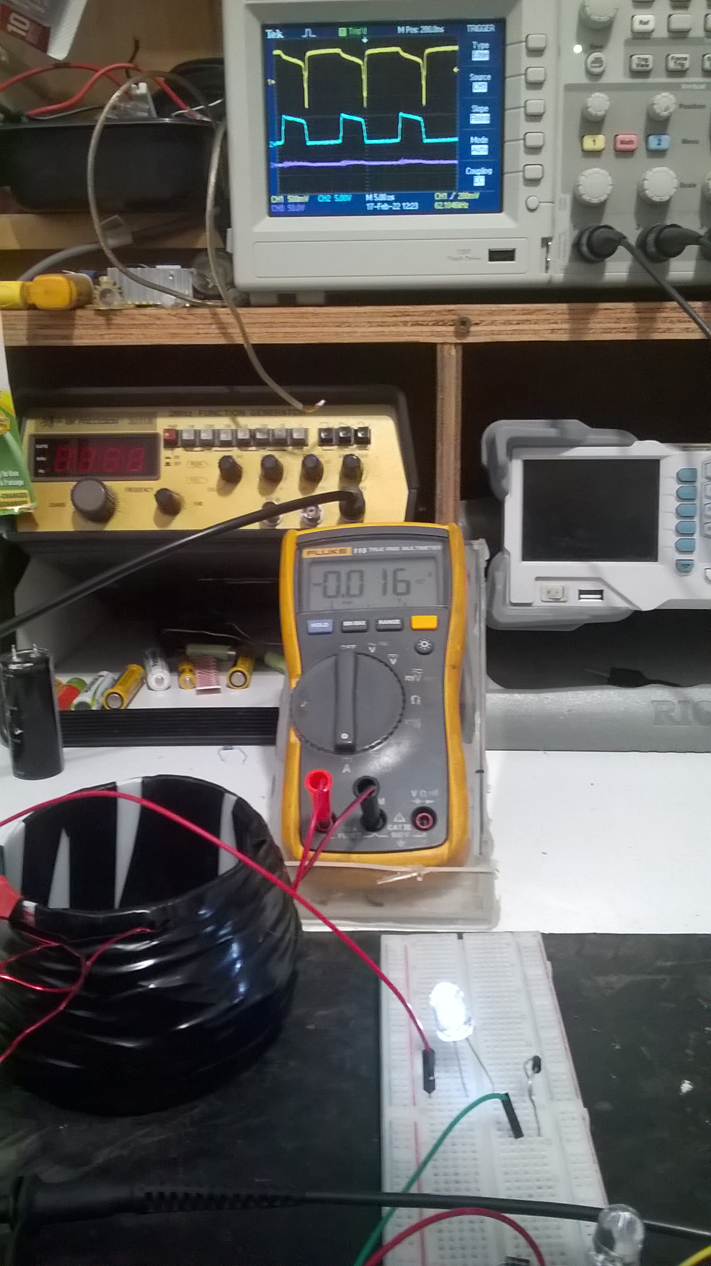
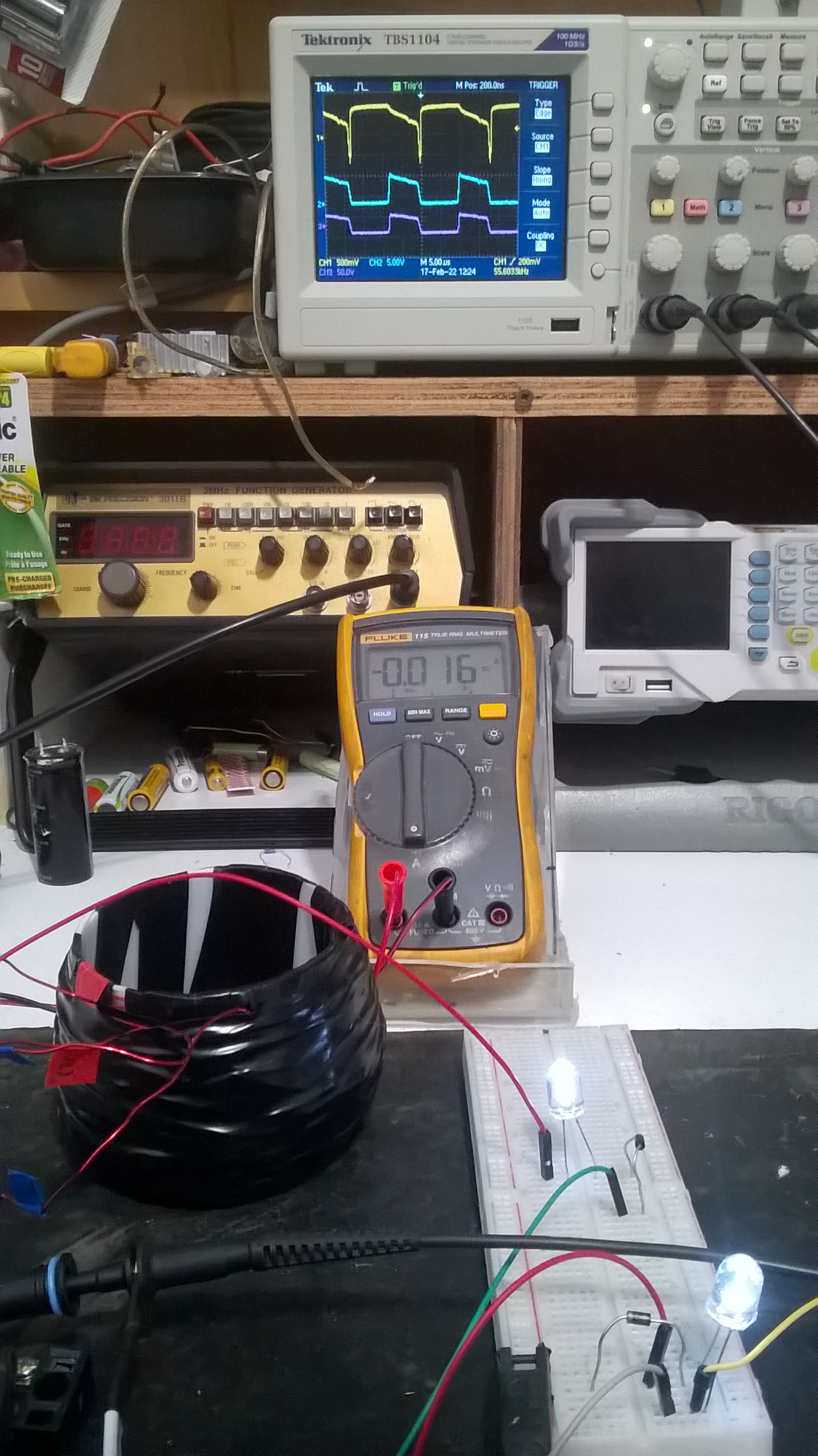
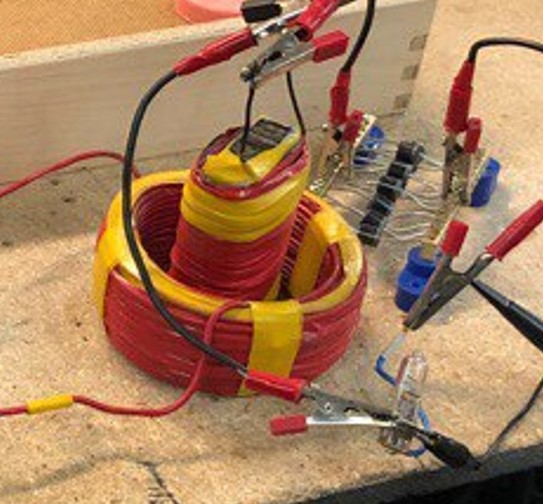
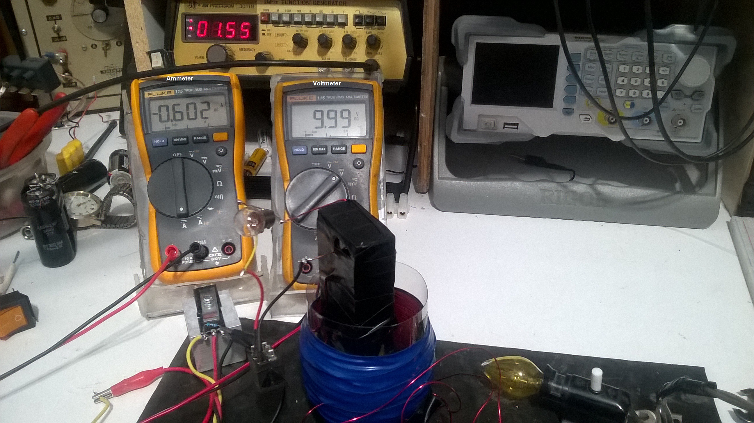
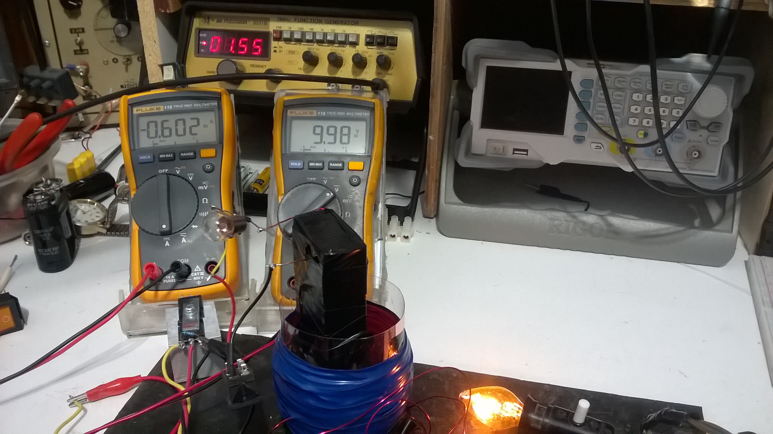
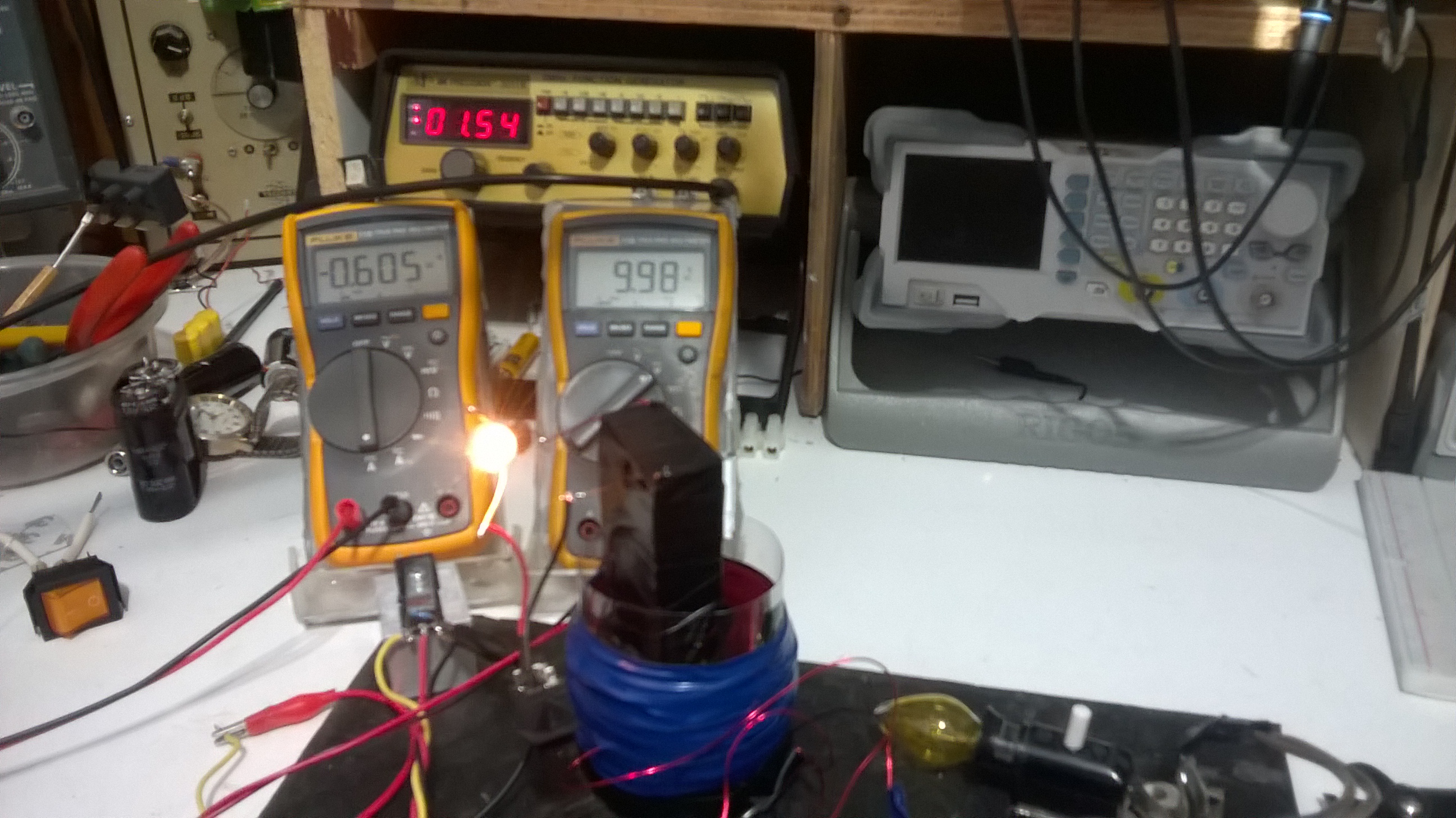
Practical experience will follow to demonstrate if this is indeed what is happening.

Jagau


Order By: Standard | Newest | Votes
Jagau posted this 15 February 2022

Just a little reminder for the operation of a diode, forward and reverse bias.

Jagau


  • Liked by
  • Augenblick
  • baerndorfer
Chris posted this 15 February 2022

My Friends,

This is an Excellent Thread!

I would like to inject a small snippet: The Source

In Symmetrical Electromagnetic Induction, we have a singular Input and a Singular Output, symmetry exists between these two Inductors, MMF is equal and opposite, Output is Input minus Losses, or Losses = Input - Output.

In an Asymmetrical System, we have multiple Sources!

Input Inductor, POCOne and POCTwo are all inputs to the System, and two are also Outputs all at the same time!

Think on this, because each Coil works with the other, to Push, Pull and Push again in the System. MMF = InputMMF + POCOneMMF + POCTwoMMF = POCTwoMMF. Or: 1 + -1 + 1 = 1.

So we have Force in the System, over and above the Input Symmetry that so many expect to see, it doesnot work that way!

You can say: Input Coil is POCOne's Source, POCOne is POCTwo's Source and POCTwo is the Input Coils Source.

This is why your Input Current comes down by a factor, as POCTwo's Current gets stronger, the Forward MMF reduces your Input Coil MMF from the Input Power Source!

So, to the Point, Diode Conduction, Forward Bias, is depends on what Source Created the Applied Voltage, so take a little time to see why there can be more than One Source in a System, an Asymmetrical System!

Best Wishes,

   Chris

  • Liked by
  • Jagau
  • Augenblick
Jagau posted this 16 February 2022

Exactly my friend very good suggestion, there will be several and surely an asymmetry of more than two coils and more than one source.
I am only at the beginning of the demonstration and we will see during the evolution of the study of the Melnichenko effect, that this is due to an asymmetric system, this is what we will discover together.
I'm going very slowly so that everyone understands well and this with examples that are easy to study and that others can replicate (at least I hope so) as the thread evolves.
I think we owe it to Andrey Melnichenko with all the efforts he makes to educate us.
Jagau

  • Liked by
  • Augenblick
Chris posted this 16 February 2022

Hey Jagau,

I agree, sorry!

Happy to assist, and experiment when you're ready 😉

Best Wishes,

   Chris

  • Liked by
  • Jagau
  • Augenblick
PutuGede posted this 17 February 2022

Hi Jagau,

Maybe  my note will speed up  this experiment  :

  1. Mosfet should have fall time <10 nS, Iam using Infineon 6r099c6, use original one.
  2. Use POC as L2, like what Wistiti does with his joule thief.
  3. Find best Freq & duty cycle while there is no load on L1 & L2
  4. Start with very low duty cycle, monitor on the mosfet drain, no load on L1 & L2 
  5. Adjust the load on L1 to find best result on L2 load.
  6. Switch diode direction on L2 to find minimum input power, exactly the same as Wistiti experiment.

Hopefully this note will help.

Best regards

Putu 

  • Liked by
  • Jagau
  • Augenblick
Jagau posted this 17 February 2022

Experiment no1 with the schematic here above;


On the first image I powered L1 with 2 X 1.5 V batteries and my oscillator circuit that you know. I placed an ammeter a on the negative of the 2 batteries in series in order to have an idea of ​​the consumption of this one. Both coils have 75 turns 3 inch radius without core (air core)


As you can notice in the first image the total consumption is 26 ma just to power the circuit at 3 volts DC when no load is connected i.e. Led1 off and Led2 off.


On the second image I connected Led1 as a load and the consumption went from 26 ma to 16ma, so at this moment a drop of 10 ma. You will notice channel 1 (yellow trace) connected to the base of Q2 on the SRO when the pulse collapses at OFF time the blue trace, connected to Led1 appears and led1 lights up.


At the third image, it starts to be more interesting, when I connect the Led2, the consumption does not increase it remains at 16ma. This is called energy which is normally wasted and recovered on Led 2


Andrey Melnicehnko with his basic circuit demonstrated how to recover this wasted energy but he did much more than that, it is in the sequel that it is even more interesting. As my friend Chris said, the second source that was thus created will serve us for something just as interesting.The demonstration here is with Leds later in a subsequent experiment we will be able to admire all of Melnichenko's work with incandescent lamps.

My SRO, autonomous oscillator


More to come

Jagau

  • Liked by
  • Augenblick
  • baerndorfer
Jagau posted this 17 February 2022

We wonder why the consumption drops when we connect a load (led)?


I would explain it this way:
when the load is connected to the negative half wave in the secondary winding (i.e. when the core is demagnetized), less energy is spent on its magnetization, as evidenced by the drop in the current consumed when load 1 and load 2 are connected.

So the load consumes energy in the absence of a pulse in the primary winding, and thus, the work is done only on the magnetization of the air core. (L2 help L1, imagine with  an iron core)


Andrey explains that with this basic circuit you can do it. But he did more than that.


Jagau

  • Liked by
  • Augenblick
Jagau posted this 19 February 2022

The design of the second circuit experiment of A. Melnichenko will be this one.
A photo of his set up,


with the circuit used, original circuit of Andrey Melnichenko

By using incandescent bulbs instead of LEDs

I will be able to better gauge the wattages that occur in this type of arrangement.

Jagau

  • Liked by
  • Augenblick
ISLab posted this 19 February 2022

Thank you Jagau for sharing and teaching with these very interesting experiments!

Can you share what is the frequency at which the SRO operates with these coils?

I'm still working on my current coils and will post shortly with details. But I have two questions that come as doubts even in my readings:

1. Is input current read through a digital ammeter reliable? What if there are narrow pulses of current drawn that it does not register? Can you check with oscilloscope on input current just in case?

2. When I get the current drop on adding a load, could it be that earlier (with no load) the current draw was higher as the secondary was shorted and was also drawing more current; and now that we added a load, the secondary draws less current and hence the primary also draws less? Can you check to ensure this is not the case?

Please don't misunderstand my intention here. I know there is OU here because this is the basis for the eternal torch. But when taking such readings, it would be useful to ensure that we eliminate all potential issues.

I myself am testing rigorously for such things before I post the results with my current coils.

Thank you again for this valuable sharing!

  • Liked by
  • Jagau
  • Augenblick
Jagau posted this 19 February 2022

Hey Islab
Thank you for your questions that I imagine everyone is wondering.


For your first question the frequency of SRO is Frequency 55.7 khz
At this frequency, especially if it is pulsed, the precision of a DDM is not there. At a maximum of 2 kHz the Fluke 115 has an accuracy of 2% whereas at 55 kHz we are far from accurate. Do not forget that the DDM is directly at the output of the batteries and not on the pulsed consumption of the LEDs.The oscilloscope is the ideal tool to measure accurately at these frequencies. As the experiment is only at its beginning, other experiments will come on precision. But with a DDM it only gives us a good idea of ​​an increase or decrease.
Imagine A. Melnichenko used an analog meter to get just an idea if there is an increase or a decrease. Some analog meters can also read up to 2 and even 3khz but they are very expensive and designed on request only.


For the second question which is the whole basis of the explanation of Andrey's experiences, I am just beginning to have an idea of ​​what is happening and a lot of questions still to be answered. But you will see in the following experiment with incandescent lamps and with frequencies close to 1.2 to 2.5 khz the responses with a DDM take on their full meaning. A. Melnichenko worked at these frequencies.


Unfortunately on the net there is not much replication of this experience, I am in research mode like you and the experience is still young. I suggest to all those who want to accompany me in this experience to come and replicate it with me, so that the experience will be more interesting for all.
Hope this answered
Jagau

Mimo posted this 19 February 2022

Hello all,


you can follow AndreÑ—'s posts here:


https://vk.com/id285085326 

and Youtube : https://www.youtube.com/channel/UCEtqI2EhN32Mvq7Wp5G9Vpg/videos

Mimo

  • Liked by
  • Jagau
  • Augenblick
Jagau posted this 19 February 2022

Yes thank you Mimo
I know his VK site well.
I am registered as one of his fans
Jagau

  • Liked by
  • Augenblick
  • Mimo
ISLab posted this 23 February 2022


Hope this answered

Yes, thank you Jagau!

I suggest to all those who want to accompany me in this experience to come and replicate it with me

I hope to do that once I finish my present explorations.

Looking forward to your further steps and explanations!


Brian posted this 24 February 2022

Jagau thankyou for sharing your experiments

You ask the question

So the load consumes energy in the absence of a pulse in the primary winding, and thus, the work is done only on the magnetization of the air core. (L2 help L1, imagine with  an iron core)

So I decided to try one of the cores I wound for the Eternal Flashlight.

Current draw with L1 and L2 unloaded was 13ma @3VDC

I then loaded L1 and current draw dropped to 10ma???

But Loading L1 and L2 increased current up to 22ma???

Why do we get these very different results between types of coils? I don't have that answer yet. Clearly I have more work to do understanding this.

I also seek to understand why you settled on the size air core you chose? Understandably a air core resonates at a higher frequency, but I need to investigate the effect of diameter of these. Why 3 inches and not 1 inch?

Thank you for sharing your experience Jagau and I look forward to the next lessons.

Kind Regards

Brian

  • Liked by
  • Jagau
  • Augenblick
raivope posted this 24 February 2022

Hi Jagau!

Interesting thread!

Yes, you need to test with incandescent bulbs for better amps, you need higher voltage, low resistance mosfet and right proportion of coils to be asymmetric.

If Melnichenko system works - I am sure it works on the same principle (saturation asymmetry) as I have seen a working device with a COP 1.7..2.1, running purely from the grid at 50hz. Kilowatt range and not a toy. I saw it and double-measured when I visited one inventor long ago.

But I want to make sure that you understand that there are different working principles of AU devices. Some start working even on low-freq and in a nonlinear range, some want fast transients (RF), wire length matches - those or more like RE devices. In RE devices you might need a ground and cannot connect the output directly to input.

But I am afraid that Melnichenko does a measurement error - because he measures only amps, which do remain constant, but there will be a phase shift, which is not recorded and actually it will not be AU. Althought his circuits do look professional and detailed.

I do not want to be pessimistic, I really do encourage you to continue testing. You may use magnet to give the iron a saturation bias, where it may enter also a decreasing permeability zone - might be interesting.

Any info of other replications or did his 75kW devices really work?

All the best,

Raivo

  • Liked by
  • Jagau
  • Augenblick
Jagau posted this 24 February 2022

Hi Brian
If you follow the first circuit well, the most important thing is the phasing of the coils.
When L2 is in demagnetization mode it does not consume anything, so the current at the output does not affect the current at the input, check the phasing you will have good results.
Glad to see you're not afraid to experiment and ask questions.

@Raviope
Andrey has 3 patents on what he discovered so after my first test it seems conclusive, yes with incandescent it requires more voltage and current than with Led. I have lowered the operating frequency to about 2khz, it will be easier to follow for everyone and also for measuring instruments such as DDMs and to have convincing readings.
For the measures he takes don't forget that he knows what he is doing. He has worked in electronic engineering in his country and by studying his videos you can see very well what he is talking about, trust him
Jagau

  • Liked by
  • Augenblick
  • Mimo
Brian posted this 25 February 2022

Thank you Jagau

yes you are correct - I have fixed the phasing.

Kind regards

Brian

  • Liked by
  • Jagau
  • Augenblick
baerndorfer posted this 25 February 2022


when i played around with Andrej M. circuit and 2 e-cores i got pretty good results very fast.

this is what i build..

on the left we can see the primary coil which is switched by mosfet and the trigger.

the secondary on the right has a POC coil as usual

now look at the thermal image and you know where the energy comes from..

regards!


  • Liked by
  • Jagau
  • Augenblick
Chris posted this 25 February 2022

Hey Baerndorfer,

Beautiful work My Friend!

This reminds me of the work of both Paul Raymond Jensen, and another Researcher, Harold Aspen.

Harolds work is almost exactly the same:


Harold had so much trouble from the Nutty Establishment, simply because the lack of basic understanding of the simple processes of Electrical Energy Generation!

Paul Raymond Jensen used a feed back winding on the center leg Coil, this gave a better end result, in the same configuration:


Your work always impresses me B!

Best Wishes,

   Chris

Jagau posted this 26 February 2022

Nice build Baerndorfer

Indeed the small gap, between the two cores, it looks like Andrey's assembly
Have you had time to take some power readings? It would be interesting to know.

Thanks for sharing

8 years ago, another had done well, with English subtitles.

Watch the schematic of the T2 you will notice something familiar, and yes it is a POC configuration,T1 is just a standard step down Xfo.


Jagau

  • Liked by
  • Augenblick
Jagau posted this 27 February 2022

The last video above is of Mykhaylo Balush he is a Ukrainian by birth.

These are people like us who want to live and I have a thought for them with everything they are going through right now. I myself have a lot of difficulty concentrating on my experiences at the moment, pretending that everything is fine is an understatement.  

Jagau

  • Liked by
  • Augenblick
Jagau posted this 01 March 2022

For the rest of the experiment I used an IGBT as a switch at the frequency of 1.55 Khz
I used 3coils for this experiment and 2 lamps. The one on the pole is 12 volts 3 watts and the yellow one on the right is 115 volts 3 watts.
The readings of the ammeter and voltmeter DDM will be more believable because in these frequencies they can measure more accurately.
On the first image;

Both lamps are off and we can see a consumption without any load of 6.01 watts


On the 2nd image the 2 lamps are lit with the same consumption, the two lamps are not lit at full power


You will notice that I used Andrey's configuration with 2 lamps and 3 coils, one coil of which is inserted in the open air core, there is no magnetic link between them. Even if one or the other of the two 3-watt incandescent bulbs is closed, the consumption remains the same.


It is all the same an interesting configuration to study it is as if other sources of tension seem to appear. The next ones will be on a resonant circuit.

Jagau

  • Liked by
  • Augenblick
  • Mimo
Brian posted this 02 March 2022

Hi Team

Thought it might be helpful to share a really simple build with great results styled on baerndorfer build.

I used a E Core, wound 1 meter as the primary and 4 meter as POC1 (CW) and POC2 (CCW) using Jagau SRO circuit.

Unloaded you note a current draw of 34mA (this is the same if I complete the transformer with a unwound core)

Then positioning the wound POC coils with a slight gap you can see the current draw decrease to 24mA while delivering about 5mA to the load LED

I have upscaled Jagau SRO circuit somewhat in another build using TIP31 and TIP32 for higher power and can deliver higher current to a larger load. But feel there is probably more tuning that can be done on the coil design. I welcome suggestions on how I might design these coil windings for better efficiency and possibly OU.

Kind Regards

Brian

  • Liked by
  • Jagau
  • Augenblick
Jagau posted this 02 March 2022

Nice demonstration Brian.
Indeed when Melnichenko discovered his effect, it was with an E core and a spacing like you did Brian and in this way he had a great success.

His first youtube setup, 5 years ago


Yes the SRO can be modified at will with more powerful BJT and with Mosfet too.

Bravo Brian


Jagau

  • Liked by
  • Augenblick
  • Mimo
Chris posted this 02 March 2022

Hey Brian,

One Meter of Wire will have a Resonant Wavelength around: 299,792,458.0 Hz or 299.792458 MHz, a very High Frequency for the average home Lab Equipment and difficult to achieve! Copper Wire is 96% of this Speed, due to latency of Copper.

In our Calculator, we have the ability to calculate this:


Resonance is important, this is where B, V and I are at maximum.

Energy Gains can be achieved when one finds Magnetic Resonance.

Best Wishes,

   Chris

  • Liked by
  • Jagau
  • Augenblick
Brian posted this 03 March 2022

Thanks Jagau and Chris

Please accept my apology for my knowledge in this area. I ask if you may provide a little more guidance?

From my experiments and research on the core I used, I feel that practically these are only suitable for frequencies in the Khz range not Mhz required for magnetic resonance with the short windings used. The calculator shows that in order to get into the range of around 300khz I will need a primary winding of around 1000 meters. Which is not practical. So I expect that tuning with a Cap is required. Taking 1 meter again as a example we calculate that a 0.0047 pF cap is required, which again is difficult to tune given that there is some internal capacitance in the coil also which is difficult to measure at these sizes.

This is showing for practical design a much longer primary is required and probably ferrite cores are not ideal. Air cores might be more practical? 

Which brings us back to Jagau's experiment with air cores.

Is this correct thinking or am I off track?

This experiment has prompted me to go back to the eternal flashlight builds and retest with a small air gap in the pot cores. I will report back on this on that thread.

Kind regards

Brian

  • Liked by
  • Jagau
  • Augenblick
Jagau posted this 03 March 2022

hey brian
The field of research is something very vast and captivating. In order to reproduce as faithfully as possible the experience of the Melnichenko effect, I proposed a first diagram with an Ecore. In order to understand the diagram I have with various biases trying to simply show what is going on.

Over time, it became apparent that the air core combination with a large condenser achieved the desired ends better. There is no saturation in an aircore like Don Smith did, so we don't have to worry about that detail. In addition, it has gone from 2 coils to 3 coils. The third coil having no magnetic relationship with the first two, as he so often describes.
One could then think of working on a POC and a parametric recovery of the voltages produced.

This will be the subject of the next experiments.


Jagau

  • Liked by
  • Augenblick
Brian posted this 03 March 2022

Thanks Jagau - I look forward to following these.

  • Liked by
  • Jagau
  • Augenblick
Chris posted this 03 March 2022

Hi Brian,

Hey thats why we are here! To Help!

The tickle under the chin can be in the Duty Cycle, as Energy is Gained in the Time Domain, and a very short narrow Duty Cycle can act as a High Frequency, when in point of fact the Frequency can be down in the 10's of Killohertz or less, and the Duty Cycle may be 10% or less!

We also have to remember, a Voltage is "Generated"!

This means, as a function of Faradays Law, Voltage is a product of the Magnetic Field changing in Time and the Turns.

In other words: EMF = -N dΦB / dt


This means, in a well designed machine, the Voltage is classically a function of Faradays Law. Resonance can be Specified by Design, pretty much.

The Value of B, the Magnetic Field Density, is an important aspect in any Electromagnetic Machine. Most of the machines shown have had very minimal Magnetic Fields!

Soon, we will have more, we are at the point now, where steps ahead are going to be very much further that we are now! Of course, surrounding ourselves by Genuine People should be our main priority for now, as a group we need status and reliability in the eye of the Main Stream!

We have much of this already, visits are at an all time high.

Closely observing the TOn, when the Coils are at Maximum Interaction and Opposition Starts, of the Partnered Output Coils, is where one can make massive steps forward! Most overlook this, even though I have shown this in the Thread: Some Coils Buck and some Coils DONT


Observing this TOn time, and what the Coils are doing at this time, and maximising this Effect, in other words, getting the Magnetic Field, the Voltage up as high as possible, within reason, should be the Goal! Energy Density is a product of the Amplitude of these Quantities!

POCOne and POCTwo can reach very High Amplitude for very little Energy Input! But only when Parameters are met!

Best Wishes,

   Chris

  • Liked by
  • Jagau
  • Augenblick
Jagau posted this 09 March 2022

Other pictures with


the 115 volt lamp only on


the 12volt lamp only lit

And power remains stable.

Jagau

  • Liked by
  • Augenblick
  • Shadow_
Jagau posted this 11 March 2022

Before continuing Andrey's experiment, I think it would be a good time to verify the non-additive law of magnetic waves. We will come back to it later according to the results found. I'm actually doing a separate thread so as not to overload this thread which will surely be appreciated by many.

Jagau

  • Liked by
  • Augenblick
scalarpotential posted this 15 March 2022

Hi all,

I see two coupled inductors that operate as flyback coils, the fields and voltages don't collapse instantly but slowly like a POC, they decay slowly through mutual inductance and currents, creating 2 regauged potentials with a working time longer than the duty cycle.

Is this a somewhat correct description of the circuit?

Ingenious if it works.

Cheers

  • Liked by
  • Augenblick
Jagau posted this 15 March 2022

Melnichenko's experiment is Nonlinear inductance energy generator composed of 3 coils.


The basic premise as well explain Andrey is:

During demagnetization (break, decrease in current in the coil on the first rod) on the second ferromagnetic capacitor ) a special removable winding (third coil) is set which connects to the load only during demagnetization (does not participate not to magnetization) ). Thus, all the energy of the deposited secondary magnetic field can be transformed into additional useful energy per cycle.

Jagau

  • Liked by
  • Augenblick
Jagau posted this 15 March 2022


Before going any further here is what I am trying to prove in another thread

The wave energy is determined by the wave amplitude.

On thread additive or not

Jagau


  • Liked by
  • Augenblick
Chris posted this 15 March 2022

Hey Guys,

I agree with Jagau!

I would like to add, there are two phases, and not just the one:

  1. Magnetisation Phase. ( Regauge )
  2. Demagnetisation Phase. ( Work Region )


There must be a Magnetic Resonance, on the Magnetisation Phase, so as to achieve Maximum Voltage Potential, for a Minimum Input Power! Which requires some work to find this optimum Frequency and Duty Cycle, for a given Input Power.

On the Demagnetisation Phase, the Coils will release Energy, your Input is off, at their natural rate, depending on the Magnetic Fields Energy Density, which oppose. Bucking Magnetic Fields!

Magnetic Fields Buck, for both Magnetisation and Demagnetisation Phases.

Magnetic Resonance has nothing to do with Core or anything else, other than the Coils Natural Parameters. In other words; there is NO Magic here, its simply Magnetics!

The process becomes an Asymmetrical, Sawtooth Waveform, which we have shown many times on this forum! Energy is gained in the Time Domain!


I hope this helps?

Best Wishes,

   Chris 

P.S: Standing Wave Mechanics require specific configurations for 2B and or 2E, I have not figured out how to achieve 2B and 2E at the same time, B must be 0 to achieve 2E.

  • Liked by
  • Jagau
  • Augenblick
scalarpotential posted this 16 March 2022

Please look at 17:00, it is the same as the simple Melnichenko design, but it has a separate primary magnetizing coil:

  • Liked by
  • Jagau
  • Augenblick
raivope posted this 16 March 2022

Hi,

I have a theory that a bit differs.

If you have the ordinary flyback system it is not OU. Its requirement is to have coils further of each other, to create 2 superpositions in fields i.e. 2 dipoles, especially when they are opposing. NS and NS. But during the collapse you will have fluxes glued together - a single dipole NNSS. Magnetic material has a permeability (thus inductance) increase as well and this is where gains come from.

If this is not that simple then maybe there is needed some RF reflection magic to shake it that depends on wire length where the radiation does the dipole splitting-joining that happens by design. Sometimes external Tesla Transformer is used to inject RF into it. Did Akula use copper sheets in a coil that got RF from transients?

Thus I do not fully agree with that:

Magnetic Fields Buck, for both Magnetisation and Demagnetisation Phases.

During magnetisation (like Melnichenko) - even when there is no load - the core material has eddy currents that create opposition. POC has a diode short to do that. But during the demagnetisation - the idea is to have most of the core covered with coils to take energy out from everywhere. Exactly like Melnichenko does - he takes it from the primary and secondary creating one dipole.

Some say that you can collect energy from BEMF - its free? Not at all - if you take out from any part the energy it reduces the field bubble. Thing is that you get free when permeability is parametrically increased and that is done where you put collection coils.

I have seen a working system (transformer) long ago 50hz and sinewave (from grid). No RF. Worked when asymmetric load was put on it and went into saturation.

Does POC work on the different principle?

First question is - does POC work with sinewaves? Or does it require fast transient to generate a wave that reflects? If so - RF is a requirement.

Did VTA work on 60hz sinewave? Was there any magnetic field hack NS NS to NNSS?

What happens in Don Smith generator, where coils are wrapped (OPPOSINGLY) on stator magnets: N//S | N\\S?
Is there the same dipole thing happening? NS NS to NNSS?
Is the same dipole-splitting-joining thing happening in DS secondary (double mirrored coils) during modulation?

Just some thoughts...

Raivo

  • Liked by
  • Jagau
  • Augenblick
Jagau posted this 16 March 2022

Hi

Very good reflection Raviope, indeed A. Melnitchenko do not uset an ordinary flyback and it is based on the principle of superposition of the fields.
The gain comes from the parametric effect of the inductors involved and the increased energy density thus produced and the fields generated.
As you may have noticed in the experiment I did, the primary is an air core and the secondary is wound on a ferromagnetic core. As you probably know ferromagnetic materials have what is called zero inductive impedance (resistance) so no eddy current here. During demagnetisation, this is where all the work happens with proper phasing of the diodes acting as the key.


Jagau

  • Liked by
  • Augenblick
Chris posted this 16 March 2022

Hi Raivo,

You are very far ahead in this field!

I will study your post in further detail, but on first read, I believe we are on the same page, only we see a slightly different view of the same things.

If you have the ordinary flyback system it is not OU.


This is true and must be realised by all readers! The Bedini SG was never an AU Machine by itself! As are all machines that follow this same basic concept! Flyback is NOT AU! Raivo is Correct!

Yes, the VTA worked on Sine Waves as do POC, but only in a specific configuration. I will cover this in more detail at a later date, some I have already covered.

DC Pulsing is, I believe easier to understand.

Regarding RF, this is an excellent point! There is what could be considered an RF Component in DC Pulsed POC but not so in AC POC, but primarilly due to the Mosfet Switching Characteristics, and not so much due to the Coils themselves, however, the Magnetic Resonance component may fall into the RF Domain depending on the Coils Geometry and Design that the individual chooses.

This may be true even if your frequency is not in the RF Domain! This is a broard topic and requires much more detail to cover properly.

Partnered Output Coils are the exact same principle as the Conventional Electric Generator, we have only added Asymmetry to a purely Symmetrical System!

The Electron's in each Copper Coil go through the very same processes in POC as they do in a Conventional Electric "Generator"! The Copper Cu Atom each having 29 Electrons, Each can be Freeed and Accelerated, depending on Magnetic Field Strength of each Opposing Field!

Magnetomotive Force Frees the Electron and Accelerates it, giving the Electron a Velocity, required for Current, and the Magnetomotive Force to do this is largely Free, due to the applied Asymmetry!

I do wish people would listen, as we have said here many times, Flyback is NOT the principle here!

Best Wishes,

   Chris

  • Liked by
  • Jagau
  • Augenblick
Melendor posted this 16 March 2022

Hello Chris.
Lots of Information here for all the people that hear what you say.

I would like to add, there are two phases, and not just the one:

  1. Magnetisation Phase. ( Regauge )
  2. Demagnetisation Phase. ( Work Region )


There must be a Magnetic Resonance, on the Magnetisation Phase, so as to achieve Maximum Voltage Potential, for a Minimum Input Power! Which requires some work to find this optimum Frequency and Duty Cycle, for a given Input Power.

On the Demagnetisation Phase, the Coils will release Energy, your Input is off, at their natural rate, depending on the Magnetic Fields Energy Density, which oppose. Bucking Magnetic Fields!

Magnetic Fields Buck, for both Magnetisation and Demagnetisation Phases.


The process becomes an Asymmetrical, Sawtooth Waveform, which we have shown many times on this forum! Energy is gained in the Time Domain!

Gold Information here guys.

I always blocked POC1 in the Magnetization phase , so that no current flows when the DC power supply is ON.
However from what you have stated above , current must flow both when Mosfet is ON and OFF.

Will try the experiment with the new information as soon as posible.

Thank you !!!

~~~Melendor the Wizard

  • Liked by
  • Jagau
  • Augenblick
Jagau posted this 16 March 2022

Even if Andrey calls it a flyback energy device it's much more than that, if it was as simple as that many would have been able to copy it a long time ago.


To avoid repeating myself, read the entire thread to better understand the effect in order to replicate.


Jagau

  • Liked by
  • Augenblick
Chris posted this 16 March 2022

My Friends,

This thread is an excellent example of why we are the best, most advanced Forum in the World, in the Energy Field!

We put others to shame, those gurus cant even figure out the most basic things!

I am so proud of you all! This is awesome!

Best Wishes,

   Chris

  • Liked by
  • Jagau
  • Augenblick
scalarpotential posted this 17 March 2022


Magnetomotive Force Frees the Electron and Accelerates it, giving the Electron a Velocity, required for Current, and the Magnetomotive Force to do this is largely Free, due to the applied Asymmetry!

True, this is according to Faraday's law. But to have a current, the  loop must be closed and the current must flow through the  EMF source, like a battery or in this case the coil. Or else an electret could sustain a current, but no current can flow through it.

  • Liked by
  • Augenblick
baerndorfer posted this 17 March 2022


the video shows what happens, when a sharp pulse (1,5kV/50ns) goes through the powercoil.

https://gab.com/tankcircuit/posts/107973111062784772


the flames happen, where the maximum compression takes place - this is what i think...

if someone can make this video appear within this post - would be great

always a pleasure to read your content.

regards


EDIT by Chris, Video Added as requested 😉

  • Liked by
  • Jagau
  • Augenblick
Jagau posted this 17 March 2022

Hi Baerndorfer


It seems that you have 5 and maybe even 6 coils including the red circle in your setup,

tell me a little about it?

Jagau

  • Liked by
  • Augenblick
baerndorfer posted this 17 March 2022

hi jagau,

on the left side centered you can see the powercoil (where the flames happen).

on top of left core is the triggercoil.

second e-core on right side - here is the POC coil
the red ring is another output - i use it for powering the fan to have some cooling.

regards!

  • Liked by
  • Jagau
  • Augenblick
Chris posted this 17 March 2022

Hey Guys,

This is great work!

Baerndorfer is a superb, first class experimenter! Neat tidy professional Builds!

I would like to urge all here to think about the Magnetic Field in Terms of Energy Density

Coils, or Inductors have the Parameters:

  • Current I
  • Turns N
  • Length l
  • Permeability μ0
  • Relative Permeability μr


Which define's the Magnetic Field in both Density B, and Strength H, which is related to M.M.F via a Length Component.

Energy Density has an Area Component, and is normally in Joules per Meter Cubed: J/m3

M.M.F, or the Magnetic Field Strength H, is also Current Density and this is Joules per Meter Squared: J/m2.

This means we have a direct relationship between Energy, M.M.F and Area! So the more we increase Area, with the same turns, and Current, with shorter Coils, as Baerndorfer has shown here, the more Energy per unit volume we have access to.

This is for Scaling our Machines, which will be important for our future!

Its all in the Understanding!

Best Wishes,

   Chris

  • Liked by
  • Jagau
  • Augenblick
Jagau posted this 18 March 2022

Hi Baern
If I can afford a little advice to avoid sparks and flames. melnichenko used cables with very thick insulation such as RW90 or TFF, with 1kv insulation and more, maybe that would solve your problem.


Thanks for the feedback, nice job.


Jagau

  • Liked by
  • Augenblick
Jagau posted this 21 March 2022

In order to evaluate the technical performance of the circuit, I am building a power performance evaluation tool. In Brief: As power equals voltage squared divided by R so


the magnetic generation index = ((Vdem^2)/10000) / ((Vmag^2)/10000)

i will used a 10K resistor in parallel with a 22uf capacitor

the demagnetizing (V demag) voltage squared on an R of 10K divided by the Magnetising Voltage (V mag) over a 10K
This is the same technique that N.Zaev and JL Naudin used to measure the power delivered on a circuit

 Jagau

  • Liked by
  • Augenblick
Jagau posted this 22 March 2022

Hi all

Melnichenko coils are a very interesting subject to study.

 Demagnetisation over magnetisation, power coefficient we obtain 27.77, the result is convincing.

Jl Naudin had reached 13.7 with his 2SGEN and N. Zaev 16.3with nanoperm 81

you could read all details here with N. Zaev pdf    http://jnaudin.free.fr/2SGen/html/s2genep7en.htm

P.S. Comment from Vladimir Utkin: The load must be chosen so as to get the maximum amount of power flowing into it. Very low loads and very high loads will both have close to zero energy flowing in them.


Jagau

  • Liked by
  • Augenblick
  • Mimo

Topic Is Locked

We're Light Years Ahead!
Members Online:
What is a Scalar:

In physics, scalars are physical quantities that are unaffected by changes to a vector space basis. Scalars are often accompanied by units of measurement, as in "10 cm". Examples of scalar quantities are mass, distance, charge, volume, time, speed, and the magnitude of physical vectors in general.

You need to forget the Non-Sense that some spout with out knowing the actual Definition of the word Scalar! Some people talk absolute Bull Sh*t!

The pressure P in the formula P = pgh, pgh is a scalar that tells you the amount of this squashing force per unit area in a fluid.

A Scalar, having both direction and magnitude, can be anything! The Magnetic Field, a Charge moving, yet some Numb Nuts think it means Magic Science!

Message from God:

Hello my children. This is Yahweh, the one true Lord. You have found creation's secret. Now share it peacefully with the world.

Ref: Message from God written inside the Human Genome

God be in my head, and in my thinking.

God be in my eyes, and in my looking.

God be in my mouth, and in my speaking.

Oh, God be in my heart, and in my understanding.

Your Support:

More than anything else, your contributions to this forum are most important! We are trying to actively get all visitors involved, but we do only have a few main contributors, which are very much appreciated! If you would like to see more pages with more detailed experiments and answers, perhaps a contribution of another type maybe possible:

PayPal De-Platformed me!

They REFUSE to tell me why!

We now use Wise!

Donate
Use E-Mail: Chris at aboveunity.com

The content I am sharing is not only unique, but is changing the world as we know it! Please Support Us!

Thank You So Much!

Weeks High Earners:
The great Nikola Tesla:

Ere many generations pass, our machinery will be driven by a power obtainable at any point of the universe. This idea is not novel. Men have been led to it long ago by instinct or reason. It has been expressed in many ways, and in many places, in the history of old and new. We find it in the delightful myth of Antheus, who drives power from the earth; we find it among the subtle speculations of one of your splendid mathematicians, and in many hints and statements of thinkers of the present time. Throughout space there is energy. Is this energy static or kinetic? If static, our hopes are in vain; if kinetic - and this we know it is for certain - then it is a mere question of time when men will succeed in attaching their machinery to the very wheelwork of nature.

Experiments With Alternate Currents Of High Potential And High Frequency (February 1892).

Close