Jagau
posted this
15 February 2022
- Last edited 18 December 2022
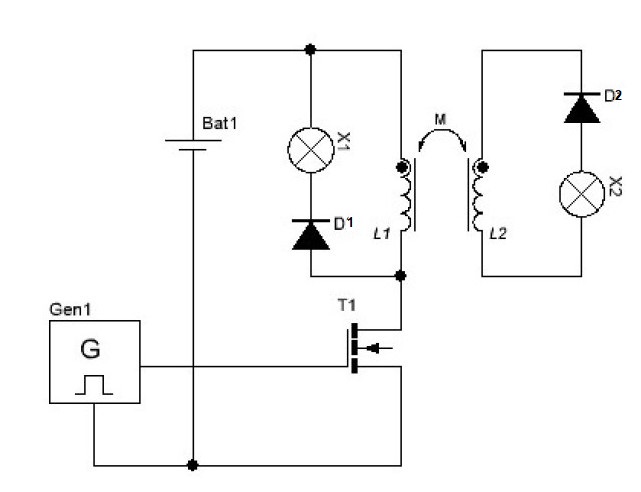
Andrey Melnichenko is another great inventor and has several patents on the effect he found. On his Utube channel he made countless videos to demonstrate the effect he found. Chris has made several demonstrations to allow everyone to better understand the different effects of Andrey Melnichenko's research and I would like to make it a study and continuity of his thread. When doing various searches on the web it is very rare to find those who have managed to make a replica of its effect. To study the phenomenon take the very simple diagram from the website of A. Melnichenko
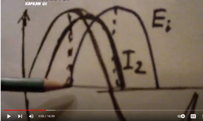
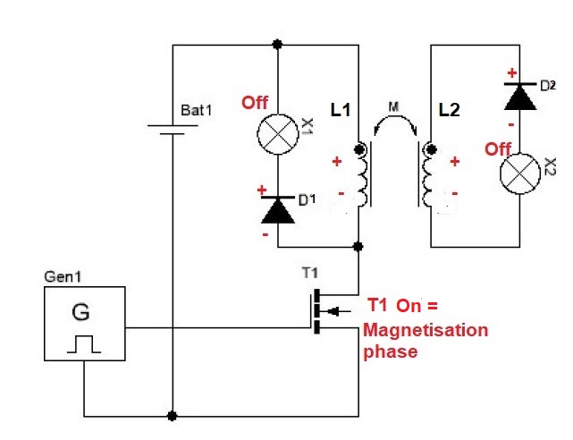
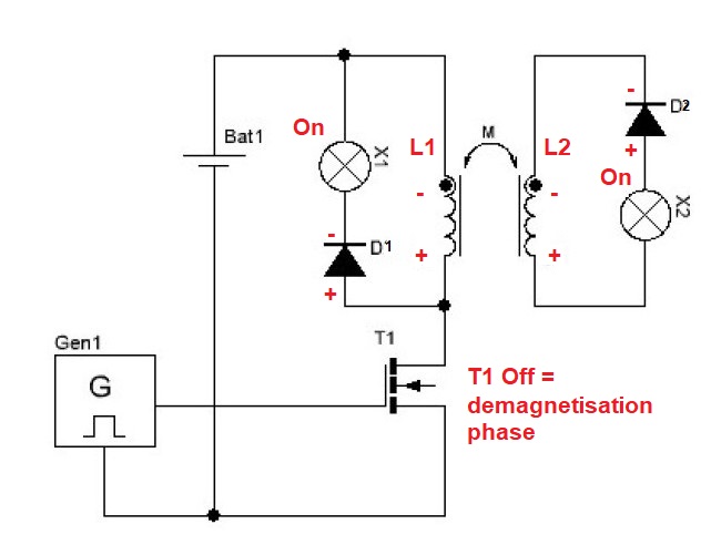
This schematic has two coils L1 and L2 in mutual connection and as can be noted the same phase polarity (dot). To understand what is happening in the coils, an analysis of the polarities is necessary. As Melnichenko himself explains there are two phases to take into consideration, the 1st magnetization and the 2nd demagnetization. 1 When magnetizing, T1 closes and L1 becomes negative on the bottom and positive on the top with the same phase polarities on L2. D1 and D2 being in reverse polarity then X1 and X2 do not light up.
2 During demagnetization, T1 opens causing L1 and L2 to reverse polarity as shown in the following diagram:
Since D1 and D2 are now forward biased then both diodes conduct so that X1 and X2 turn on.
Practical experience will follow to demonstrate if this is indeed what is happening.
Chris
posted this
07 November 2022
- Last edited 08 November 2022
Hi Thaelin,
The Input Bus, both Positive and Negative, are very important factors in the actual Machine Operation!
Many times we have covered that there is Energy being sent back, from the DUT/MUT back to our Input, which reduces the Input Power Required to Operate the Machine!
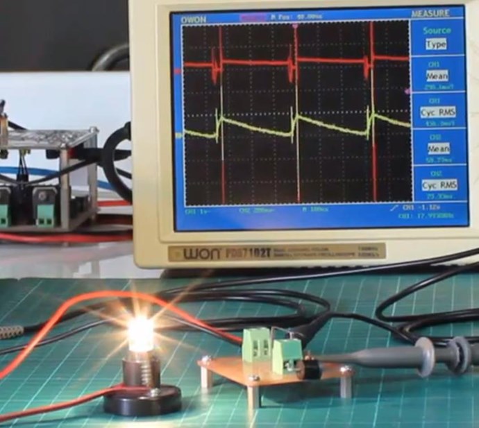
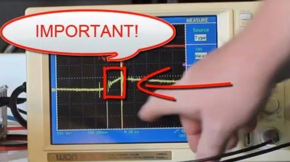
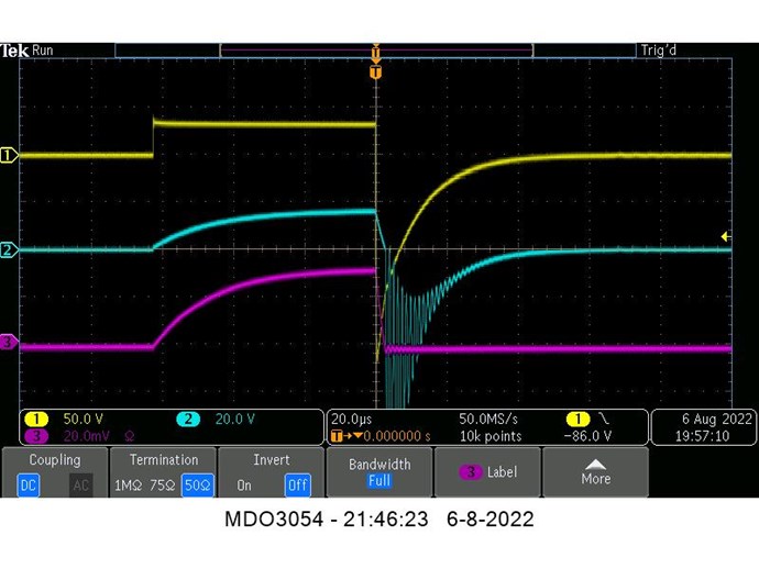
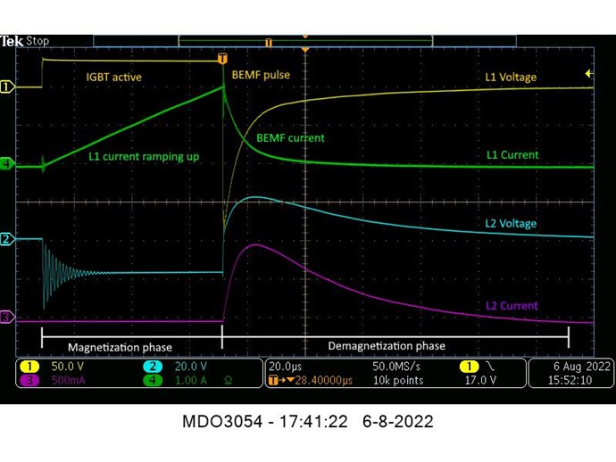
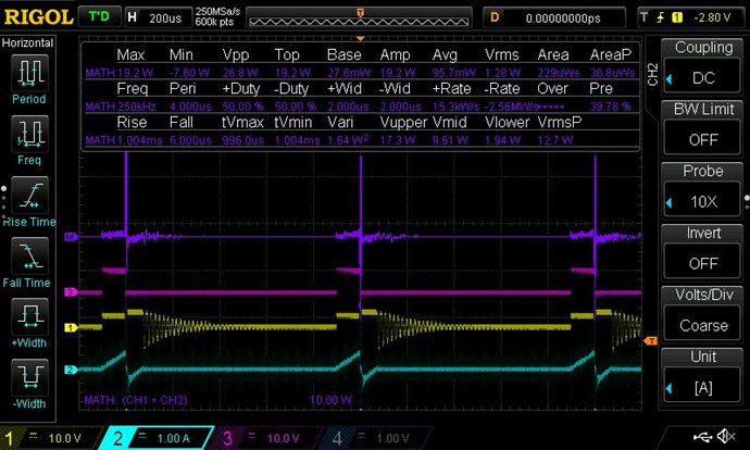
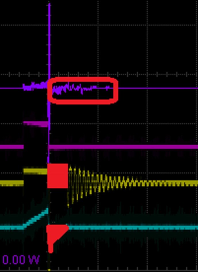
Here is an example:
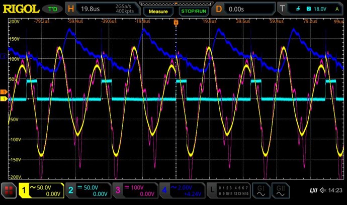
Where:
Purple Trace is the Math, showing Positive and Negative Power.
Pink Trace is the Gate Signal to the Mosfet.
Yellow is the Input Voltage.
Teal Trace is the Input Current, both Positive and Negative.
I must apologise, I have better examples of this, but do not wish to confuse everyone. This example is sufficient to show what I am talking about.
Again, marked in Red, Positive Voltage and Negative Current, you have Negative Power. Not Negative Energy, Negative Power, I hope people do not confuse this as I believe people have in the past.
I hope this helps others when doing experiments, knowing what to look for is very important!
Remember: This is the very reason you can NOT Use RMS Measurements on the Input! See Measurements Thread and see the above Figures:
Its not a new phenomena! Its actually VERY well known, Reactive Power is the very same phenomena, in the Time Domain!
Any and ALL Electrical Engineers should be very well aware of this and should be looking for it when taking any Measurement of any kind!
However, it is very conveniently Ignored, entirely, by all of the people trying to disprove what we have done! There is an active effort to show, at any cost, no matter how totally ridiculous, that these machines do not operate as we consistently show! Of course, its a Troll Tactic to lie and mislead the Public on such things so they don't see the truth! The truth that we are Consistently showing!
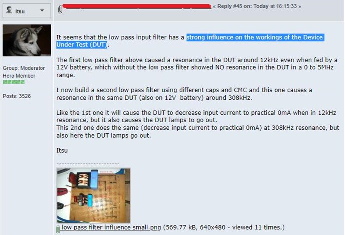
It seems we have another confirmation, of the Other Forums Measurement Practice being totally Un-Satisfactory for Accurate Measurements on a Running Machine:
The practice of insisting on Filtering a Main Buss, that affects the actual Operation of the Machine Under Test, or Device Under Test is BAD Measurement Practice and should NOT be done!
We now have confirmation, from Itsu, that was insisting on this Filter in the First Place, to make Bad Measurements, that this is now in fact the case!
I believe I have been telling others that this is NOT a good idea and is Bad Measurement Practice for some time now! Skimming through this thread will show you!
Remember, some of these people have been telling you for decades that DUT was a "Measurement Error" - Mostly Fake and False Information!
My Friends, this is why we are Light Years Ahead of the Other Forums!
Filtering out this phenomena is about as un-wise as anyone could get!
This is why we are Light Years Ahead of the Other Forums!
Chris
posted this
07 November 2022
- Last edited 08 November 2022
My Friends,
It seems we have another confirmation, of the Other Forums Measurement Practice being totally Un-Satisfactory for Accurate Measurements on a Running Machine:
The practice of insisting on Filtering a Main Buss, that affects the actual Operation of the Machine Under Test, or Device Under Test is BAD Measurement Practice and should NOT be done!
We now have confirmation, from Itsu, that was insisting on this Filter in the First Place, to make Bad Measurements, that this is now in fact the case!
I believe I have been telling others that this is NOT a good idea and is Bad Measurement Practice for some time now! Skimming through this thread will show you!
Remember, some of these people have been telling you for decades that DUT was a "Measurement Error" - Mostly Fake and False Information!
My Friends, this is why we are Light Years Ahead of the Other Forums!
I am ready to wind up the coils. Will use the rods I have for now and order ferrite from a local source here. I am a bit unsure of the turns count tho. I have a 4" form and 3 layers on it with 50 turns is only 2.7" . Is 50 enough or should I go more and double that for the inside coil?
scalarpotential
posted this
07 September 2022
- Last edited 07 September 2022
Jagau, this patent you're sharing is gold! Many thanks.
It closely explains how Chris' system is working, and what he has been telling all along but in less technical terminology. Phase-conjugate :
In operation, the system causes the split-flux transformer (SFT) to function as a pumped phase conjugate mirror (PPCM), which transforms conjugated electromagnetic (EM) energy to real EM energy. Very high transformer efficiencies have been realized with this technology. The PPCM occurs by splitting the flux equally between the two transformer cores. The two cores include secondary output coils wrapped around each core and wired in Such a way that the resulting magnetomotive forces oppose one another. This is a special bifilar output coil configuration, which has a benefit of greatly lowering the output impedance of the coils. The output coils may be wired in series or in parallel In addition to lowering the output impedance of the coils, little power is reflected back to the primary due to the mutual coupling of the coils. Therefore, power delivered to the primary coil is highly conserved and not wasted on impedance. Nuclear non-recoil action emits both real EM wave and its phase-conjugated replica EM wave. While the real EM wave is a time-forward wave, its phase-conjugated replica wave is time-reversed. The phase-conjugated time-reversed wave is present everywhere in the universe as negative energy and is utilized and transformed by the PPCM as real EM energy.
I think POWER FROM MAGNETISM HAROLD ASPDEN on hyiq may help to improve understanding of the Melnichenko setup. At the surface it's a dual flyback, the trick must lie in the gap and material (I may be wrong).
Jagau
posted this
06 September 2022
- Last edited 06 September 2022
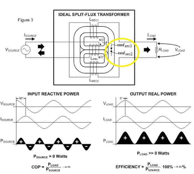
If we take a good look at the output configuration of Alek's SFT you will notice that the two output coils are in partnership configuration. Look in the yellow circle.
What Chris always said. Although others don't speak highly of his measurements, I find them to be correct. It's because he's a little ahead of the others and they have trouble understanding what he's saying, so they try to contradict him.
Jagau
posted this
05 September 2022
- Last edited 05 September 2022
Hi all
For those who want to understand it, even Bill Alek EE in Magnetic Flux Transformer patent US9620280B2, does the same calculation as me when calculating the average power in an inductor Pavg = almost 0 watt with some very minimal losses.
An inductor does not consume a watt same for capacitor.
The energy (joule) stored in an inductor momentarily can be calculated, the voltage (V) BEMF as well as the current (I) peak. But at no time the power in watt, because it is almost entirely returned to the source or as in Melnichenko it is used to light the first lamp, then it becomes the consumption of this first lamp which otherwise would have been returned to the source.
The meters measure the positive energy supplied to the source only.
Jagau
posted this
05 September 2022
- Last edited 05 September 2022
Hi all
In the current project here, on the primary side the pulse on the primary (air core) produces negative energy as predicted by Lenz's law. The energy thus stored in the inductor produces this negative electricity and is almost entirely recovered by lighting the first lamp. In addition, the air core is not magnetically linked to the other two ferromagnetic cores, which pick up the air core's magnetic fields for free with almost no magnetic link.
This is the first principle of the Melnichenko effect and it is called the principle of field separation. It is essential to fully understand this basic principle before going any further.
Again, Measurements should always be taken as close as possible to the Device Under Test WITHOUT Adding Unnecessary Components!
This is VERY very Bad Measurement Practice!
Itsu is basing his experiment around the PBE, or Power Balance Equation: PIn = POut, which does not hold when Power is Generated! Excess Charge is separated and Accelerated!
5.1.3 Power balance mode control (PBMC)
In the PBMC, the difference between the calculated inductor current iL* and the detected inductor current iL is added to the output signal of the voltage compensator. The responsiveness of the output voltage is determined by the crossover frequency in the open loop transfer function. Therefore, the change in the inductor current’s reference value (calculated inductor current iL*) is much slower than the change in the detected inductor current iL. Therefore, if the reference value of the inductor current is regarded approximately as the DC value in the steady state, it is almost equivalent to the configuration of the CMC.
REF: https://www.intechopen.com/chapters/64980
As Chris has already discussed, this power can be positive as well as negative.
I should also note, as we have stated already, Itsu has not yet seen ANY Negative Power! in his current experiments We have shown exactly what we are talking about, but Itsu has not seen a Whisker! What is Itsu Doing???
This means several things:
Input Power can not be reduced by a factor of Magnitude due to this Negative Power going back to the Input!
Itsu still does not have the Device correctly Built!
Itsu has not stopped to actually try to understand Energy and how Coils can have multiple Interactions with each other all at the same time.
Remember we have shown this:
Where:
Purple Trace is the Math, showing Positive and Negative Power.
Pink Trace is the Gate Signal to the Mosfet.
Yellow is the Input Voltage.
Teal Trace is the Input Current, both Positive and Negative.
Remember: This is the very reason you can NOT Use RMS Measurements on the Input! See Measurements Thread and see the above Figures:
So, we have shown you how to do this, and it seems, the Gurus still cant even get a simple machine to remotely look like its going to do what it should!
Yet they shove FASLY Represented Figures down your throat, showing you it does not work... Hmmm Yeah, I see what they are trying to do! Its going to fail, like it always does!
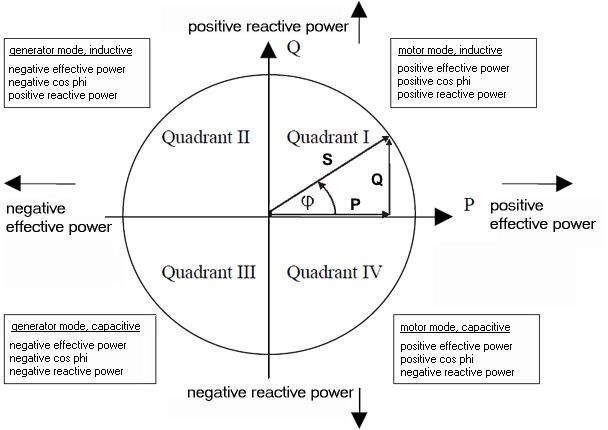
The Four Quadrant Power Flow, Argand Diagram:
We have already proven they are wrong and have not correctly represented the Device Under Test, this is what we have seen for Decades now! There is no Time or Room
I dont know if Jagau is still helping Itsu, but I hope Itsu does not waste Jagaus Time!
Learn about Negative Power, it will save you Decades of Head Aches!
Chris
posted this
01 September 2022
- Last edited 02 September 2022
Jagau, Baerndorfer,
You guy's Rock! You're awesome!
@All Readers trying to catch Up, look for Key Words and focus your Attention on the Key Words and what's actually being said in this Thread! Baerndorfer is correct, once one has a slight understanding, it makes perfect sense!
Jagau is also 100% Correct, but if I may add, its about Separating Charge and Accelerating Charge in an Asymmetrical fashion, at no cost on your Input side, this we have done!
All Electromagnetic Machines are Symmetrical Today! A Transformer, its Symmetrical! An Electric "Generator", its also Symmetrical! This means all Output, you must Input, in the form of, Mechanical Force or Torque, on a "Generator's" Input, which is Equal to what you get on the Output, Electrically, minus Losses! That's why Science tries to terribly explain Mechanical Force is Transformed to Electrical Force, or E.M.F. The WORST and possibly MOST INCORRECT Statement Science has ever made! In the case of a Transformer, the Force is M.M.F, which Negatively effects your input, and as a result your Input Current goes up as you add more load to the Output through Impedance on the Coils being Reduced! This means, always there will be a relationship of: Output = Input minus Losses! Always a Below Unity Machine! Never Above Unity!
We have introduced Asymmetrical Electromagnetic Induction, where all Force in the Machine does not ever Negatively effect your Input, so the Symmetrical Equation: Output = Input minus Losses does not apply here! We do have Symmetrical Forces, in the Form of M.M.F, Magnetomotive Force, between the two Output Coils, Partnered Output Coils! But we also have an Asymmetrical Component consisting of the Input Coil! WOW, how revolutionary is this you say! Its so simple you just cant wrap your head around it until you do some simple cheap experiments! As you see how this works, it makes more sense! You can clearly see that the Magnetic Force Component is NOT Conserved as the Electric Component is! The Magnetic Field can be entirely Asymmetrical, meaning you can have Three Magnetic Fields in a single Machine, and each can have a varying Coupling Coefficient k, associated with it independently of the other. Each Magnetic Field: Act, React and Counter-React with Each Other in a Positive way, actually Reducing your Input!
It is the Change in Magnetic Field that makes these machines possible: ΔΦB / Δt, and Lenz's Law, the E.M.F will be Negative, which is Floyd Sweets Equation: E = ( B x V ) + ( -B x -V ) = 2 B x V
We are building Asymmetrical Charge Pumps!
Aboveunity.com Members have shown you, as I have, we are all showing you, how this works. It takes time to learn these things. So we have had to go slow!
I have spent many millions of hours doing this, and many here have also done the same! All so Humanity can Live Better, Freer, and we can Evolve past this Slavery we have been bound to for so long! Knowledge is Power, and Freedom!!!
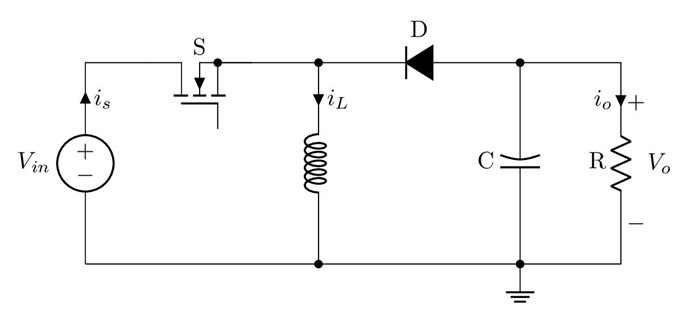
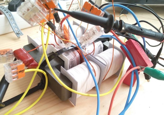
this is how it looks - 2 e-cores like A.Melnichenko uses. in my build i use POC-coils as output coils because for me it makes perfectly sense.
when you got the right frequency you will see how the output is pumped (CH4 - this is where the load is connected). my input is from halfbridge topology (CH2). CH1 is my primary which is in series resonance with capacitor. CH3 is one leg from POC output coil.
Jagau
posted this
01 September 2022
- Last edited 01 September 2022
Hi Chris I admit that it is not easy to understand, but when you dwell on it there is an explanation for all of this.
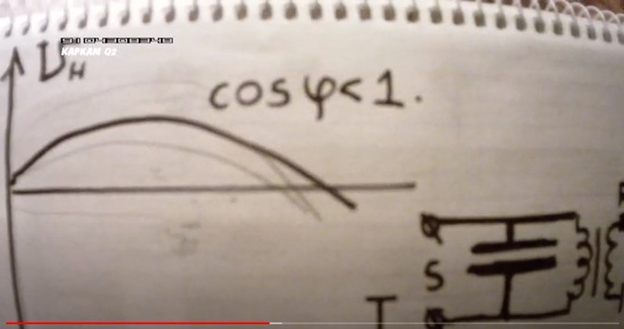
To make a real-life analogy, most large energy consumers face this problem. Especially those that use big powerful motors. Fortunately there is a solution to this and it is called power factor correction. There is therefore a way not to lose everything that has been read by the standard meters in order to pay a fair bill to what it is meters read by correcting Cos phi.
The average power absorbed by a purely inductive circuit will always be equal to 0 watts
To come back to the example of Melnichenko's experiment, we are in the presence, at primary side, of a purely inductive circuit. So the phase angle between the voltage and the current will be close to 90 degrees (in an ideal lossless xfo). But it is well known in the real world that there will be a small loss and most of that power will be returned to the input minus small losses.
So if we recover almost entirely the power lost, the actual consumption at the input will only be a few milliwatts (the lost).
Melnichenko, in order to recover this loss of power, placed an incandescent lamp in the primary and in this way he almost completely recovers the power in this incandescent lamp which otherwise would have been lost.
But without any increase power at the input.
There is no miracle here, it's just that he took Tesla's advice in a patent already mentioned earlier in this thread.
If you think this is the Melnichenko effect, that's not the melnichenko effect, then you misread this thread. Reread the principle of the separation of fields and the non additvity of waves.
So Pin = 33 x 0.102 = 3.37W, which is close to my earlier calculated input power of 3.6W.
Do you think Itsu actually understands what's been said and what's actually required to measure Input vs Output? I believe his buddy has Zero Idea what so ever! Itsu is getting closer, but still some ways off yet, in both measurements, Understanding, and actual Experiment!
Why is Itsu still a ways off in his Experiment? Why has he still not achieved the actual Operation which has been laid out HERE by Jagau?
I do so very much wish others would pay attention!
Do you see why WE are world Leaders and the other Forums are still Light Years Behind! Please catch Up!
Jagau
posted this
30 August 2022
- Last edited 30 August 2022
Hi all
Maybe off topic but I wanted you to benefit from an excellent YT which was shared by birdeye on the other forum which I find very very instructive to study. Take a good look at how he handles the bicycle wheel. It made me understand in a visual and very simple way, what is the Larmor frequency as well as other terms which will seem familiar to you, you will appreciate it I think.
There is an equally interesting sequel on his YT channel.
scalarpotential
posted this
30 August 2022
- Last edited 30 August 2022
the area under the curve represents the amount of magnetic flux which is actually present.
the guy in the video from university did not mention, that energy is stored inside the coil. maybe he thinks all of the audience knows that but i'm sure most of them did not.
it is also funny, that if someone wants to step voltage down from 24V to 12V the ON-time from halfbridge has to be 33% - does this sound logic? we can produce voltage for nothing they told us... why is it not linear? 😎
have a nice day!
Hi, the area under the voltage curve is volt-second and is equal to ΔΦ, the total flux, like you said. 33% duty cycle for half voltage is logical: during 33% the coil is charged, magnetized with 24v, during twice that time it i demagnetized with 12v (or actually -12v) at steady state.
current steepness=V/L=di/dt, higher voltage over L, steeper current ramp. .
Jagau
posted this
30 August 2022
- Last edited 30 August 2022
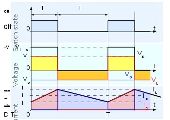
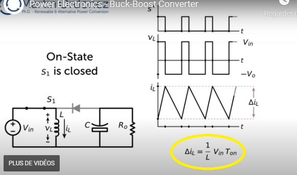
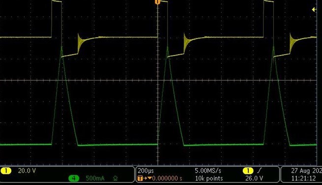
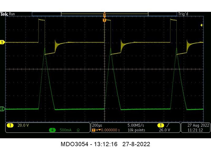
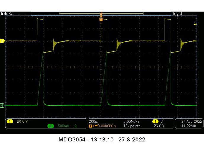
It is very important to make the difference in using the right formula. When your circuit operates in CCM mode Chris provided you with a video and this is the one used,
If your circuit works in DCM , Like that of Melnichenko, the formula used is very different and this is the one used.
This formula is derived from an integration.
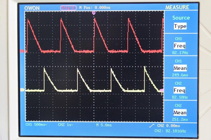
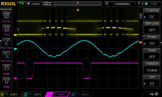
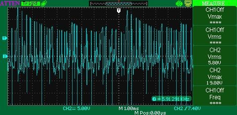
And the cuurent look like that,green curve. Photo provide by Itsu
You probably know that an inductor or a capacitor does not consume power because it is returned to the circuit. It then becomes very difficult to calculate the input power of a flyback. Its instantaneous power can easily be found for a short period but for a long period it must be calculated in rms voltage equivalence in order to have an idea of the input power because the RMS voltage and current are defined based on the mean power: each one is derived from the square root of the mean power.
The average power absorbed by a purely inductive circuit will always be equal to 0 watts The instantaneous power of a purely inductive circuit can be calculated but will give us information on one cycle only and can change from moment to moment. As Chris has already discussed, this power can be positive as well as negative. So you can see that it's not always easy to give the right answer as some people think, but we're working on it here.
the area under the curve represents the amount of magnetic flux which is actually present.
the guy in the video from university did not mention, that energy is stored inside the coil. maybe he thinks all of the audience knows that but i'm sure most of them did not.
it is also funny, that if someone wants to step voltage down from 24V to 12V the ON-time from halfbridge has to be 33% - does this sound logic? we can produce voltage for nothing they told us... why is it not linear? 😎
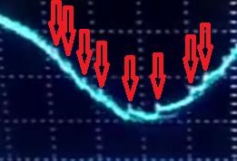
My Friends, focus on the Area Under the Green Current Trace:
Is there More Current on the Demagnetisation Phase or the Magnetisation Phase? Its Asymmetrical Right?
Please Note: This set of scope shots do not show AU, we have no conclusive evidence Itsu has yet achieved AU yet! More work is needed! At least Itsu now has a Waveform that should be represented!
First i salute Chirs and Jagau and also the other guys who worked on this project i am amazed by the results ,while watching youtube experimenters i come acros Master ivo wich have nice experiences ,so i think there is a connection with the work you are doing here on melnicenko efekt if you watch the video carefully you will notice some similarity with this experiment ,please watch till the end to understand exacly what is going on , he uses bifilar coils and he extract the usable energy with less consumtion . tesla sad in his bifilar coils patent that by using bifilar coils he amplify the magnetic fiel of the coil very much so this is the video i hope it helps on this project and can be improved . and the bifilar coils dose not necesarly have to look like pancake , this is the video
Chris
posted this
26 August 2022
- Last edited 26 August 2022
Hey Jagau,
I hope Itsu Respects your effort and ability and Reliably follows your Advice and Guidance Jagau!
I hope he Respects your Assistance!
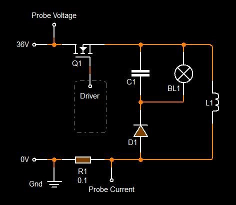
Itsu should be measuring the Input Circuit also and NOT all the spirrious Components he has added before the actual Circuit:
Itsu should be measuring after C1 and NOT before C3 which is not marked. This is a very bad Measurement Practice! Very Bad! These Components are NOT Part of the DUT and should NOT be Measured as part of the Input to the Circuit!
This Circuitry consists of High and Low Pass Filters, including the Common mode Choke, and other components, which will skew the Signals entirely! Why Filter a Signal you're attempting to measure? All of these components have their own Losses also which is NOT Considered!
This is VERY BAD Measurement Practice!
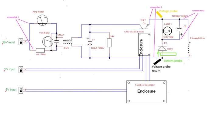
This is how the Input Measurement should be measured:
Replace the 0.1R Resistor, R1 by the Isolated Current Probe if you have one!
Jagau has given you the Correct advice already:
Any Accurate Measurement should always be as Close as Possible to the DUT, Device Under Test and an effort should be made to exclude any Un-Necessary Circuitry that is NOT Part of the DUT!!! This is really Important and is basic Engineering Knowledge!!!
What we have seen is VERY BAD Measurement Practice!
Chris
posted this
26 August 2022
- Last edited 26 August 2022
Hey Jagau,
It seems the Guru's are having all sorts of simple Measurement Related Troubles:
To minimize the loading effect of the probe, clamp it at the low or ground end of a component lead when possible. This method also minimizes noise or stray signal interference. This is a Tektronix recommendation
Correctly Drawn Circuits with Measurement Points should be provided as standard. How about we give them a leg up and let them know where we take our measurements from in the Circuit?
Jagau
posted this
26 August 2022
- Last edited 26 August 2022
Found a video clearly explaining how to calculate the parameters of a flyback with the formulas you will recognize. She is a young E.E. who explains very well flyback configuration parameters in DCM mode.
Jagau
posted this
23 August 2022
- Last edited 23 August 2022
Thank you for your great post Aetherholic. I see that some have understood that integral calculus is important in our steady-state circuit input measurements as described so well by Atherholic. We now have 2 ways to measure ourselves and be sure of our measurements.
Now to advance even further in power electronics input measurements, I am attaching a video from EVblog which explains in detail the integration function that only the most advanced oscilloscopes have.
You will notice that this function is used to measure the consumption at the input of its microcontroller, the way it does this is by the integration function which calculates the peak to peak voltage of the integral of the curve.
We are talking here about a voltage related to time called Time domain value.
That is why there is fortunately another way to calculate it accurately with the formulas that I and Aetherholic have provided to you.
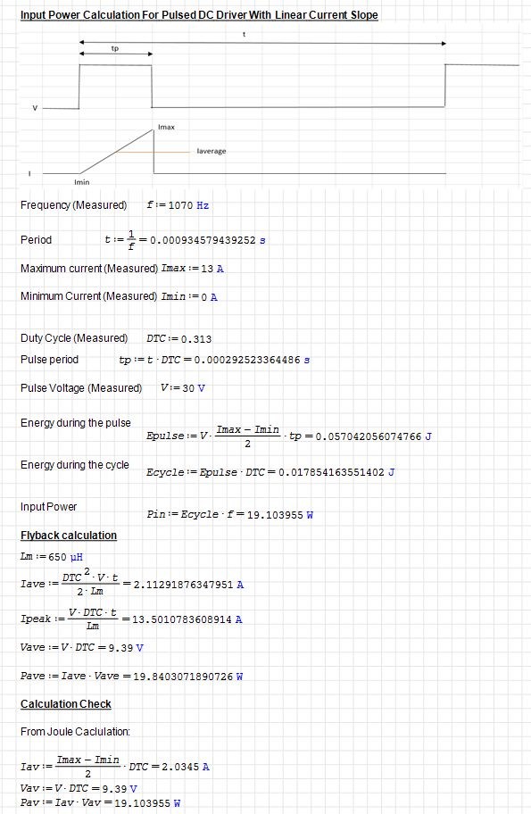
Here is my input calculation in Joules together with a corresponding Flyback calculation that Jagu just posted. So now you have two ways for calculating the power from different measurements.
This was done in SMath Solver which I like because it verifies the units so its a great check for calculations. Smath Solver is freely downloadable.
Jagau
posted this
22 August 2022
- Last edited 25 August 2022
Hi all
As Aetherholic said:
Put black tape over your psu meters. OU is being hidden in measurement errors.
Since the DC values measured at the input change over time, you must integrate these calculations in order to have a correct measurement.
To calculate the average DC input power of your circuit the voltage and the current will have to be integrated over time.
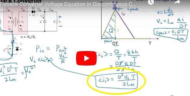
The average power of a flyback in DCM for discontinuous conduction mode is calculated this way
since we are in pulsed DC not changing in polarity:
Average Power = Average Voltage X Average Current
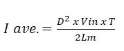
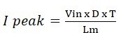
a second formula in DCM if you know I peak is
I ave = 0.5 X D X I peak
first 0.5 is for half of square wave, because we have a triangle waveform and we take only half.
To find I peak
as you notice, we take into account here the duty cycle and the frequency T=1/f
With this formula of the average integrated current and the value of your inductance you can check if you have the right pulsed current value by doing the reverse calculation. Allow yourself a 5% margin of error due to inductor losses and parasistic inductance.
More simple for voltage calculation
note than in DC Rms and Ave have same value
V ave or Rms = Vin x square root of D
These two formulas well known to flyback manufacturers are derived from integration.
Jagau
posted this
17 August 2022
- Last edited 17 August 2022
Hi Thaelin We are all equal here Thaelin, we experiment and do it at our own pace, no one is rushing us and as I said before you are under no obligation to anyone and the same for me.
For the Melnichenko effect that you have seems satisfactory and for the ferrites they can be replaced by iron in small insulated plates as mentioned by Melnichenko. Good experiences
Chris
posted this
16 August 2022
- Last edited 19 October 2022
Hi Thay,
Re:
Me and POC coils had a real adventure. Seems I did it right but never could see the wave form Chris shows.
Its really really easy to see a Triangle Waveform! Its the Natural Waveform for Lenz's Law.
I was showing this waveform in the thread: Some Coils Buck and some Coils DONT where I showed the difference in Waveforms and how the winding of a Coil does make a difference to a machines operation:
Lenz's Law is by Default, a Sawtooth Waveform and this is about as easy as Breathing, to show implicitly on the bench! The Buck Boost Circuit shows this simple operation every day of the week, its a very basic, beginner level circuit that any one can manage with no trouble at all!
The trail of Bread Crumbs shows us:
There are some that will show you a Rock and tell you its a Diamond, these people can not be trusted!
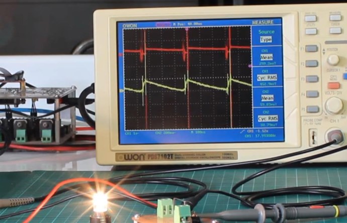
Ok, this seems something simple even I can do. I have on hand 2 rolls of standard lamp cord. This is easy to strip down into a single wire but is stranded inside. Will this work for the coils? I have some 1/2" cold roll rod that can be used for cores. Past orders for ferrite came broken to pieces.
If I am going to do this, I want to know all the right things up front. Me and POC coils had a real adventure. Seems I did it right but never could see the wave form Chris shows. Did fair but not good. Power supply is a Rigol 0 to 30 @ 5 amps and can limit current draw with it. Many sig gens around at the moment. Even have an arbitrary wave generator as well.
So give me a heads up if this will fit the needs for this. I do want the crew here to know I am experimenting in the background but mostly silent. I usually feel as if I have nothing worth while to say. Even was told once to go back and study electronics 101. That was an insult far as I am concerned.
Chris
posted this
15 August 2022
- Last edited 15 August 2022
My Friends,
Jagau is correct!
Beyond making a nice flyback
We could not be more disappointed with Itsu's effort to fail! The simplest Circuit, and Itsu tried his utmost to fail at it! We are absolutely astounded at the publically visible effort to fail at the most Simplest Circuit!
One must think more broadly about this Circuit and what it is doing!
The Sawtooth Waveform is the defining waveform for Pumping Current! You need the Sawtooth Waveform!
The Sawtooth waveform Pumps Current! This is the Pump, Amplifying Current! Voltage, it is "Generated" and Faradays law gives you the equation for this! Amperes Law gives you the Magnetic Field Density and Strength!
It surprises me how little effort some people put into understanding the most simple things! Those with decades of experience are either really really dumb or Trolls trying to distract and deceive the Community! There is no possibility of failing for this long other wise!
Chris
posted this
11 August 2022
- Last edited 13 August 2022
My Friends,
And there you have it... Troll Strike Thwarted AGAIN! 😎
My Friends, here on this Forum, are Successful and have given EVERYTHING you need to succeed! Aetherholic was kind enough to verify this, and give you all Excellent Advice!
COP = 20 in a different but not too far removed configuration. And no im not going to post it, just to ratify the effect is real. (measurements verified by scientific report) and loopback self running. Trust in Jagu and Chris and all the information Chris has provided. 2000% the truth.
PS:
Put black tape over your psu meters. Use an integrating power meter with high sampling rate rate for the input power. Alternatively, use oscilloscope and use the calculation I will post in a separate thread tomorrow which is a simple verified equivalent. OU is being hidden in measurement errors.
Aetherholic - One truth, One field
Thank You Aetherholic!
I want to say a massive Thank You to Jagau!
Jagau is a First Class Human Being! I am proud to call My Friend, as is Aetherholic and all here! We ONLY Ban Trouble Makers!
The TRUTH is Right here and its Easy and Cheap, you only need implement it as we have!
Here in Australia, we have a Term: Numb Nuts, seems this fits well in this situation where the Stupidity we have seen from some people, just threw Gasoline, onto the already Burning Trolls, we set Fire To! Oh dear, how sad, never mind! These people are very very low IQ Buffoons!!!
Stupendously Stupid People always say and do Stupid Things! There is no helping these people! They cant help themselves!
To Be Clear: Itsu does not fit these categories! I am not talking about Itsu! Itsu could do so much better if he removed the Noise from his Ears and more closely followed instruction! I am not sure he wants to however? Itsu should have been able to manage a: Standard Buck Boost Converter don't you think?
It is true, some have no idea about Energy Machines and they choose to stay Blatantly Ignorant on these same machines, all while pretending to have special interest in them! That's why they have many decades of Continued Failure! A Constructed Failure, like a Movie would have a Plot to Fail! Its called Paltering, pdf attached.
We are Light Years Ahead! This Thread and many more here, are Proof!
Jagau
posted this
11 August 2022
- Last edited 11 August 2022
hi all
Finally back from another excursion.
I took the time to read some statement and all I wanted to do is close the topic and not share anything more. When I read the last message from Aetherholic it gave me hope to continue but it didn't take long for me to stop all that.
Some wants to make me pass like a madman but unfortunately this is not the case, extremly disappointed with the attitudes of other researchers on other forums. I never thought one day I would be hated because I got a little ahead of the others. I agree with Chris's thoughts and I understand even better now that it is not good to share everything, cursed jealousy. Whenever someone finds something interesting, we make him look crazy. I even received several disturbing private messages.
You do well Aetherholic not to say everything and shared I understand you, thank you for the encouragement. Don't make the same mistake I made of sharing too much.
Finally for those who think they have tried everything, you have misread Melnichenko's patents. No one has yet told me about current phase shift and reverse magnetization, re-read the patents don't wait for me to tell you what to do that won't happen.
All I've seen of you all so far are just very simple little flybacks, A beginner in electronics can do this easily. You are supposed to be valuable researcher, stop relying on others to succeed, experiment, it doesn't hurt and for those who talk to me about the cost, stop it right away you are not on the right track. There is no enigma here, learn to read and understand Melnichenko's patents, I didn't write them. Maybe you think he's crazy too.
@Itsu, as replicators and like thousands of other replicators around the world, get out of the way that I owe you something and it's the same for you, you owe me nothing. We are entirely free to reply or not to reply, there is no obligation, blame yourself and the misinterpretation of Melnichenko's patents if you have not succeeded. I trusted you and you lost it, your true personality came out. I must say that I had been warned.
Aetherholic
posted this
11 August 2022
- Last edited 11 August 2022
My first post in a long time.
COP = 20 in a different but not too far removed configuration. And no im not going to post it, just to ratify the effect is real. (measurements verified by scientific report) and loopback self running. Trust in Jagu and Chris and all the information Chris has provided. 2000% the truth.
PS:
Put black tape over your psu meters. Use an integrating power meter with high sampling rate rate for the input power. Alternatively, use oscilloscope and use the calculation I will post in a separate thread tomorrow which is a simple verified equivalent. OU is being hidden in measurement errors.
Chris
posted this
10 August 2022
- Last edited 10 August 2022
Gyula,
thanks for the extensive point by point analysis, this is a skill i lack still and very useful.
Like Chris, i would like to see some different kind of signals coming out of this circuit (less input and more output preferable), but the scope does not lie and presents these conventional signals belonging to this conventional fly back circuit.
I can not magically change those signals to something more promising, it is what it is.
I tried both the original Melnichenko circuit and the modified by Jagau circuit with several coils and cores, but they all stay within the conventional 70 to 90% efficiency range.
I still have some modifications pending on the L1 and L2 coil / core, presented by Jagau, so we will see if it will change much.
You need to think Simply about this and NOT complicate these very simple things that entry level Electrical Engineers have mastered: Standard Buck Boost Converter
Waveform:
Any Alternating Current there? Or is it Purely a DC System? Hmm Trolls everywhere!
Which is as we have shown!
Yes, this image of the current is very important and
I confirm that I also find it in the Melnichenko thread effect.
Very Simply, follow what we have given you! There is nothing hard, complex, or difficult to any of this!
Only Trolls try to over complicate simple things! They Lie, Cheat, Steal and make a concerted effort to confuse others! That's their job! Stupid people with big mouths and very very low IQ's also qualify BTW!
That's why we are Light Years Ahead! We have eliminated all Trolls! We have made massive progress because we are a Troll Free Zone!
Best Wishes,
Chris
P.S: A Well Designed Buck Boost Implementation can be around 99% Efficient! So how do we push this Dogmatic Boundary? The Answer is right in front of everyone's face! Plain, Simple, Straightforward! Cheap and Easy! Aboveunity.com has given it to you!
Chris
posted this
09 August 2022
- Last edited 09 August 2022
My Friends,
I see Itsu's frustration:
Concerning replications:
When an inventor (Melnichenko) or a replicator (Jagau) claims a certain effect (like COP > 1 by both), and REQUESTS other replicators to join them to confirm this claim, it is IMHO the DUTY of the claimant to provide the replicators with ALL information needed to come to the same result (COP > 1).
If you want to entertain people by presenting puzzles to them, you should not REQUEST for replicators to join, but puzzle enthusiasts.
Throwing bread crumbs and expecting the replicators to figure out how it works without showing the used circuit, some in- and output measurements, components used, etc. will quickly raise the suspicion that the claimant does NOT have anything special to show and is provoking the replicators to connect the dots and find the effect for him.
I know Jagau is not such a person and there are probably some other factors involved why he is so reluctant to provide details of his working circuit, but this leads to nothing and only gets the honest working replicators frustrated (not to mention the costs involved).
We are all in this for the benefit of humankind, so playing games on "who is the best" or "who is light years ahead" or "who knows it all" is childish the least and bordering to unacceptable behavior IMO.
Itsu
And, in defense of Jagau, I advised against sharing too much information! Sharing too much Information makes one a Target and one is ENDLESSLY Harassed like Captainloz was and as a result the researcher ends up going quiet and no longer being an active part of the community!
Captainloz gave you 100% of the data, as has Jagau, and you still cant make it work!
In the end, we have given you 100% of the data! Its all here on THIS Website!
Polarity of L1's Voltage changes at Mosfet TOff, the CURRENT Does NOT!
Polarity of L2's Voltage and Current do NOT Change!
This is purely a DC System and there is no AC Component here!
Voltage is Generated in L2 at Mosfet TOn and the Potential of BOTH L1 and L2 increase to VMax over Time t, at this point the Mosfet is turned Off, TOff, and the Demagnetisation Phase occurs!
The Demagnetisation Phase must always be longer in Time t than the Magnetisation Phase!
Through this entire period, L1 and L2 oppose each other!
Jagau is NOT Responsible for Itsu's lack of Understanding! And is not responsible for the lack of Required Study!
Of course, for the community, we need to make sure that Good people get enough information to make a replication, and the Greedy, Capitalistic, Opportunistic, just looking for a Patent Score, are left in the Wind! No one wants these sorts of people around! There is no progress when one steals it and patents it is there!
So, Itsu, I feel your pain, but at the end of the day, your frustration stems from a lack of basic understanding in Electromagnetic Induction and How Coils can show Interactions that are not currently in any literature, anywhere, except on this site: www.aboveunity.com with Hundreds of Examples and Demonstrations!
Captainloz removed some of his videos because he was being harassed so much by the way and he and I communicate outside the forum now! How sad is that!
Best Wishes,
Chris
@Jagau - Just ignore the Harassment! I have had it for years! It doesn't go away, but focusing on the evidence shows how much others still yet have to learn!
We can NOT LEARN FOR THEM!
Also, don't forget, some are out to make a Mockery of the Evidence and try to make it look like machines don't work when the truth is they do! Some are Paid Dis-Informationilists with very low IQ's! I have your back My Friend!
P.S: Some of these people were the Super Trolls I had nothing but problems with over at one of the other forums! Itsu was not one of Them! Read more Here and Here! Remember this Girls? Wow have we set fire to a bunch of Trolls! Trust the Plan!
Concerning the polarization of L2 in the above screenshot with the voltage and currents, it deliberately is chosen that way so that the power induced into L2 comes from the "demagnetization phase" aka "collapsing magnetic field phase" aka the "bemf phase" of the cycle, as that is, according to Melnichenko and Jagau, where the free energy comes from. Jagau correct me when wrong!
The below screenshot is from when the L2 connections are swapped, so showing the other polarization effect of L2:
We see that now the Power into L2 is induced during the magnetization phase of the cycle which is, according to melnichenko and Jagau, NOT where the free energy comes from. Jagau correct me when wrong!
If those signals are still wrong, even when they are coming from a close replication of the circuit used by Melnichenko, then the circuit is wrong or the effect claimed is not there.
The Conduction of the Diodes only stops if the applied voltage polarity changes or drops below the break over voltage! All Coils should not change their polarity during One Full Cycle! I have no idea what you're talking about? This is purely a DC System!
Potential goes Up, Potential comes Down:
Itsu, please try harder and follow the very simple instruction we have given!
Chris
posted this
08 August 2022
- Last edited 19 October 2022
@Jagau I agree, sadly... However, we have ALL Answers right here!
@All Readers,
The old Folk Tale of Sisyphus keeps coming to mind:
In Greek mythology, Sisyphus or Sisyphos was the founder and king of Ephyra. Zeus punished him for cheating death twice by forcing him to roll an immense boulder up a hill only for it to roll down every time it neared the top, repeating this action for eternity.
Sometimes I think this is in need of a more broad interpretation! I think we Humans have some VERY Bad Habits of doing things the absolute Hardest and sometimes most Impossible ways! We must think Simple! We must FORCE our minds to think Simply about things:
I have pointed people in the direction to observe the required effects for a long time now:
My Friends,
This thread is soon becoming one of the most important threads here on this forum.
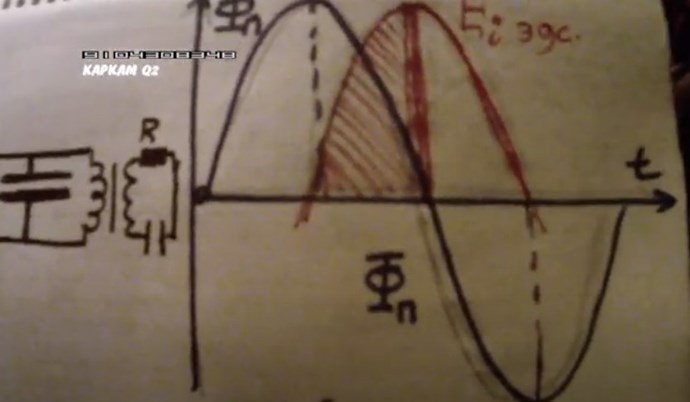
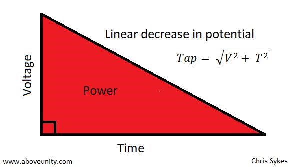
Time ( t ), time is a critical factor, it is a dependant factor in Electrical Energy; which is defined as Joules ( J ) per second. One Watt Hour ( Wh ) is: Joules ( J ) per second x 3600, because there is 3600 seconds in one hour. So, one Watt Hour ( Wh ) is equal to 3600 Joules ( J )
So, the "Generation" of Energy, is time dependant.
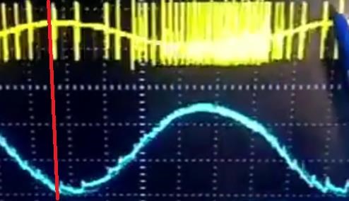
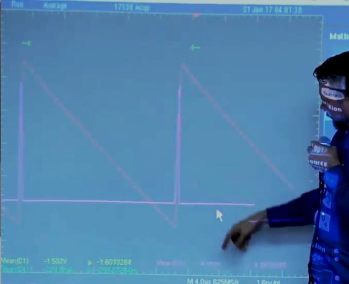
Lets observe this image in some detail:
You can see, we have Triangles in the Blue Waveform, clearly seen:
In the Blue Waveform, we see there is a line up of the Spikes, I have marked this in Red. These Triangles are the same as I have pointed out above:
This is where the Coils build up a Potential, this "Generates" Current, the Pump, the Tap is open for a Flow. Currents are Equal and Opposite. Lenz's Law, a Natural State, a state that Nature requires for a System to come back to Equilibrium. A closer look:
Its hard to see in a Sinusoidal System, DC Pulsing is a lot easier to see what's going on. Lets listen to one example:
This is wrong, its not how the Melnichenko Effects Works! L2 should be conducting a few micro seconds, D2 VConduct or break over Voltage, Delayed Conduction, D2 Conducts just after IGBT TOn! Itsu's Polarities are Incorrect!
I want to point out more, but at the moment, this is the first and most important issue!
Please go and read Itsu's post and thread if you have not already.
So, I cant help but get frustrated when I see these sorts of comments:
I was waiting for certain people to publish the secret, hasn't happened.
I was waiting for Mummy to put her tit on my mouth!
Very little Studding, Research and Observation done!
All Answers lay right under your Noses! On the ONLY,True, Open Source, Energy Forum in the World that has Real, Live, Working Answers, for all of Humanity! All Backed by Independent Replication, Sciences Verification of Truth!
Chris
posted this
04 August 2022
- Last edited 19 October 2022
My Friends,
Jagau is correct, some Coils work better than others! Largely this is due to the Coils Geometry!
However, If I may,
I would suggest Itsu stay with his current coils only checking the VOut individually on each Coil at TOFF on the Mosfet. Comparing VOut in a Single Scope Shot. Making sure the Scope Triggering is set to L1 only so we can see the Timing.
Then I would like to see a scope shot of L1 and L2's Currents, making sure the Phase is correct and the method defined, e.g: Conventional Current or Electron Current. Of course, this is to inspect the function of L1 and L2's Opposing Magnetic Fields, a Very Well Known Requirement as we all know!
Itsu needs to find the Resonant Frequency of the Coils individually, but in the current configuration! We need to know the range in which we are working in and compare to current frequencies!
Itsu last stated:
FG:1.5KHz @ 10% duty cycle
So, lets see where Resonance lays and compare. Don't forget, Reducing the Duty Cycle is like a Change in Frequency you could almost say. Coils behave according to Antenna Theory, so the fundamental Resonances are Important!
Region of Interest:
ROI ≅ L1 Resonance + L2 Resonance / 2.
Lastly, if Itsu can confirm the Turns on L2 vs L1, as L2 needs to be more turns, and we can go into this later on.
Some advice, stay on track! Look at the Effects First, then the Measurements! I expect you should have seen one or two anomalies on the scope about now! I guess if you're not looking?
Itsu, look for this:
Your 10% should be the Regauge Period! Look for this and work on this, this is Asymmetrical Regauging and once done right, you will see a whole new world open up for you! Your Input will be Insignificant compared to the Output! You know you have something when you gain this operation! Which is really easy!
Best Wishes,
Chris
P.S: All this has been covered here for many years now 😉
Jagau
posted this
03 August 2022
- Last edited 03 August 2022
Hi Chris
Itsu's works are going very well here, he makes a lot of effort to get a good result and I respect his ideas, he does various tests and several kinds of experiments like the last one with a linear load at the nput.
This is how we advance by experimenting. The most important recommendation is taking measurements, input versus output.
I'm pretty sure many have tried the Melnichenko effect but don't understand how to take and interpret their measurements and they may have been successful without knowing it.
I confess that I would like to see as many efforts of the members here. Many read here and don't share anything. Jagau
In physics, scalars are physical quantities that are unaffected by changes to a vector space basis. Scalars are often accompanied by units of measurement, as in "10 cm". Examples of scalar quantities are mass, distance, charge, volume, time, speed, and the magnitude of physical vectors in general.
You need to forget the Non-Sense that some spout with out knowing the actual Definition of the word Scalar! Some people talk absolute Bull Sh*t!
The pressure P in the formula P = pgh, pgh is a scalar that tells you the amount of this squashing force per unit area in a fluid.
A Scalar, having both direction and magnitude, can be anything! The Magnetic Field, a Charge moving, yet some Numb Nuts think it means Magic Science!
More than anything else, your contributions to this forum are most important! We are trying to actively get all visitors involved, but we do only have a few main contributors, which are very much appreciated! If you would like to see more pages with more detailed experiments and answers, perhaps a contribution of another type maybe possible:
Ere many generations pass, our machinery will be driven by a power obtainable at any point of the universe. This idea is not novel. Men have been led to it long ago by instinct or reason. It has been expressed in many ways, and in many places, in the history of old and new. We find it in the delightful myth of Antheus, who drives power from the earth; we find it among the subtle speculations of one of your splendid mathematicians, and in many hints and statements of thinkers of the present time. Throughout space there is energy. Is this energy static or kinetic? If static, our hopes are in vain; if kinetic - and this we know it is for certain - then it is a mere question of time when men will succeed in attaching their machinery to the very wheelwork of nature.
Experiments With Alternate Currents Of High Potential And High Frequency (February 1892).


 .
.


 as you notice, we take into account here the duty cycle and the frequency T=1/f