My Friends,
I am sad to report, the response from Itsu is not a sensible, logical approach:
For Chris,
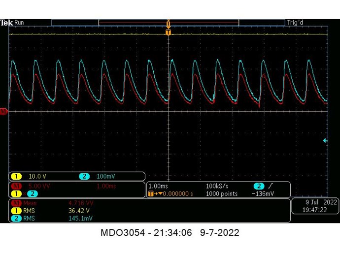
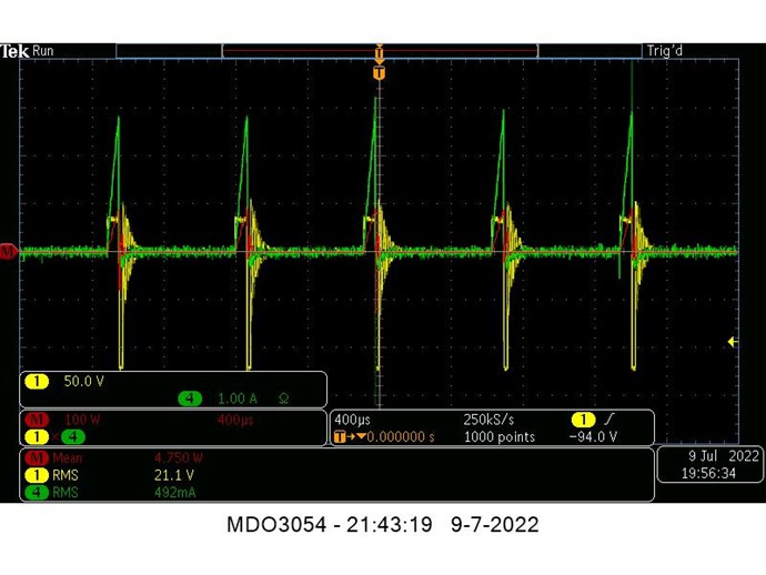
the beauty of power measurements with a scope is that the scope does not care what kind of signal it has, DC, AC, peak, square, sinuous etc.
It just takes millions of samples of the signals (not rms, not mean, not ...) from its buffer and multiply (in this case) those instantaneously getting millions instantaneous power values which then get averaged (mean) presenting the average power across that buffer.
So nobody is using rms value's to calculate power, those rms value's you see on the voltage and current are JUST a representation of the signals measured by the scope, it does NOT use them for calculating power.
I don't pretend to be a guru in anything, so please anyone with extended knowledge on scope power measurement techniques step forward and either confirm, deny and/or improve on my above statement.
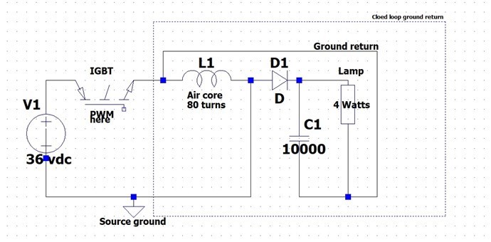
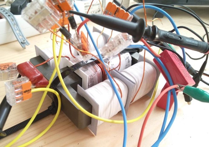
Concerning the dimensions of L2, i did use several different L2's, see above post #7, but all shows similar output value's (65 to 160mW), so i hope Jagau can shed some light on what dimensions he uses to get cop > 1.
Regards Itsu
Itsu
Ref: A Melnichenko effect replication
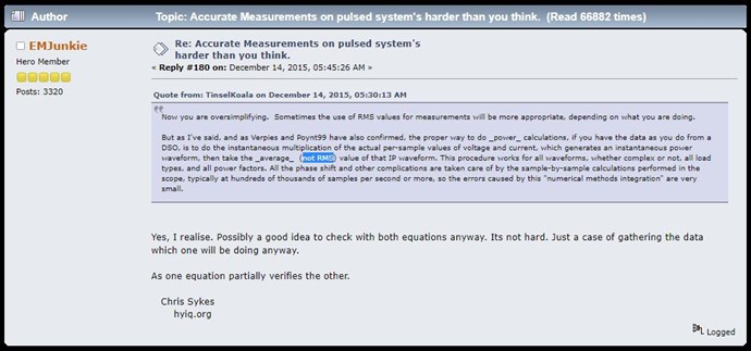
I understand what you are saying Itsu, I understand very well how a Scope works, Thank You.
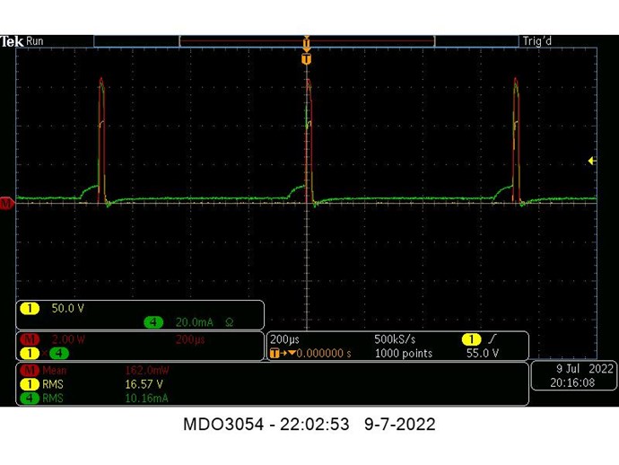
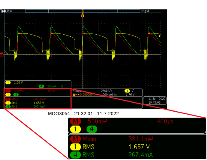
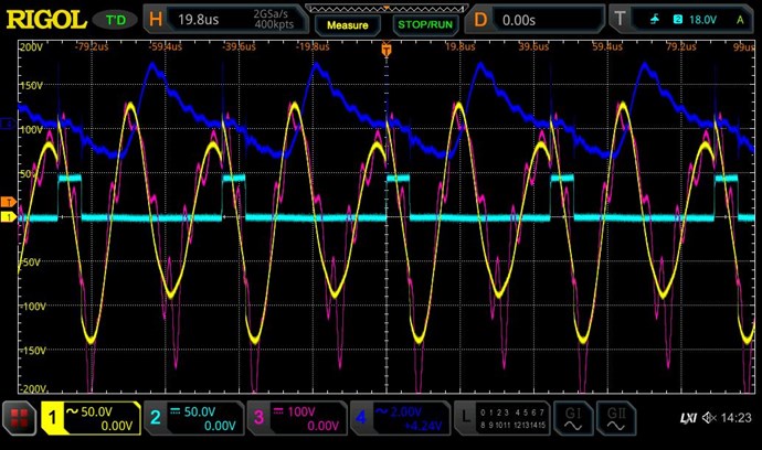
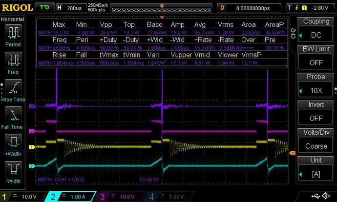
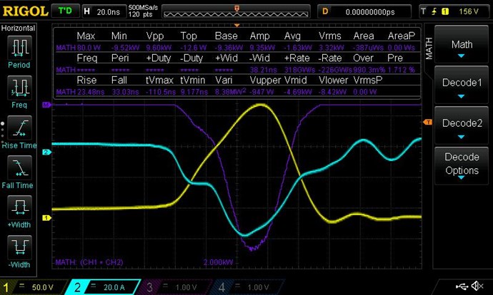
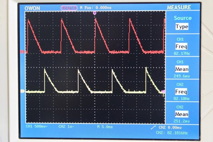
Your Scope is taking the RMS Values for that Channel:
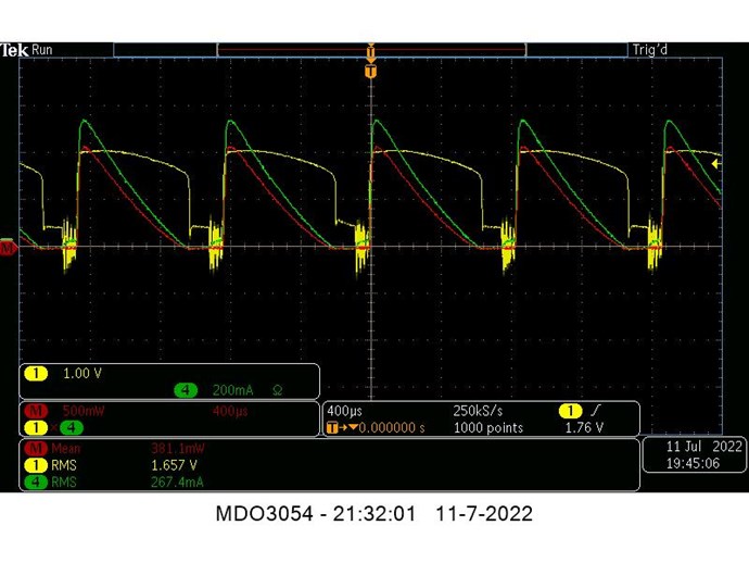
You are averaging: Instantaneous V RMS x I RMS = P in Watts
- 1.657 V RMS
- 267.4 mA RMS
Which is Wrong! You cant do it this way, not on DC Input! I know this scope shot is not your Input... But using this as an example.
Very simply, compare a Sinusoidal Waveform with each channel, one Mean and one RMS, the difference will amaze you! I have already shown this in the: Measurements Thread, if you go and Read it!
However, any setting on RMS means you have the Scope Calculating RMS for the Buffer Size across the data points captured.
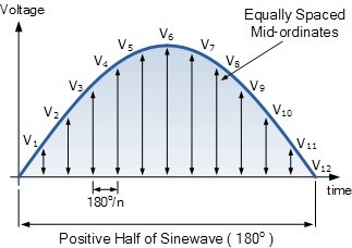
RMS is Specifically designed for AC, Alternating Current Only! It can NOT be used for DC, Direct Current, at all.
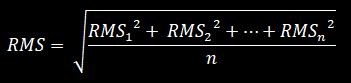
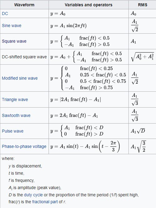
RMS or root mean square current/voltage of the alternating current/voltage represents the d.c. current/voltage that dissipates the same amount of power as the average power dissipated by the alternating current/voltage. For sinusoidal oscillations, the RMS value equals peak value divided by the square root of 2.
Ref: RMS Current
The Oscilloscope will take the RMS Value, if you capture the RMS Value, again, which is wrong! Please do the Math!
The term “RMS” stands for “Root-Mean-Squared”. Most books define this as the “amount of AC power that produces the same heating effect as an equivalent DC power”, or something similar along these lines, but an RMS value is more than just that.
Ref: RMS Voltage Tutorial
Its a real shame, because not a single measurement can be accurately represented, unless the Correct Data Points are Calculated! Its sadly a fact, that these are the same people, telling Itsu how to measure incorrectly, that have been telling everyone for decades, that their Measurement Data is wrong! I can show you thread after thread that states that you should use RMS on a DC Source, when you absolutely Should NOT !!!
Ask yourself, why have they insisted on RMS for so long? Is it a means to falsify the Data just in case others did get something of Value?
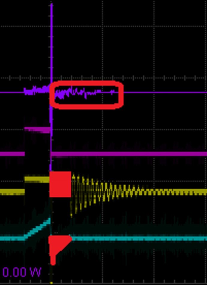
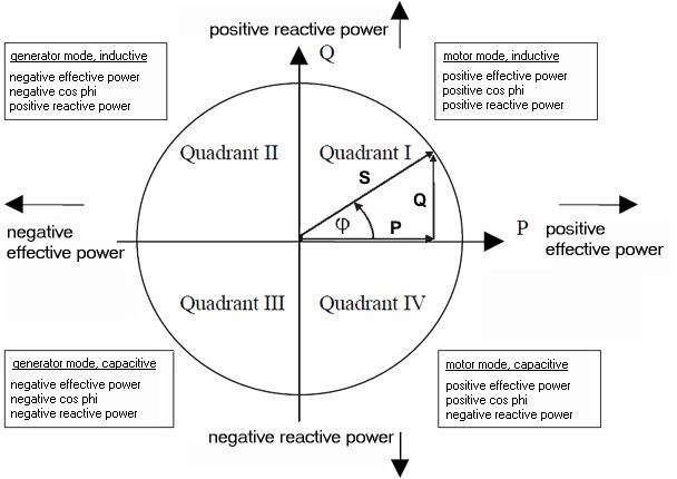
RMS can NEVER Measure any Negative Power, RMS is ALWAYS Positive, never accounting for any Reverse Currents! It Should NOT be used on DC if one wants Accurate Measurements! Should we not expect measurements to be accurate if measurements are to be given?
For those providing Measurements, they should be providing accurate Measurements, that are in-line, with Industry Standard Definitions, and Defined Values and Guidelines!
I have provided the evidence, the proof is right here, with References, if you persist to make in-accurate measurements, I can no longer assist.
This is Jagau's Thread and I do not wish to waste any more resources on his Thread, Sorry Jagau!
Best Wishes,
Chris


 .
.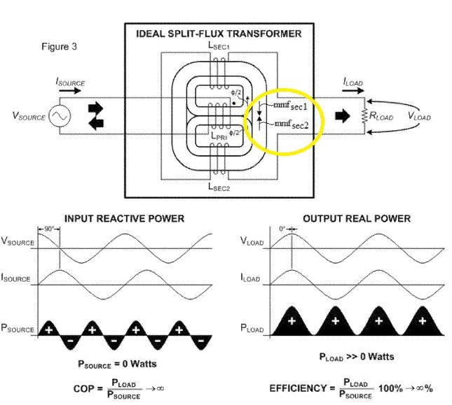


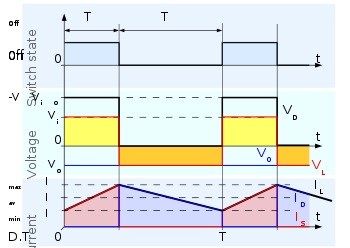


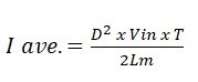
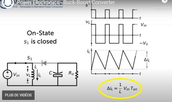
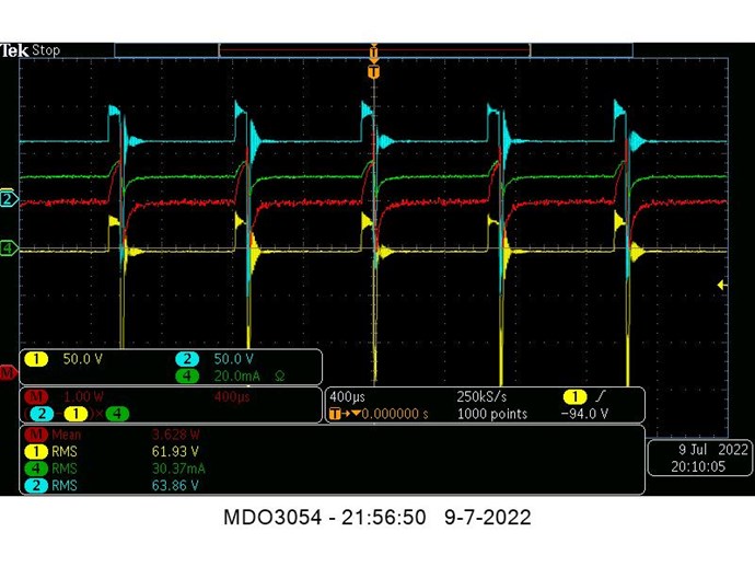
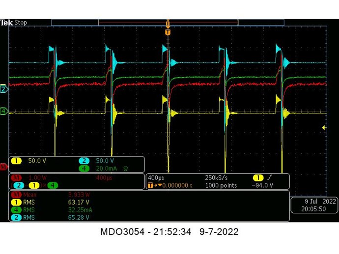
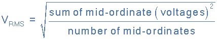
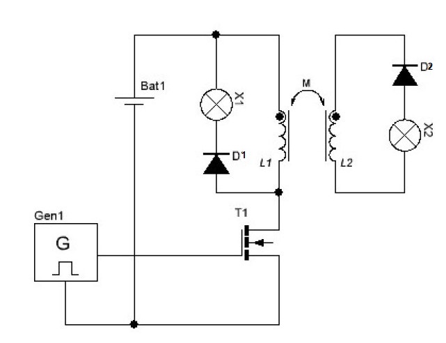
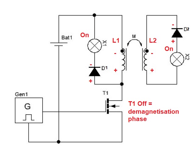
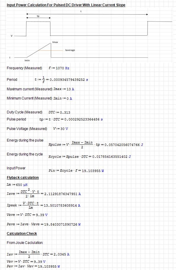
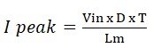 as you notice, we take into account here the duty cycle and the frequency T=1/f