My Friends,
Be it known, I am still working in this area, for some this might be easy, for me, this is not so easy.
I have deliberately left this topic last, for a very good reason! Voltage, what is Voltage and how is it "Generated"?
Bucking Coils Voltage Requirement!
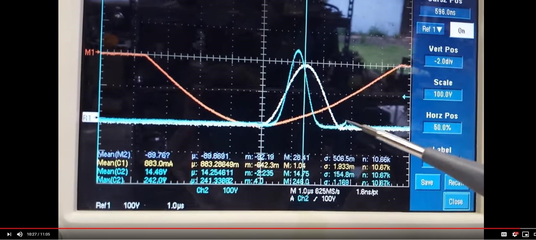
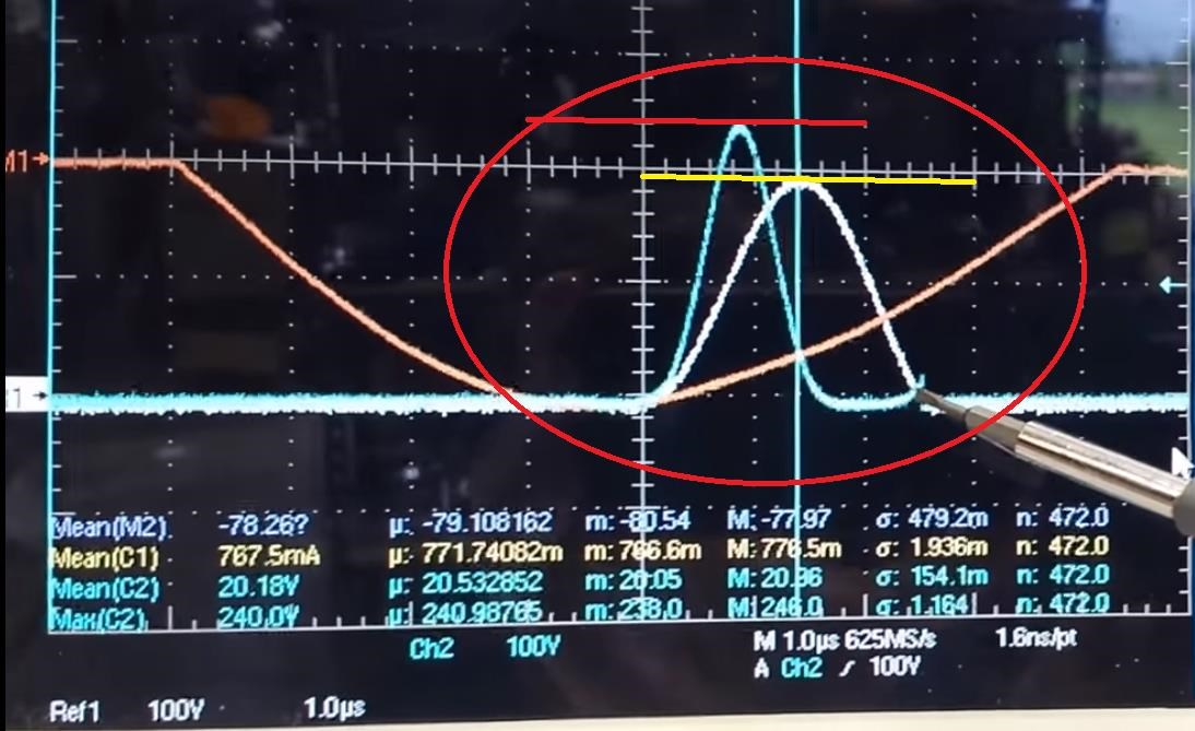
From the early days, we have had problems with Voltage! At one point I asked the question in one of my Mr Preva Experiments, why such a large Voltage Drop?
Yes, Faraday's Law predicts Voltage!
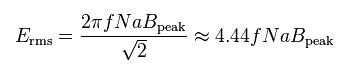
In a Transformer the Voltage is given by:
VRMS = 4.44 N f ΦPeak A 10-8
Floyd Sweet told us, straight up:
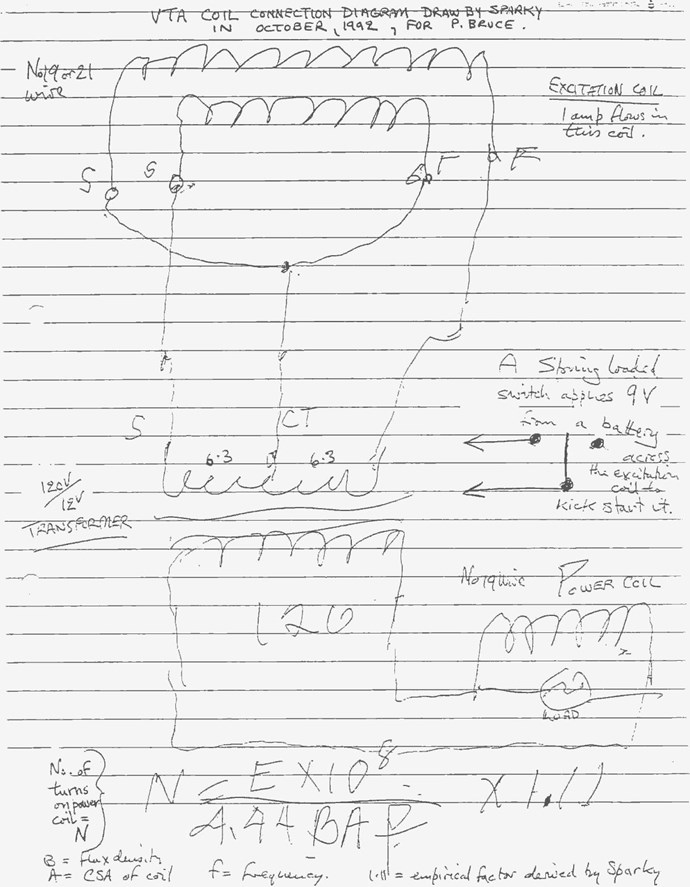
Note: My research led me to believe Floyd Sweet was fond of Peter Bruce, and I believe if anyone has the full, true story on the VTA, it will be Peter Bruce, but I have never been able to get hold of him.
Which is a rearrangement of the above Transformer Equation, to get Turns instead of Volts rms.
Floyd Sweet Defined Voltage like so:
Voltage: The energy transfer capability of flow of electric charge is determined by the potential difference or voltage through which the charge moves. A charge of 1 coulomb receives or delivers an energy of one joule or watt-second in moving through a voltage of 1 volt or V = dw / da.
For my poor old brain, some studding to understand that! The Charge Potential Difference between two Terminals, Coulombs of Potential.
Even in The Mr Preva Experiment, we have all had trouble with getting the Voltage up, it sounds like a simple task, but it is not as easy as one would thing!
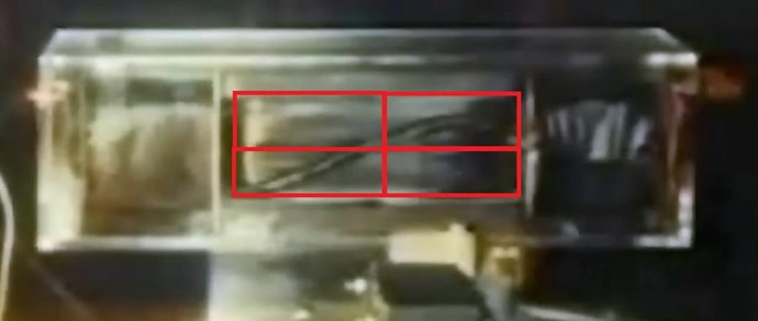
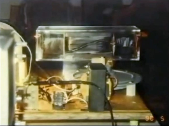
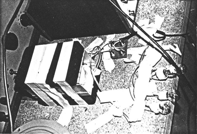
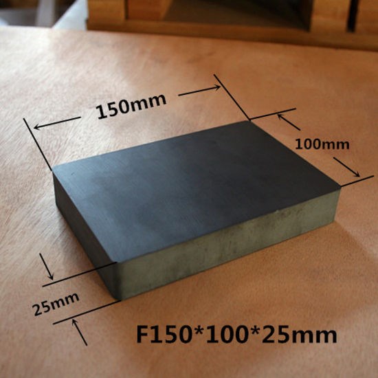
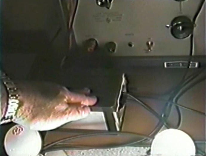
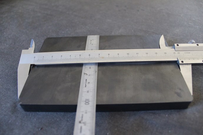
We know, Floyd Sweet especially, worked hard on increasing the Cross Sectional Area of his Coils so he could have less turns of a thicker wire gauge, we have Visual evidence and also Lab Note Evidence for this.
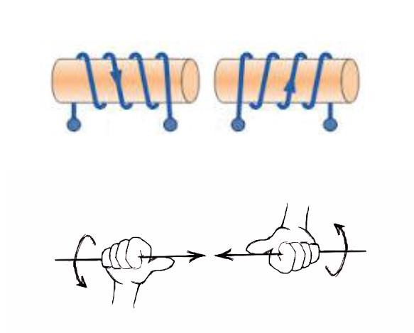
Now, our Partnered Output Coils:
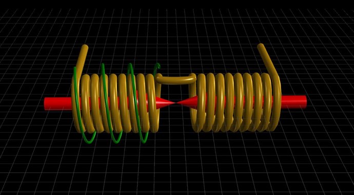
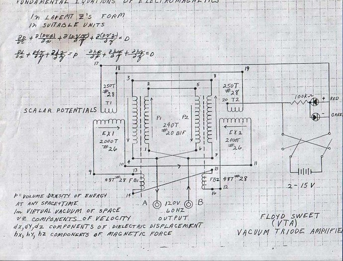
I pointed out the Turns relationship on the VTA Thread between the Coils:
On the Topic and Point of Transformers and Floyd Sweet being a Transformer Expert, What are the turns Ratio we see: 1 : 5 = 48 Turns to 240 turns! So 240 / 48 = 5 right?
Ok, another point no one has ever bought up: 120 Volts / 240 Turns = 0.5 Volts per turn. 48 * 0.5 = 24 Volts, what did we use to start the VTA? 2 - 15 Volts right. So whats the chances the Turns Ratio are so close?
A Transformer? Yes of course the VTA is a Transformer variant!
We will always have those with their own opinion, however, an Educated Opinion has worth, an uneducated opinion is worthless! Beware those Un-Educated opinions! They will steer you down all sorts of Rabbit Holes!
The VTA was, plain and simple, a Generator and a Transformer all in one!
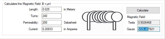
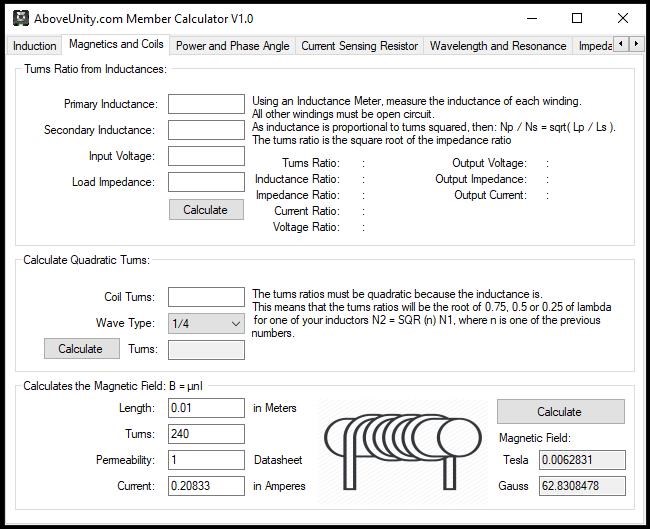
If the Gold Coil on the Left, POCOne, has a Sinusoidal Current of 1.0 Amperes at 50 Hz, to "Generate" a Voltage in the Right Gold Coil, POCTwo, of 20 Volts, then what else do we need to know? Length = 0.03M, 9 Turns, Permeability = 1000, now this gives us, B = 3769.9111843 Gauss or 0.3769911 Tesla.
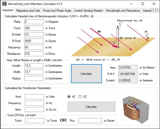
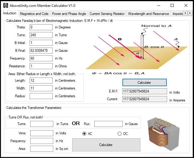
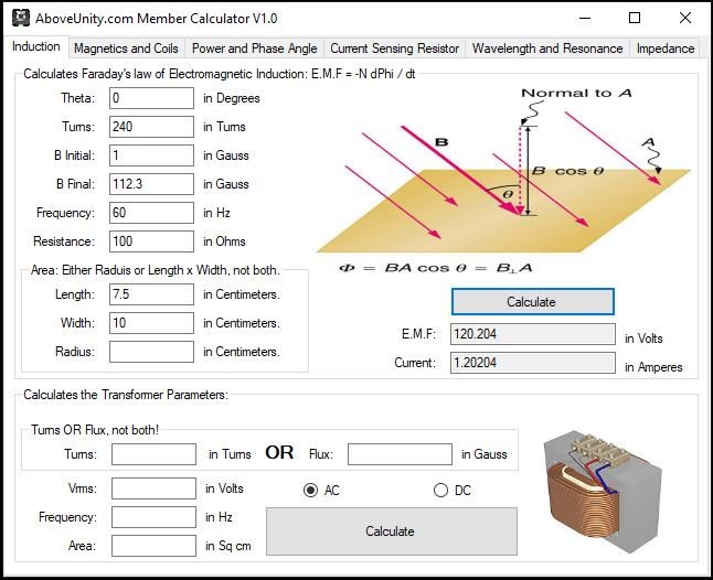
So, if we plug this into our Faraday's Law Calculator:
- Area: 0.121922069293166 Meters (m) Squared or 12.1922069293166 cm squared.
- Theta: 90 Degrees
- B Initial: 0.0001 Tesla
- B Final: 0.37699111843 Tesla
- Delta B: 0.413562105514813
- Delta T: 0.02 Seconds
- Voltage: 20.6781052757406 Volts
- Amperes: 6.89270175858021 Amperes
Of course, this does not work out in the way we have tried to work out, if we try this, build it, configure the right Feed Forward and Feed Back Currents, we don't get this as we would expect. Why? Whats stopping us? Why cant we make this what should be a simple calculation?
The Aboveunity.com Member Calculator can be used to calculate the B Field, and the following class can be used to calculate Electromagnetic induction:
///////////////////////////////////////////////////////////////////////////////////////////////////////////////////////////
///   ****************************************************************************************************************   //
///   Written by Chris Sykes                                                                                             //
///   Copyrght 2016                                                                                                      //
///   --> Application Name Goes Here <--                                                                                 //
///                                                                                                                      //
///////////////////////////////////////////////////////////////////////////////////////////////////////////////////////////
namespace EScience
{


    #region Using Statements:

    using System;

    #endregion


    public class FaradaysLaw
    {


        #region References:

        // See: http://farside.ph.utexas.edu/teaching/302l/lectures/node95.html

        /*

         * A plane circular loop of conducting wire of radius $r=10$cm which possesses $N=15$ turns is placed in a uniform magnetic field.
         * The direction of the magnetic field makes an angle of $30^\circ$ with respect to the normal direction to the loop.
         * The magnetic field-strength $B$ is increased at a constant rate from $B_1=1$T to $B_2=5$T in a time interval of  ${\mit\Delta}t=10$s.

         * What is the emf generated around the loop?
         * If the electrical resistance of the loop is $R=15\,\Omega$, what current flows around the loop as the magnetic field is increased?
         *
         *
         * Answer:

         * The area of the loop is  -  \begin{displaymath} A = \pi\,r^2 = \pi\,(0.1)^2 = 0.0314\,{\rm m}^2. \end{displaymath}

         * The component of the magnetic field perpendicular to the loop is - \begin{displaymath} B_\perp = B\,\cos\theta = B\,\cos 30^\circ = 0.8660\,B, \end{displaymath}

         * Where $B$ is the magnetic field-strength.

         * Thus, the initial magnetic flux linking the loop is - \begin{displaymath} {\mit\Phi}_{B\,1} = N\,A\,B_1\,\cos\theta = (15)\,(0.0314)\,(1)\,(0.8660) = 0.408\,{\rm Wb}. \end{displaymath}

         * Likewise, the final flux linking the loop is - \begin{displaymath} {\mit\Phi}_{B\,2} = N\,A\,B_2\,\cos\theta = (15)\,(0.0314)\,(5)\,(0.8660) = 2.039\,{\rm Wb}. \end{displaymath}

         * The time rate of change of the flux is - \begin{displaymath} \frac{d{\mit\Phi}_B}{dt} = \frac{{\mit\Phi}_{B\,2}- {\mit\P... ...Delta}t} = \frac{(2.039-0.408)}{(10)}=0.163\,{\rm Wb\,s}^{-1}. \end{displaymath}

         * Thus, the emf generated around the loop is - \begin{displaymath} {\cal E} = \frac{d{\mit\Phi}_B}{dt} = 0.163\,{\rm V}. \end{displaymath}

         * Note, incidentally, that one weber per second is equivalent to one volt.

         * According to Ohm's law, the current which flows around the loop in response to the emf is - \begin{displaymath} I = \frac{{\cal E}}{R} = \frac{(0.163)}{(15)} = 0.011\,{\rm A}. \end{displaymath}

         */

        #endregion


        #region Fields:

        // Magnetic Field B specified in the Constructor:
        private double B;


        #endregion


        #region Properties:


        /// <summary>
        /// Cross Sectional Area in Meters Squared.
        /// </summary>
        public double A
        {
            get;
            set;
        }


        /// <summary>
        /// Ohms Law can calculate the Amperes.
        /// Calculated as: I = V / R
        /// </summary>
        public double Amperes
        {
            get;
            set;
        }


        /// <summary>
        /// Initial B
        /// Calculated as: B = μNI/L
        /// </summary>
        public double BInitial
        {
            get;
            set;
        }


        /// <summary>
        /// Final B
        /// Calculated as: B = μNI/L
        /// </summary>
        public double BFinal
        {
            get;
            set;
        }


        /// <summary>
        /// Total Change in Magnetic Field B, through Area A.
        /// Calculated as: BFinal - BInitial = DeltaB
        /// </summary>
        public double DeltaB
        {
            get;
            set;
        }


        /// <summary>
        /// The Time Rate of Change of the Magnetic Flux in Seconds.
        /// </summary>
        public double DeltaT
        {
            get;
            set;
        }


        /// <summary>
        /// The Initial Magnetic Flux Linking the Loop.
        /// Calculated as: N A BInitial Cos(Theta)
        /// This Value is in Webbers.
        /// </summary>
        public double PhiB1
        {
            get;
            set;
        }


        /// <summary>
        /// The Final Magnetic Flux Linking the Loop.
        /// Calculated as: N A BFinal Cos(Theta)
        /// This Value is in Webbers.
        /// </summary>
        public double PhiB2
        {
            get;
            set;
        }


        /// <summary>
        /// The Resistance (R) of the loop of wire.
        /// </summary>
        public double R
        {
            get;
            set;
        }


        /// <summary>
        /// Theta (&theta the Angle of the Magnetic Flux.
        /// This is the Angle away from Perpendicular (90 Degrees) from the Plane of the Conductor.
        /// </summary>
        public double Theta
        {
            get;
            set;
        }


        /// <summary>
        /// The Turns of the Conductor.
        /// </summary>
        public double Turns
        {
            get;
            set;
        }


        /// <summary>
        /// Time Rate of Change of the Flux in Webbers per second.
        /// One Webber per second is equivilent to One Volt.
        /// </summary>
        public double Wbs
        {
            get;
            set;
        }


        /// <summary>
        /// The Total E.M.F (Coulombs of Charge) measured in Volts.
        /// One Webber per second is equivilent to One Volt.
        /// 1 C is equal to approximately 6.24 x 10^18, or 6.24 quintillion
        /// </summary>
        public double Volts
        {
            get;
            set;
        }


        #endregion


        /// <summary>
        /// Initialises a new instance of Faraday's Law of Electromagnetic Induction.
        /// </summary>
        /// <param name="Radius">Radius of the Circular Conductor in Centimeters</param>
        /// <param name="NumberOfTurns">The number of Turns of the Conductor</param>
        /// <param name="Theta">The Angle, Perpendicular to the Plane of the Conductor in Degrees. E.G: If the Flux is at 90 Degrees, Theta will be: 0</param>
        /// <param name="BInitial">The Initial Flux Linking the Loop, often this will be Zero in Units of Tesla</param>
        /// <param name="BFinal">The Maximum Magnetic Field in Units of Tesla</param>
        /// <param name="DeltaT">The Time Rate of Change in Seconds - Frequency or Cycles per Second</param>
        /// <param name="Resistance">The Resistance of the Conductor</param>
        public FaradaysLaw(double Radius, double NumberOfTurns, double Theta, double BInitial, double BFinal, double DeltaT, double Resistance)
        {

            CalculateArea(Radius);

            this.Turns = NumberOfTurns;
            this.Theta = Helper.DegreesToRadians(Theta);
            this.BInitial = (BInitial == 0 ? 1 : BInitial);
            this.BFinal = BFinal;
            this.DeltaT = DeltaT;
            this.B = this.BInitial;
            this.R = Resistance;


            CalculatePhiB1();

            CalculatePhiB2();

            CalculateDeltaB();

            CalculateWebbersAndVolts();

            CalculateAmperes();
        }


        /// <summary>
        /// Initialises a new instance of Faraday's Law of Electromagnetic Induction.
        /// </summary>
        /// <param name="Length">Length of the Conductor in Centimeters</param>
        /// <param name="Width">Width of the Conductor in Centimeters</param>
        /// <param name="NumberOfTurns">The number of Turns in the Conductor</param>
        /// <param name="Theta">The Angle, Perpendicular to the Plane of the Conductor in Degrees. E.G: If the Flux is at 90 Degrees, Theta will be: 0</param>
        /// <param name="BInitial">The Initial Flux Linking the Loop, often this will be Zero in Units of Tesla</param>
        /// <param name="BFinal">The Maximum Magnetic Field in Units of Tesla</param>
        /// <param name="DeltaT">The Time Rate of Change in Seconds - Frequency or Cycles per Second</param>
        /// <param name="Resistance">The Resistance of the Conductor</param>
        public FaradaysLaw(double Length, double Width, double NumberOfTurns, double Theta, double BInitial, double BFinal, double DeltaT, double Resistance)
        {

            CalculateArea(Length, Width);

            this.Turns = NumberOfTurns;
            this.Theta = Helper.DegreesToRadians(Theta);
            this.BInitial = (BInitial == 0 ? 1 : BInitial);
            this.BFinal = BFinal;
            this.DeltaT = DeltaT;
            this.B = this.BInitial;
            this.R = Resistance;


            CalculatePhiB1();

            CalculatePhiB2();

            CalculateDeltaB();

            CalculateWebbersAndVolts();

            CalculateAmperes();
        }


        /// <summary>
        /// Calculate the Area of a Circle:
        /// </summary>
        /// <param name="Radius">The Radius of the Circle.</param>
        private void CalculateArea(double Radius)
        {

            // Circumference is:
            // C = 2 * Math.PI * Radius

            // Area of a Circle is:
            this.A = (Math.PI * Math.Pow(Radius, 2)) / 100;
        }


        /// <summary>
        /// Calculate the Area of a Rectangle, or a Square from L x W.
        /// </summary>
        /// <param name="Length">Length of the Rectangle or Square</param>
        /// <param name="Width">Width of the Rectangle or Square</param>
        private void CalculateArea(double Length, double Width)
        {
            // Length x Width is:
            this.A = (Length * Width) / 100;
        }


        /// <summary>
        /// Calculate PhiB1. This Value is in Webbers.
        /// </summary>
        private void CalculatePhiB1()
        {
            this.PhiB1 = this.Turns * this.A * this.BInitial * Math.Cos(this.Theta);
        }


        /// <summary>
        /// Calculate PhiB2. This Value is in Webbers.
        /// </summary>
        private void CalculatePhiB2()
        {
            this.PhiB2 = this.Turns * this.A * this.BFinal * Math.Cos(this.Theta);
        }


        /// <summary>
        /// Calculate DeltaB from the Constructor Input.
        /// </summary>
        private void CalculateDeltaB()
        {

            this.DeltaB = this.PhiB2 - this.PhiB1;
        }


        /// <summary>
        /// Calculate the Webbers and Volts all at once, they are the same.
        /// </summary>
        private void CalculateWebbersAndVolts()
        {

            this.Wbs = this.DeltaB / this.DeltaT;

            this.Volts = this.Wbs;
        }


        /// <summary>
        /// Calculate the Amperes that the Conductor can Supply.
        /// </summary>
        private void CalculateAmperes()
        {
            this.Amperes = this.Volts / this.R;
        }

    } // END of Class...

} // END of Namespace...
I mean, this basic idea works in a Generator, or a Transformer, why is this not working for us? The configuration is exactly the same is it not? Whats different? What are we missing?
The answer to these questions, the solution to this Voltage issue as you all know is not plain and simple, I hope our excellent team can work on this together!
Chris