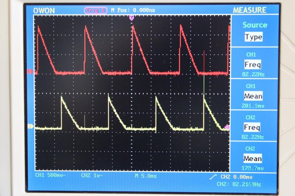
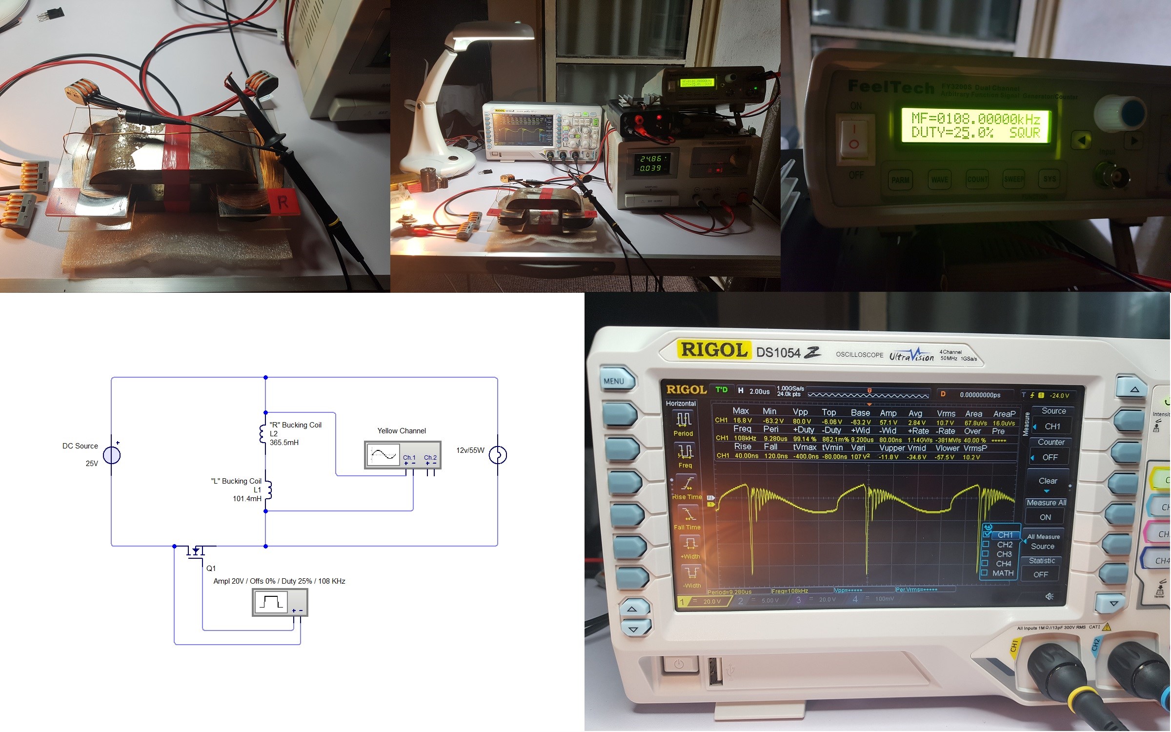
Chris's Non-Inductive Coil Experiment

  • Topic Is Sticky
  • 29K Views
  • Last Post 04 July 2023
Chris posted this 08 October 2019

My Friends,

I am going to show a small experiment, one that follows the works of Andrey Melnichenko and even Tariel Kapanadze's works and as we know many others.
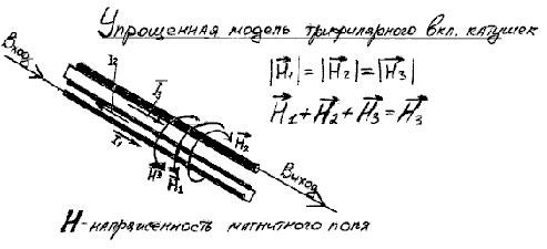


We have discussed here before, the fact that H3 is H3 simply because H1 and H2 cancel out: H1 + H2 + H3 = H3, why is this so, because H1 is Positive and H2 is Negative! We have seen this equation before: 1 + -1 + 1 = 1.

I think with Fighter's success recently, its time for some hands on!

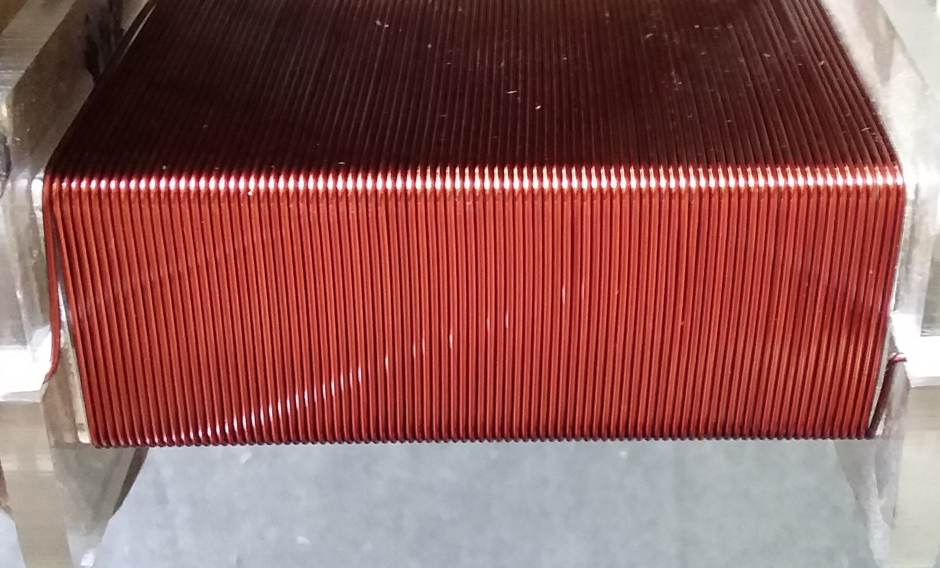
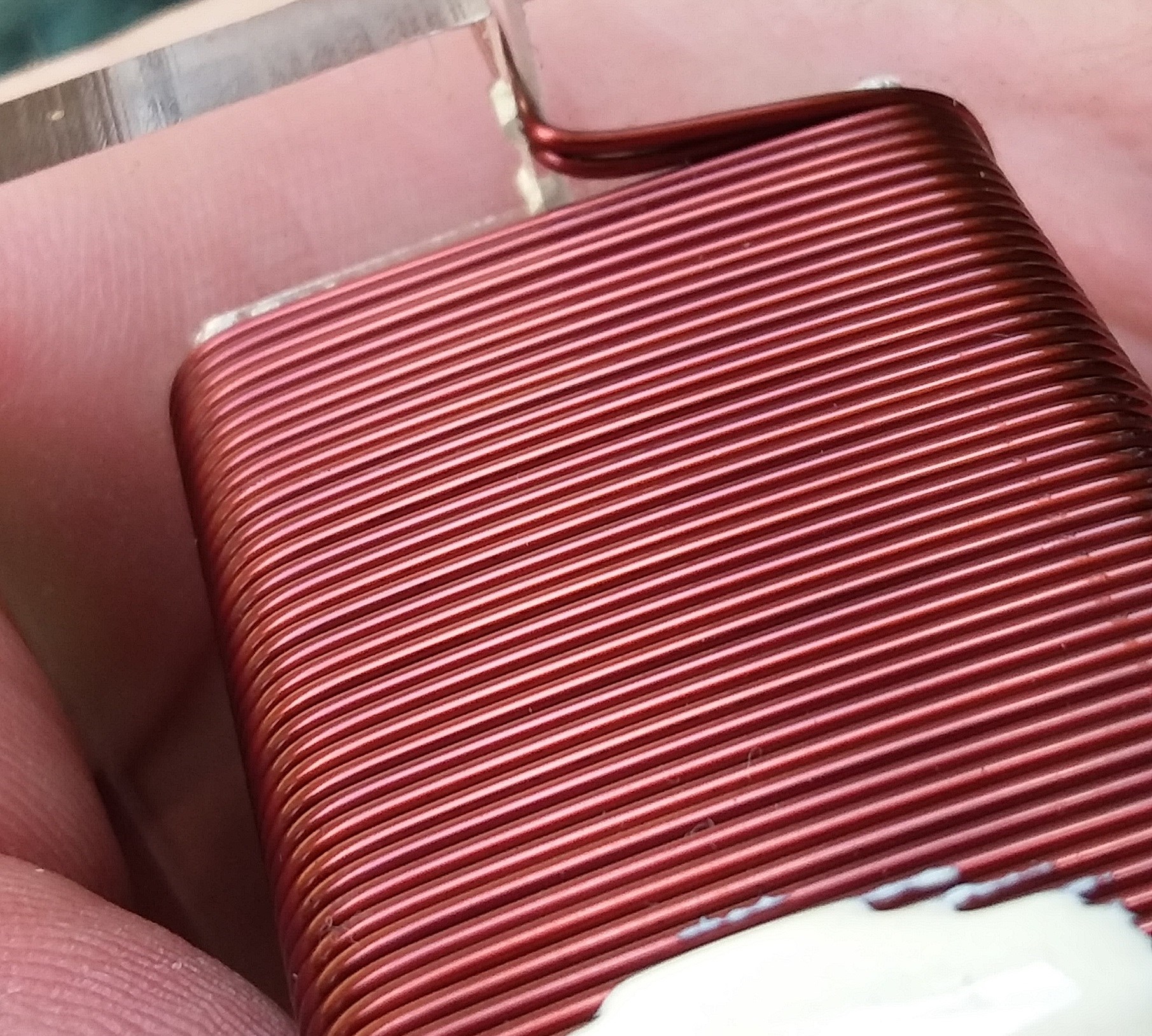
  • First Layer: 88 Turns.
  • Second Layer: 43 Turns.


Layer One:


Layer Two:
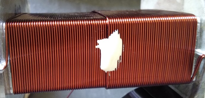
 

Turns Direction:
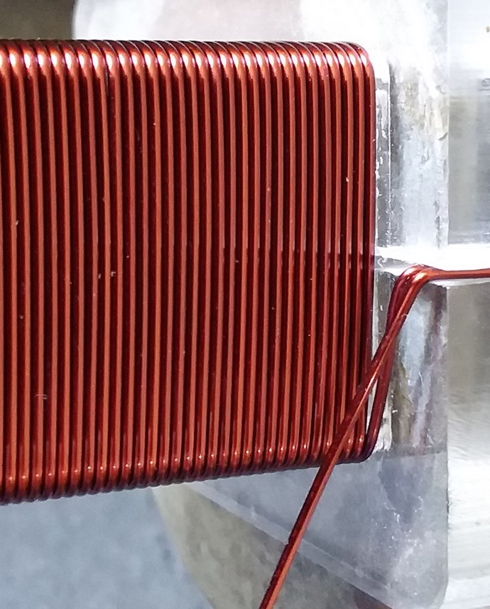
 

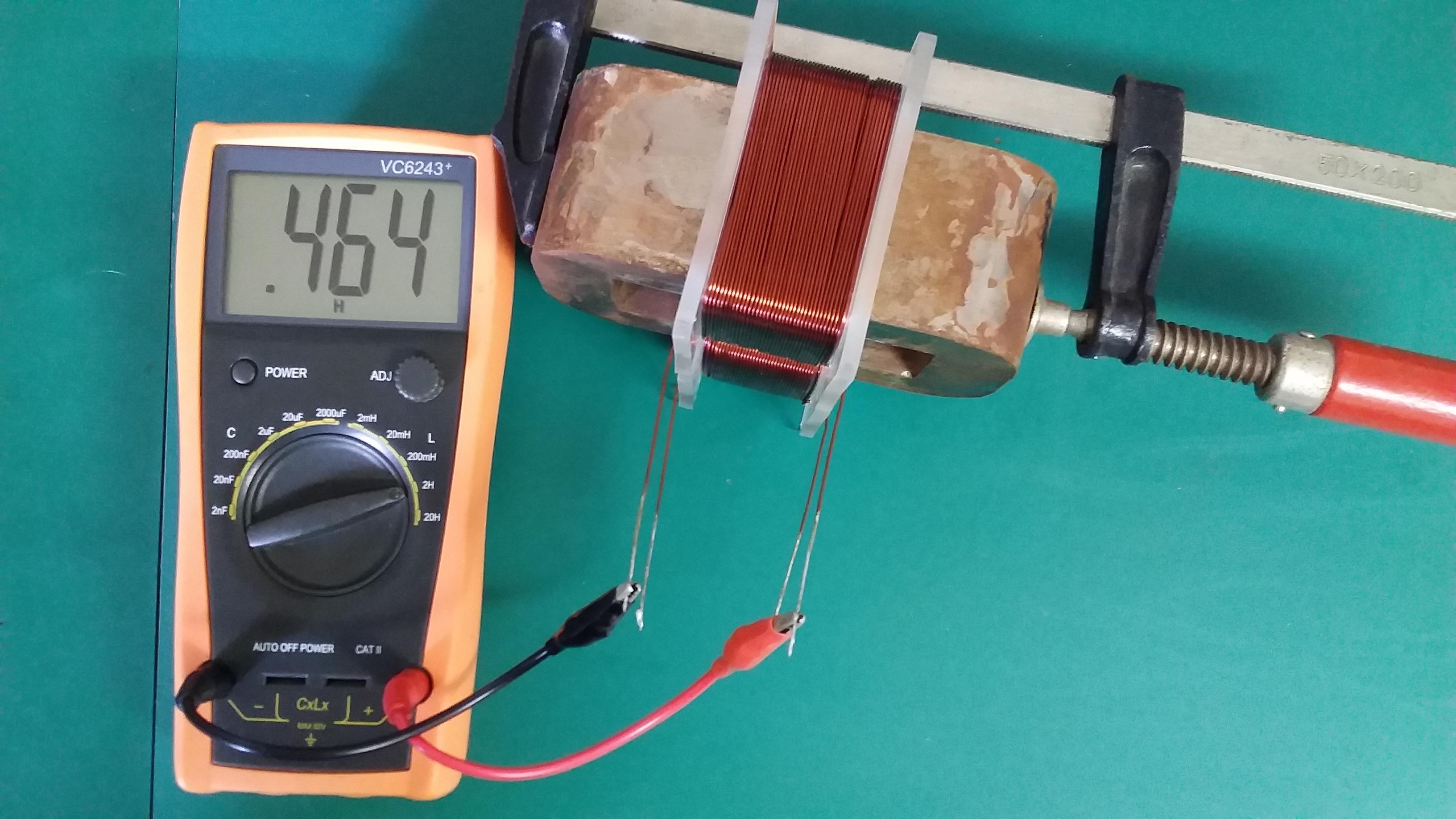
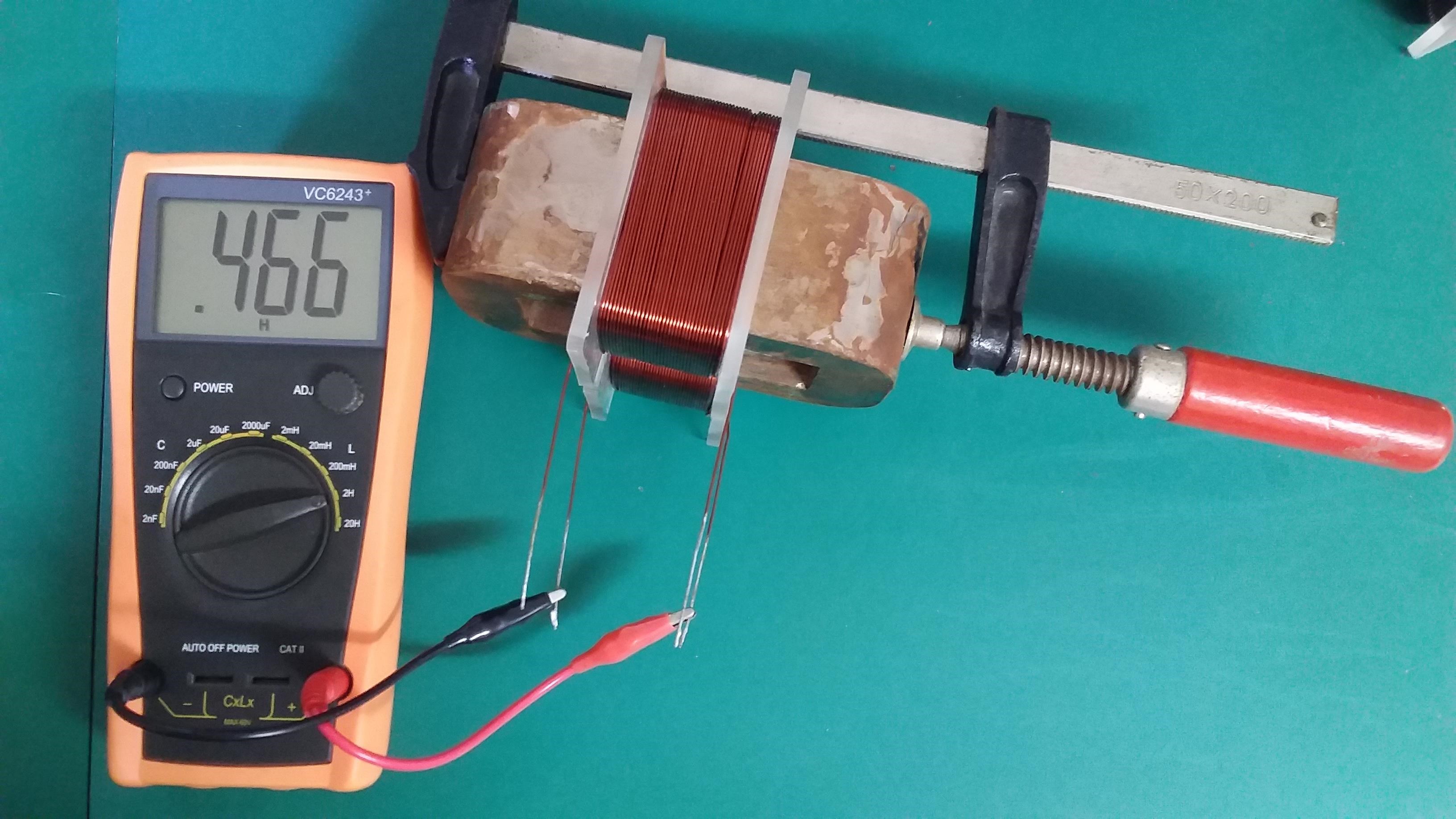
Layer One Inductance:
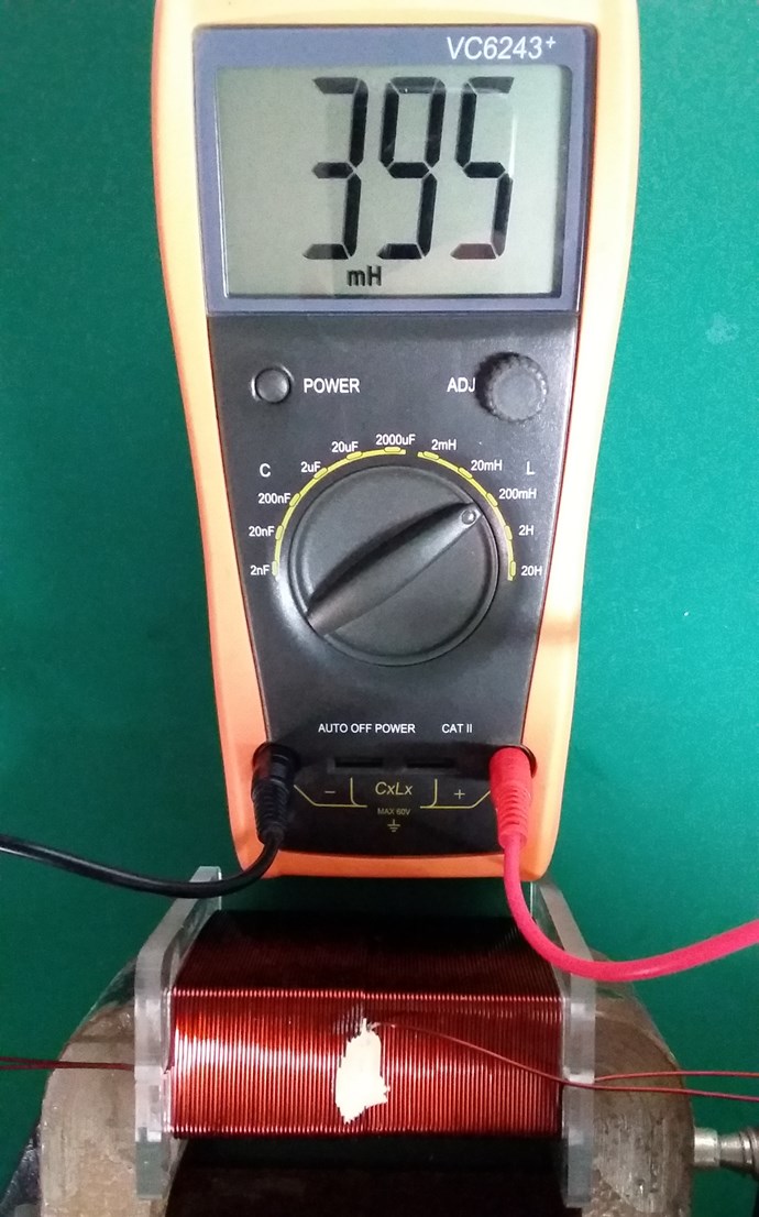
 

Layer Two Inductance:
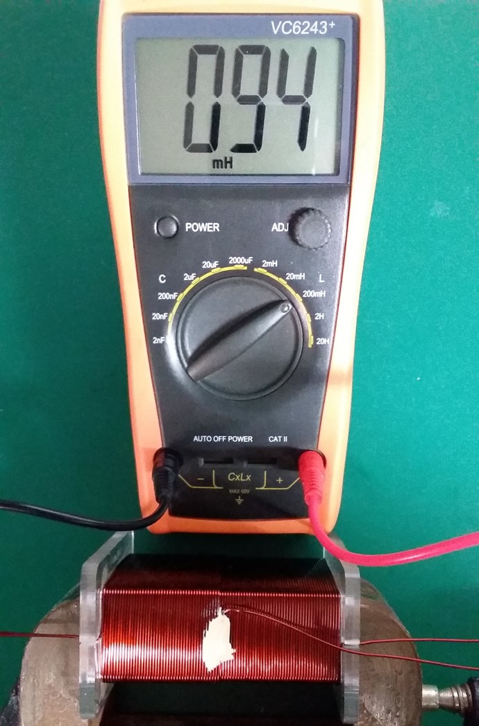
 

Non-Inductive Connected:
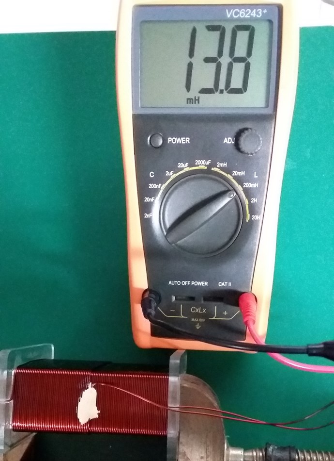
 

Layer One Resistance:
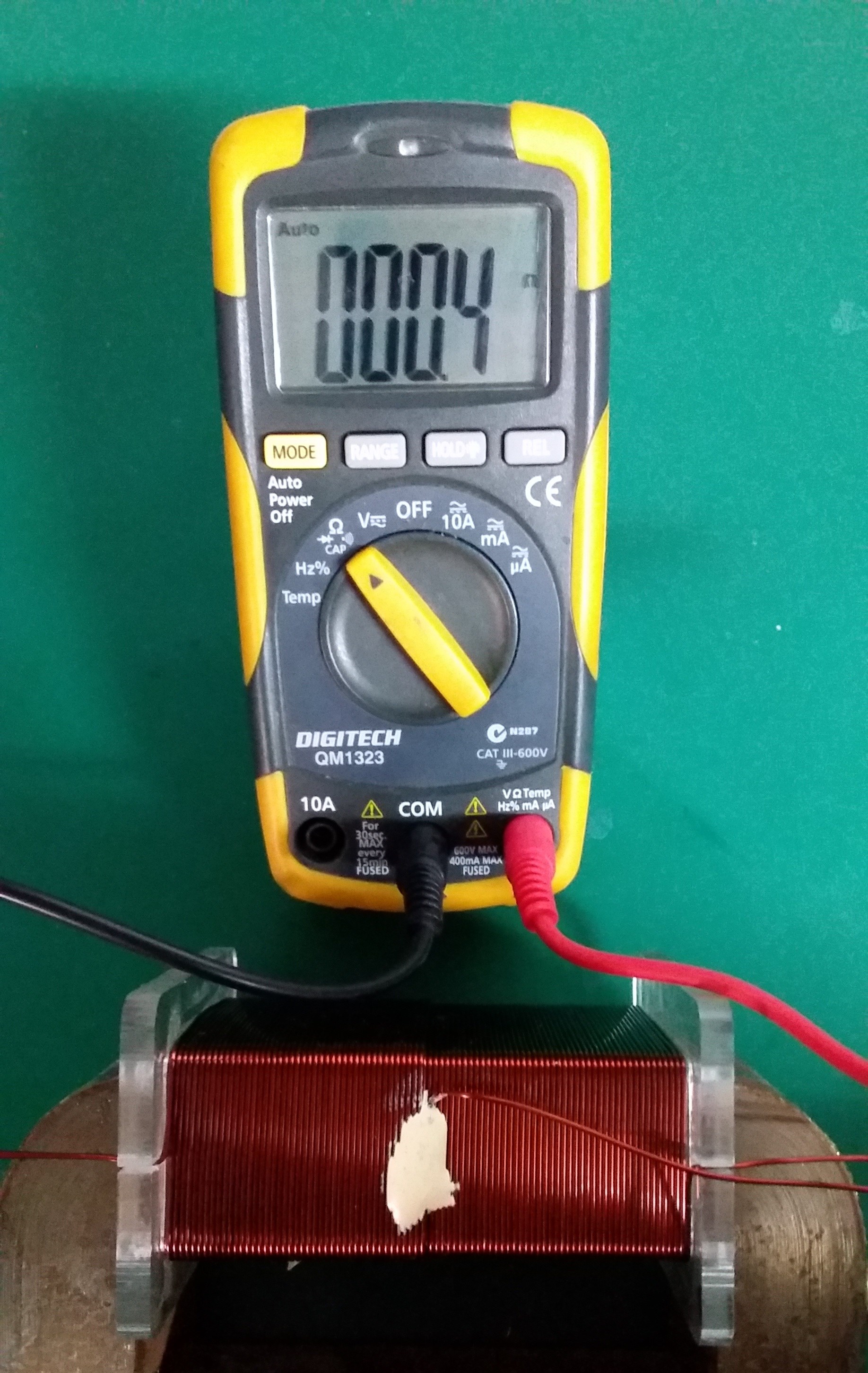
 

Layer Two Resistance:
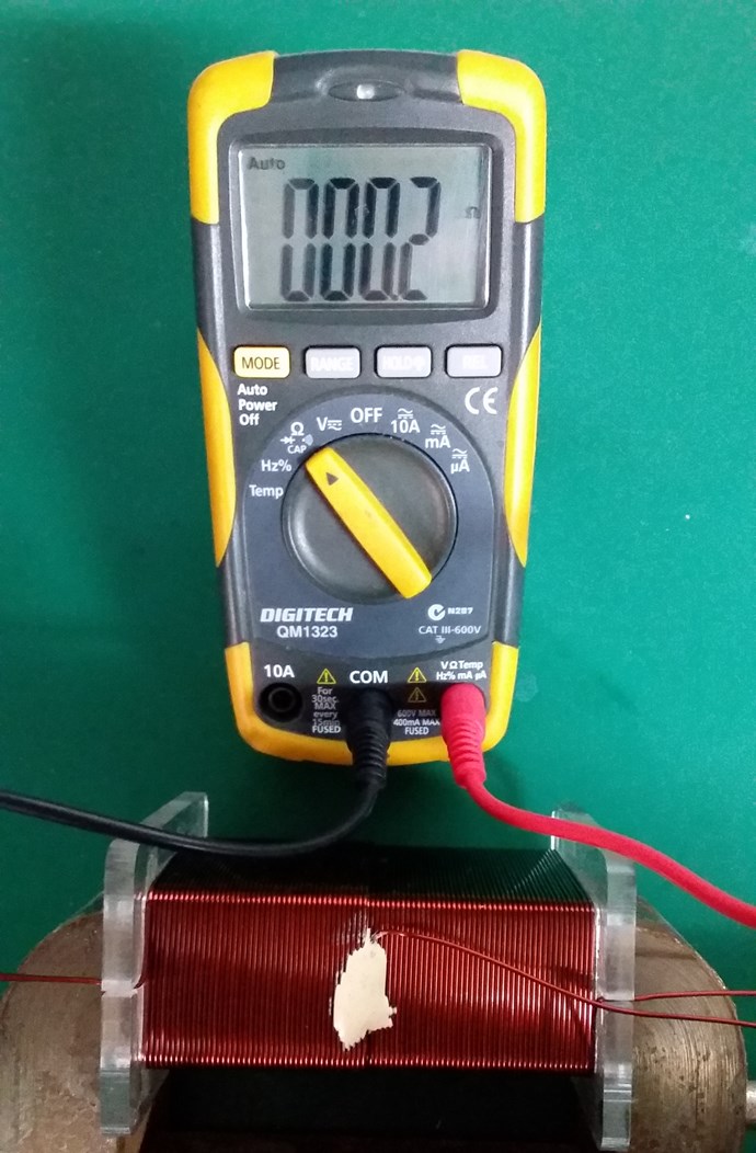
 

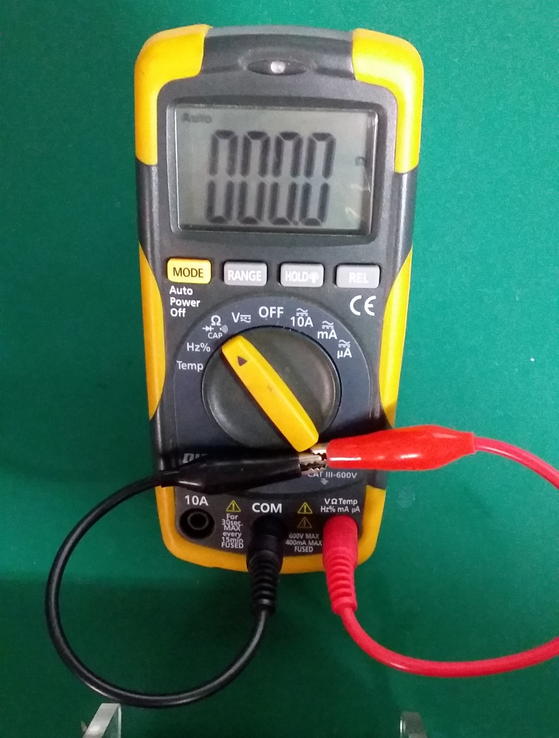
Closed Loop Resistance:
 

My Coil, like Andrey Melnichenko's, is 0.33 + -0.33 + 0.33 = 0.33.

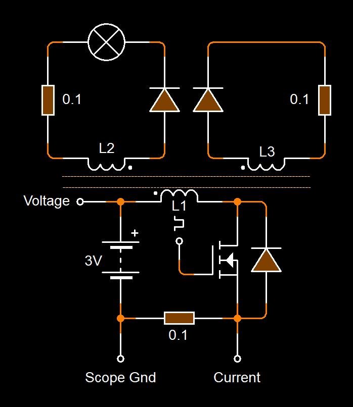
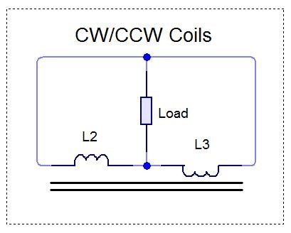
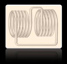
Two thirds of my Coil is canceled out. My Circuit looking like this:
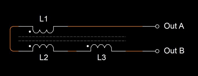
Where:

  • L1 and L2 are Non Inductive.
  • L3 is Inductive.


If this Coil is carrying 1 Ampere of Current, and exactly one half of the Coil is Non-Inductive, then Turn for Turn, only 45 Turns will create an M.M.F, which is considered as 45 Turns x 1 Ampere = 45 Ampere Turns or 45At.

Science tells us, that Turn for Turn, where we have Non-Inductive part of the Coil, this part of the Coil does nothing! Creates no Magnetic Field, therefore does nothing.

However, from Experiment, we know that this part of the Coil DOES do something! Remember Floyd Sweets paper: Nothing is Something, this is the same!

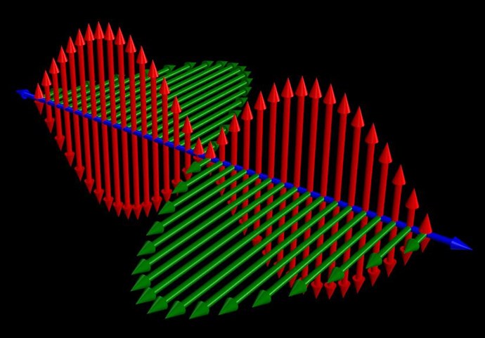
At Resonance, we have a perfect Standing Wave! We know this as Magnetic Resonance! Where each Magnetic Field is 180 Degrees out of phase:
 

Now, straight away, we should see a problem! Why? Kirchhoff's Current Law says the Current must be equal at every node, but we have Turn for Turn, one Coil that is Inductively Zero, and another Coil that has only a part of the Induction canceled!

In the specific case of positive charges moving to the right and negative charges to the left, the effect of both actions is positive charge moving to the right. Current to the right is:

I = da+ / dt + da- / dt

Negative electrons flowing to the left contribute to the current flowing to the right.


Each node does not equal the other, so the Circuit must balance out, Current is Increased as the Standing wave shows us.

Remember what Induction is? See here: Non-Linear Inductance

Induction gives us an approximation on the Coils ability to carry a Current: L = ε / di / dt

By Bringing a Coil arrangement like this into Resonance is our task.

Where each Electromagnetic Wave travels in opposite directions. One through the other in the same space.

THE NATURE OF SPACE

Space itself is the ability to accommodate energy. Consider for a moment the following illustration:

A signal (energy) is transmitted from point A to point B. A and B are separated by a finite distance. Consider three periods of time:

  • The signal is launched from A.
  • 2) The signal resides in the space between A and B.
  • 3) The signal arrives at B.

If (3) occurs simultaneously with (1) we say that the signal has traveled at infinite velocity. The signal has never resided in the intervening space and therefore there exists no space between A and B. A is virtually at the same point in space as B. For real space to exist between A and B it is necessary that a signal travelling between them be "lost" with reference to both points for a finite period of time.

Now we know that for real space to exist between two points a signal travelling between them will propagate at a finite velocity c, ( c = 1 / √με )

If a signal will not travel between two points, as in the case when c = 0, then we can also conclude that there is no link or intervening space between them. 

Ref: Floyd Sweet - Nothing is Something.


Floyd Sweet tried very hard to make c = 0! What does this mean? It is simply a Standing Wave, a Team Wave was used:

It is a simple matter using the equations E / H = √με and c = 1 / √με for a team wave to get rid of H and c and so convert the first equation into the well known equation for energy density in the so-called electrostatic field.

Ref: Floyd Sweet - Nothing is Something.


I have pointed out: Why 'C' is equal to One in these Devices.

We have a lot of data!

   Chris

Order By: Standard | Newest | Votes
Chris posted this 05 March 2020

Hey Ourbobby,

You should be very proud! We all have to start at the start, and your enthusiasm and dedication is something to be admired! Stick at it, you will get there.

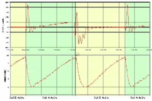
The Sawtooth Waveform comes from the magnetic Interactions:

Each Coil has a job to do. Each Coil produces a series of Action Reaction Pairs.

The Actions are:

Action, Reaction and Counter-Reaction


So, the Input Coil Induces a Voltage on the Partnered Output Coil One, POne, POne then carry's a Current because it is Loaded. This is the Action, Input Coil, and the Reaction Secondary Coil.

The instant POne starts to Carry a Current, Partnered Output Coil Two, PTwo has an Induced Voltage because of this change in Current on POne, the Diode starts to Conduct and a Current Flows. This is the Counter-Reaction. The Current in PTwo must assist the Primary Current and also must Oppose POne.

This process occurs in this period:


During this period, the Coils have very little Impedance, because each Coil this process occurs when the Coils Resonance point is found, and has the same effect as my experiment Reduced Impedance Effect.

Once this is done, we achieve a very Slapping together of the Magnetic Fields, we see a Voltage gained and Both Coils carry a Current. This is seen as a very slow Decay, a Sawtooth wave, because out Input is off, and the Partnered Output Coils now Pump Current for the remainder of the period:

Ref: Chris - Aetheric_Mind bucking coil experiment


Be proud my friend, hold you head high, you are like everyone else here, a part of History!

Best wishes,

   Chris Sykes

  • Liked by
  • cd_sharp
  • Fighter
Chris posted this 07 March 2020

My Friends,

We have covered this before, in many different places, but I am getting to a point here, soon.

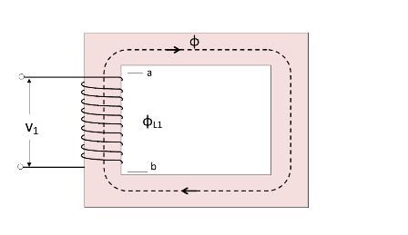
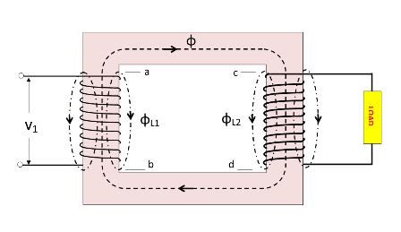
Every Transformer has a perceived Flux Direction, normally indicated by arrows:


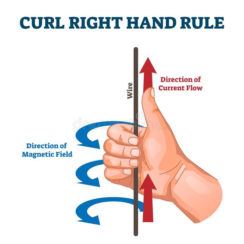
The Arrows in the Flux is given by the Right Hand Grip Rule and the Applied Conventional Current. It is never pointed out, that the Secondary Flux, from 0 to 90 degrees, is Equal and Opposite, North Pole Opposing North Pole. So Magnetic Flux is equal and opposite.

Flux Leakage in a Non Unity Coupled Transformer indicates this Opposition:

If you observe the arrows, you can see the arrows Oppose. The Secondary Flux, this is important so please pay attention, but the Secondary Flux, Changing in Time, is a critical aspect of a Transformer! This Flux is what regulates and determines the Conservation of Energy Law. Its the "Your'e not going Above Unity", regulator!

This Secondary Flux, Changing in Time, is what gives us the opportunity to "Generate" a Voltage and therefore a Current, in a Tertiary Coil.

Please think about this, its really important!

A Tertiary Coil will Assist the Primary Coil but will Oppose the Secondary Coil, so we have a total Assist, M.M.F is Positive in the System. 

Recently I posted this, to help Aetheric_Mind:

Each Coil has a job to do. Each Coil produces a series of Action Reaction Pairs.

The Actions are:

Action, Reaction and Counter-Reaction


So, the Input Coil Induces a Voltage on the Partnered Output Coil One, POne, POne then carry's a Current because it is Loaded. This is the Action, Input Coil, and the Reaction Secondary Coil.

The instant POne starts to Carry a Current, Partnered Output Coil Two, PTwo has an Induced Voltage because of this change in Current on POne, the Diode starts to Conduct and a Current Flows. This is the Counter-Reaction. The Current in PTwo must assist the Primary Current and also must Oppose POne.

This process occurs in this period:


During this period, the Coils have very little Impedance, because each Coil, this process occurs when the Coils Resonance point is found, and has the same effect as my experiment Reduced Impedance Effect.

Once this is done, we achieve a very hard Slapping together of the Magnetic Fields, we see a Voltage gained and Both Coils carry a Current. This is seen as a very slow Decay, a Sawtooth wave, because our Input is off, and the Partnered Output Coils now Pump Current for the remainder of the period:

Ref: Aetheric_Mind bucking coil experiment


Working with, and modifying the Transformer Force, as M.M.F, or Ampere Turns, NI, the Force directed back on the Primary Coil is critical to think about in the form I am trying to point out.

You can probably understand why we need a Load on the System to make this all work.

   Chris

Ourbobby posted this 08 March 2020


hi guys,

             Got part of the way today. Setting up dual voltage points, set up simple current limiter for mosfet current, got current showing  on scope but no sawtooth yet. I have blown my 3524 too. I think the  10%- delay should help to give me sawtooth, have a couple of 3524's on order. Have rewound the whole set of coils. using 76,76,19!. I wonder if I have wound the primary wrong direction over L2? Have 2 Cw wound coils.


Regards

ourbobby


direction?

  • Liked by
  • Chris
  • cd_sharp
Chris posted this 08 March 2020

Hey Ourbobby,

Can you please draw a Circuit and show where your'e Probing in the Circuit. I can only guess.

Your switching does look much better, is it reliable now?

Thanks for sharing!

Best wishes,

   Chris

  • Liked by
  • cd_sharp
Ourbobby posted this 08 March 2020

Hi Chris,

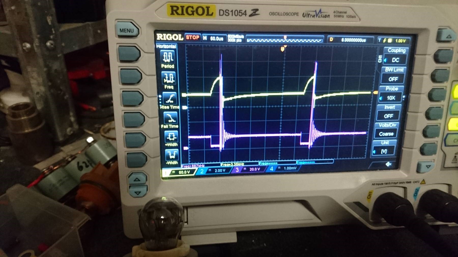
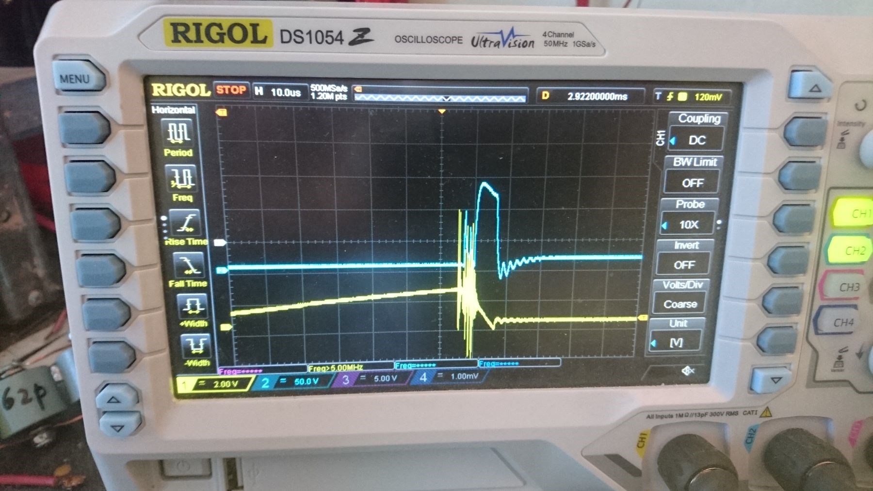
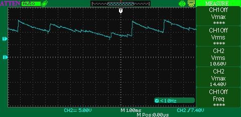
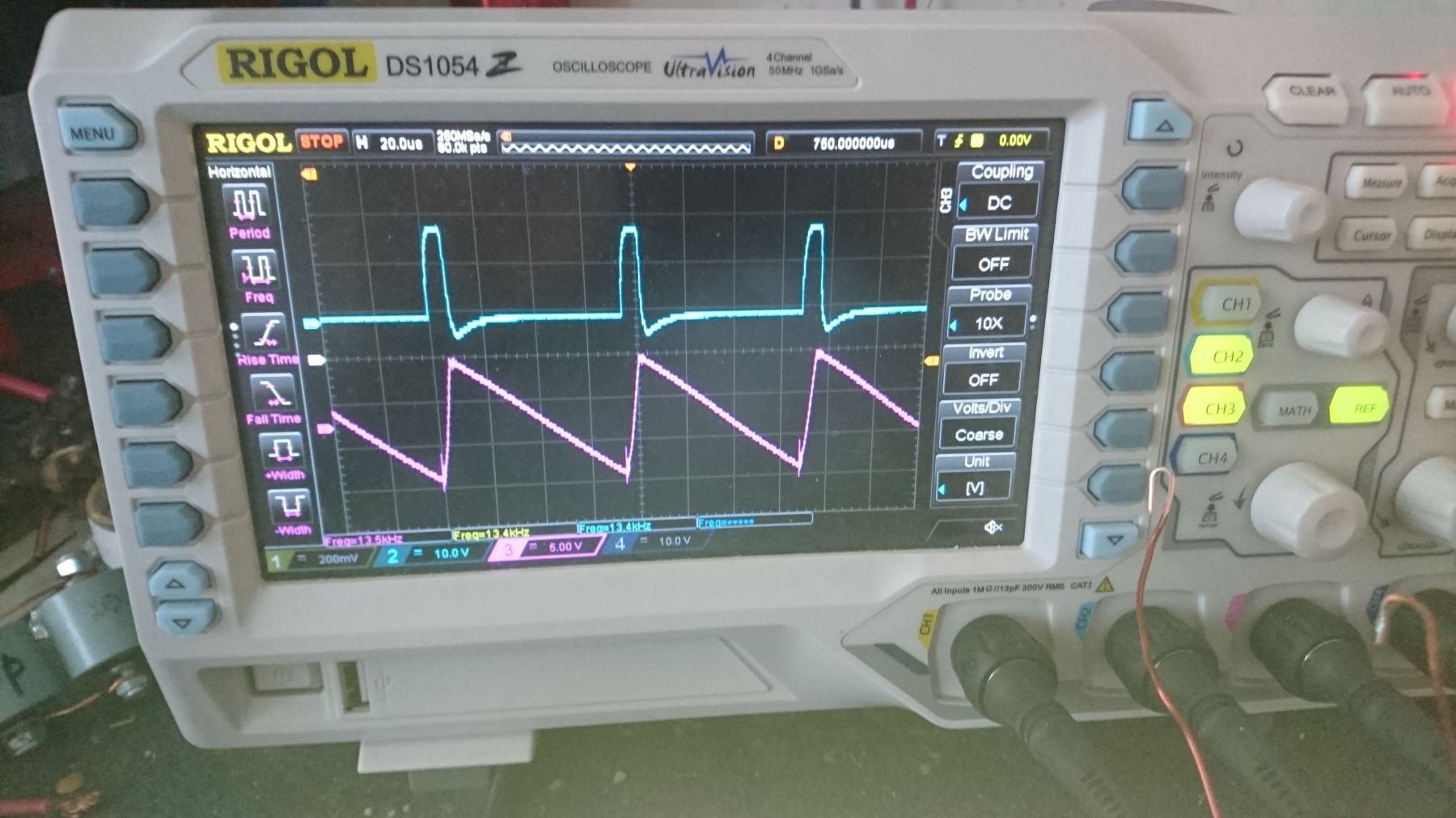
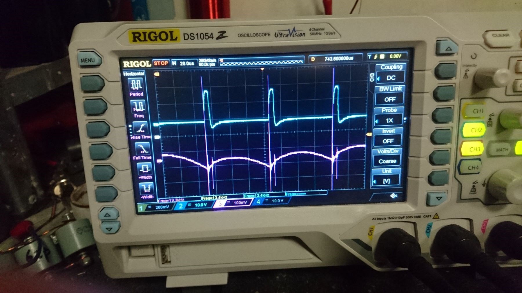
               I am probing where you are probing in Video 7. On my scope photo, yellow is input and violet is across 0.1 resistor of the L3 coil. Although, I am showing less than 10% duty cycle above, I just adjusted the screen to get a clear picture. Unlike previous attempt, same set up different outcome! I might try Don's reduction by a couple of turns on one of the coils to see if that helps. With L2 and L3 wound oppositely, I cannot see how winding direction of primary would make a difference, it would just mean left or right through the core? As you say the emphasis is between the slapping of two coils slightly out of phase with each other. 

Regards

ourbobby


  • Liked by
  • Chris
  • cd_sharp
Chris posted this 08 March 2020

Hey Ourbobby,

Re:

I am probing where you are probing in Video 7. On my scope photo, yellow is input and violet is across 0.1 resistor of the L3 coil. Although, I am showing less than 10% duty cycle above, I just adjusted the screen to get a clear picture. Unlike previous attempt, same set up different outcome! I might try Don's reduction by a couple of turns on one of the coils to see if that helps.

Ah ok, cool. perhaps we should all try to get into the habit of posting a Circuit with Test Points marked. This is a very Scientific approach to what we are doing and also helps to avoid Confusion.


Re:

I cannot see how winding direction of primary would make a difference, it would just mean left or right through the core?


My Thread: Some Coils Buck and some Coils DONT, will help you understand the difference between Coil Direction and also output Differences.


Re:

As you say the emphasis is between the slapping of two coils slightly out of phase with each other


Yes, this, I call Delayed Conduction, it is to help get the Voltage Up in the Coils. Other methods also exist, I hope to cover them soon also.

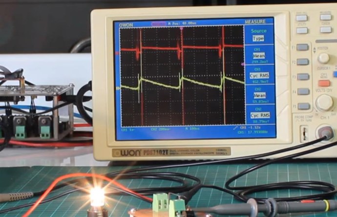
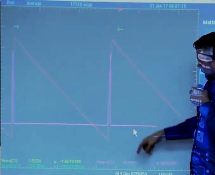
Ourbobby, excellent work, and Thank You for sharing! However, your waveform's are still not right. We need to help you a little more, to maximise the effects of the Coils Slapping together, then the long, Linear Decay Period:


Now, Load is Important, make sure you don't load down your machine too much! Make sure you have Voltage and Current on the Output. If you load your machine too much, it also chokes off the machine. The Coil / Magnetic Field Interactions are reduced, the Machine becomes a simple Transformer. Below Unity will be all you can get.

Best wishes, and Thank You for sharing!

   Chris

  • Liked by
  • cd_sharp
Ourbobby posted this 08 March 2020

Have just reduced the turns on L3 to 74. What appears clearly is a shift in outputs. I made a mistake in previous post. Yellow, very messy feedback, is across L3 and Blue is input! Getting there slowly. very small sawtooth! Losing the current  somehow.


Regards

ourbobby


  • Liked by
  • Chris
  • cd_sharp
Chris posted this 08 March 2020

Hey Ourbobby,

The Circuit is not right.

I would keep the turns you have, not make any turns adjustments, but check the Circuit. Youre not getting the right Magnetic Field Interactions.


This circuit, making sure L1 opposes L2, and L3 Opposes L2, which must mean L3 Assists L1.

Best wishes,

   Chris

Ourbobby posted this 09 March 2020

Hi Chris,

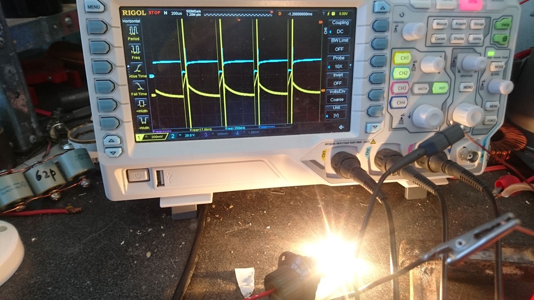
Well I have a result of sorts! And as you say on the videos, its all about the current. In your test you use a constant current of 100ma. At 3v this is 90mW, and at 12v you are 1.44W. So I have emulated those figures and get a sawtooth of sorts. as the scope shows at 12v, a sawtooth of sorts. And a shining bulb. I had to increase my constant current to 15v 200ma to get this result. This is a new wind! 1 coil 220turns 18awg, 1 coil 224 turns 18 awg and 1 primary using speaker wire 12 guage 16 turns - all I could fit onto the spool! So my resonance is well out with at 1/12.5 wave input. I need to understand what is going on and will have to think about the best approach, and considering how best to extract the energy. One interesting observation. The unit had been running for a few minute when all of a sudden, the globe "popped" on!!!


I had changed to the configuration you show above without any change to my outputs. This is when i decided to increase the coil sizes.

thanks for the encouragement

ourbobby

. I think I can see
Chris posted this 09 March 2020

Hey Ourbobby,

Starting to look much better! Thanks for Sharing!

As you increase the operation, improve your Machine, you should get a more Linear Sawtooth Waveform:


How Sawtooth your waveform is shows how much Opposition you have between the Coils, its Lenz's Law, we saw this here. Pardon the pun!

This stuff is Important, redirecting the Magnetic Fields like this, it the first step to making your Machine do work, well outside your Machines Input Period! When you can have 10% on time, then 90% work outside your Input, then that's plenty of time to "Generate" excess Energy when your Input is Off, a critical feature for Energy Machines!

Best wishes,

   Chris

  • Liked by
  • Fighter
  • cd_sharp
raivope posted this 09 March 2020

Hi Chris,

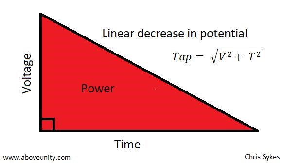
You have 10% ON and 90% OFF in input. I have seen this power triangle explanation, but don't you think that in 10% you have already paid for what is happening in the rest of 90%?

Someone tested some Melnichenko patent (some LCR circuit) and figured out that 1/4 (quarter) pulsing was beautiful - looks like you have 3 rising waves during ON and the rest 10+ are at decline. Measuring input and output (on resistor R) - revealed that there was nothing there.

resonance-illusion

You have to measure input and output on resistive load, wave shape does not give you full info. Of course - wave shape shows you if you have ferro/wave/accousting/stochastic/whatever resonance.

(If you find this msg inappropriate for this topic here you can delete, no prob)

Raivo

Ourbobby posted this 09 March 2020

Hi Chris,

              I am a little perplexed with the use of the term asymmetry. Asymmetric implies an unbalanced state. with the current topic, when using the three coils we have a primary and then L2 and L3. If we take the 4:1 Tesla ratio, as say per Don Smith, this implies that primary and say L2 are paired. To get to the equation, visualised with the slapping waves, L3 has to be a different ratio again. In the wave video, the returning wave would have depleted energy, but is the resistive force against the incoming charged wave. Therefore creating the clash.  Obviously, the returning wave has to be in the correct position returning for the slapping to be amplified. Therefore, in terms of the coils, which one is the returning wave? L3? if L2 is wound with primary. Is L3 wound with different number of turns?

The coils in the tests shown in the set of non-inductive coils, other than video 1, all others would seem to be equally wound.

Regards

ourbobby


  • Liked by
  • cd_sharp
  • ISLab
Chris posted this 09 March 2020

Hi Ravio, My Friends,

This post is very Important! Please read and understand!

What you bring up has valid points!

You have 10% ON and 90% OFF in input. I have seen this power triangle explanation, but don't you think that in 10% you have already paid for what is happening in the rest of 90%?


In all conventional Transformers, Energy is Transformed, Input is Transformed to Magnetic Force to Output Force, the M.M.F, or Ampere turn is equal and opposite less losses. Input M.M.F is Equal and Opposite to the Output M.M.F less Losses! Any time you offset the M.M.F, force, then you have more work in the System. 

This is the point of the Machine we build, to Offset the Input to Output M.M.F, to add M.M.F via the Third Coil!

Yes, it can be that these Waveform's can have Conventional Transformer Transformations, but we are not building a Conventional Transformer, that's the point of what we are doing.

Someone tested some Melnichenko patent (some LCR circuit) and figured out that 1/4 (quarter) pulsing was beautiful - looks like you have 3 rising waves during ON and the rest 10+ are at decline. Measuring input and output (on resistor R) - revealed that there was nothing there.


A great deal of experiments performed by others are invalid, until one understands the Subject matter and thus the foll operation of a machine, experiments can be completely inconclusive! I have done many experiments that I look back on and think to my self, there is no way that could have worked, I did not understand the machine, if the slightest deviation in the Experiment you are performing from the original experiment, then the experiment is wrong. So we really can not compare unless we have everything 100% Correct and can verify that.

Th waveform you show, is not like any Andrey Melnichenko Experiment Waveform I have ever seen and thus can not comment on its validity or verification.


You have to measure input and output on resistive load, wave shape does not give you full info. Of course - wave shape shows you if you have ferro/wave/accousting/stochastic/whatever resonance.


I always use Resistive Loads, an Incandescent lamp is largely a Resistive Load, this means Power is real, Voltage and Current are in phase - Yes.

It is correct to ask questions! No one should believe what might be ramblings of a crazy person! I expect all members to question everything, after all that's our job, in Research, is to question everything, until we understand it, totally and fully!

The Sawtooth waveform can be both Below Unity and Above Unity! Some examples I have given here on this forum, Don Smith, The MEG Team, Graham Gunderson, Tinman aka Bradley Richard Atherton:


The Sawtooth Waveform is the Defining Lenz's Law Waveform!

I pointed out in my thread: Some Coils Buck and some Coils DONT why the Sawtooth Waveform is so important:

The Sawtooth Waveform is the Result of Lenz's Law, the very fact that Two Magnetic Fields are working together! This Magnetic Field Interaction is CRITICAL to understand! It is the EXACT Same effect as dropping the Neo Magnet down the Copper Tube:


This is the reason the waveform has a Linear Decay, not an exponential decay! A Critical fact to observe and understand! 

The Sawtooth Waveform is the Defining Waveform for Energy "Generation"!

Best wishes,

   Chris

  • Liked by
  • ISLab
Ourbobby posted this 10 March 2020

Hi Chris,

              Let me see if I understand what you are saying about the Lenz. We are not concerned with cancellation of energy due to symmetrical impact of L2 and L3 output. We are concerned with seeking the point the Lenz kicks in almost simultaneously on L2 and L3. The slapping effect we are looking for is joining two current and two voltage conditions using a very small window of delay between the outputs of the two coils. What Don Smith states is just a couple of turns on one of his pairs of coils.

Thanks for the explanation

ourbobby

Chris posted this 10 March 2020

Hey Ourbobby,

Technically, Lenz's Law predicts the Direction of, or Polarity of the Voltage that is "Generated". However, as we think of, and deem Lenz's Law, as the Drag on the Rotor, of Back E.M.F in the Transformer, which is technically incorrect.

The Magnetic Field, implied by the Voltage Polarity, is the Problem!

What constitutes a magnetic Field? Current! Yes, for example, no Current Flow in a Coil, the Coil produces no Magnetic Field!

This means, we need, we must have Current Flow, therefore we Must have an associated Magnetic Field! There is no way around this, one is the other! The answer is, what we do with this Magnetic Field! So we now know, each and every Coil that has a Current, must have its own associated Magnetic Field. We have covered this here many times!


IMAGINE: We have a Transformer, it has 2 INPUTS, 1 Output. Inputs are both in phase, they add together! Our Output is loaded, it has 100 Watts Loaded. One Input we pay for, one we don't, one Input is 50 Watts and this costs us! The other Input is not, its powered from a Solar panel, or any other form of Power, but it to is supplying 50 Watts! Point being we are ONLY paying 50 Watts, the other 50 Watts is Free, we are not paying for that 50 Watts! Yet, at the Output, we have 100 Watts! 


The above scenario is, we have a Energy Input to our System that we ourselves are not paying for! We have an Input we are paying for! We have more Output because we have this extra Energy Input to the System. Our Third Coil is an Input to the System, adding Energy, Watts, Joules per second! It is seen as a Magnetic Force or M.M.F.

In our machine, we have 1 Input, 2 Outputs.


We Engineer Lenz's Law, so the Law itself, when used Asymmetrically, can give us a Gain in Energy.

Call me a Lenz's Law Engineer!

Ref: Partnered Output Coils - Free Energy


Best wishes,

   Chris

  • Liked by
  • cd_sharp
Ourbobby posted this 10 March 2020

Thanks for being patient with me! This is a good concise explanation. 

ourbobby

  • Liked by
  • Chris
  • cd_sharp
Chris posted this 10 March 2020


Thanks for being patient with me! This is a good concise explanation. 


Hey Ourbobby,

We can only do this together my friend!

I often over look things, not realising others may not see things the way I do. We are all filled with the same colour blood, the same DNA!

Together we can achieve unlimited possibilities!

Divided, we are very limited!

Power, Electrical Energy is the most basic fundamental aspect to a life free of unnecessary poverty and discomfort! Most discomfort and poverty is by design, so the top 1% can soar over every one else. I will be happy when the top 1% are in Jail for their crimes against Humanity!

Apologies, going way off topic now.

Best wishes,

   Chris

Chris posted this 12 March 2020

My Friends,

I really want to get more moving on the idea of Action, Reaction and Counter-Reaction of Coils. Aka Partnered Output Coils.

We Human Beings can become so much more! We only need make our mind up, put some effort in, and do the Experiments.


Please remember what Floyd Sweet said:


The source of energy is unlimited, the virtual vacuum of space itself structured by a motional electromagnetic field is the powerhouse.

Ref: Floyd "Sparky" Sweet Nothing is Something.


What is our machine doing? Yes it is Modulating the Magnetic Fields Asymmetrically.


I have had help, I can not explain it, but I can say I have had a hand guide me in the right direction. I ask that hand also guide others in the right direction, please.

I love this world, I love the life on it, I desperately yearn for Change, for every Human on the planet to become who we are supposed to become, we have so much more potential, we only need reach for it!

Thank You My Friends, both above and here.

Best wishes,

   Chris

Chris posted this 13 March 2020

My Friends,

For the sake of completeness, and accuracy, I want to share a little more data on my Last Asymmetrical System. My Inductance of each Partnered Output Coil:


Coil Turns: 254


You can see, each Coil is nearly Identical. Turn for turn, they should be the same, the Inductance just being localised differences. The DC Resistance is significant.

For most, this will not mean much, nor should it. What this information does say to us, is, to increase the Output, we need to reduce the Resistance, of course, the Coils Impedance will be even higher again, from tens of Ohms to several Hundreds of Ohms, the AC Resistance. Now you will see why we can not have too many turns!

Equations:

XL = 2 * pi * f * L, where L is the inductance in Henrys

XC = 1 / (2 * pi * f * C), where f is the frequency and C is the capacitance in Farads


This means, the Reactance is: 8749.7143Ω, now as far as I am aware, I understand this is for a Sinusoidal Waveform, we are not using a Sinusoidal Waveform, Its Pulsed DC.

Please do not over complicate this, it is so simple, and could not have more far reaching consequences!

Please everyone, we MUST Do this, we must ban together, the future of our race depends on us making changes right now, not tomorrow, but today, for what we do today can change tomorrow!

Best wishes,

   Chris

Chris posted this 14 March 2020

My Friends,

An Important Post today. Today, a Paradox, only explained in Experiment.

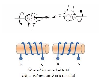
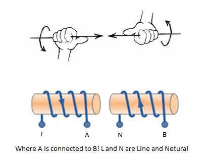
Any Electrical Engineer will tell you: "The way a Coil is wound does not make any difference to the System." This statement is not true. In my thread: Some Coils Buck and some Coils DONT, I gave experimental proof, the Winding Direction is important! 

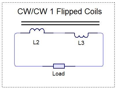
In this particular Circuit, Configuration Two in bucking mode appears to be the most beneficial! CW/CCW Coils.

  • 0.680 volts RMS
  • 192.1 ma mean
  • 196.4 ma mean

Compared to where Bucking does not Work, not very well anyway:

  • 0.587 volts RMS
  • 55.18 ma mean
  • -19.97 ma mean

and the next best configuration after Configuration Two, Configuration One:

  • 0.624 volts RMS
  • 150.9 ma mean
  • 172.2 ma mean


There are three configurations:

  1. Coils wound in a single direction in the same Axis.
  2. Coils wound in a single direction in the same Axis, but one Coil flipped End for End.
  3. Coils wound Clock Wise and Counter Clock Wise respectively in the same Axis.


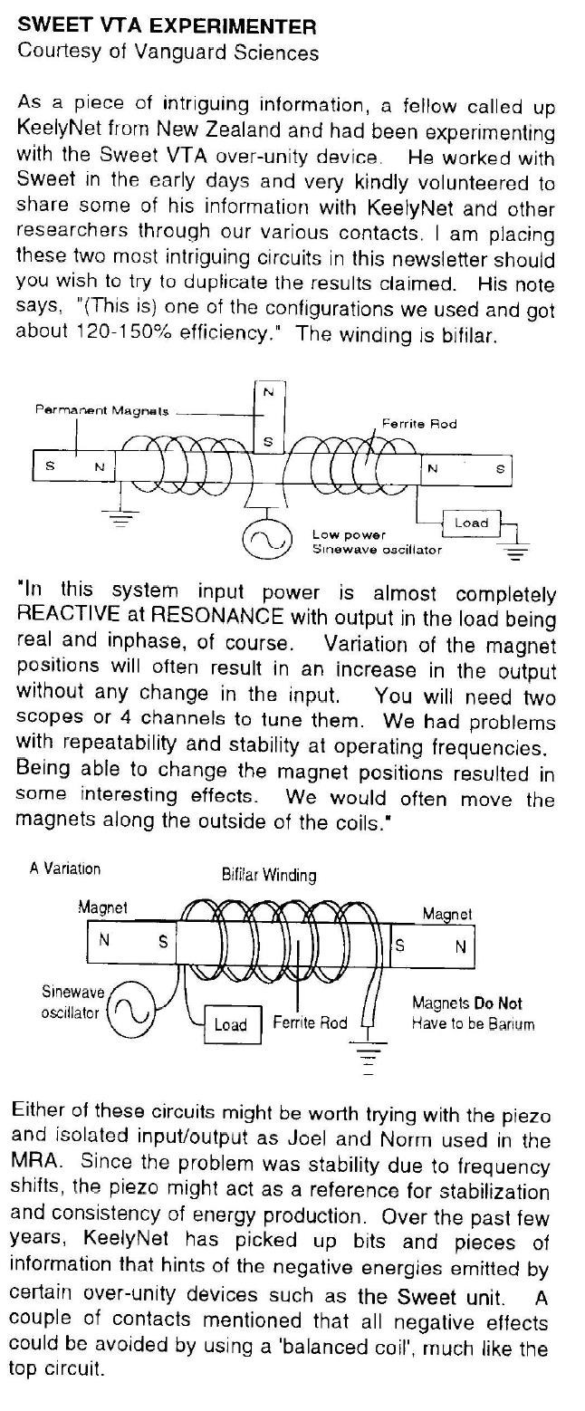
NOTE: We have detailed Tariel Kapanadze's Grenade Coil and how part of the Coil is Non-Inductive by Definition, yet it Amplifies Voltage and Current many times! COP = ∞

The experiments I have shown, show the same basic things as others before me have:


@9 : 46 in the following Video, Listen, the Noise is a giveaway!


The most simple experiments are the most important! Every single machine I have ever seen, the Inventors all started with studding the Electrical "Generator", all of them!

Akula, just before he got the Lanterns working: "ТПУ от акулы 0083 часть 2"


CLEMENTE FIGUERA

PRINCIPLE OF THE INVENTION - Watching closely what happens in a Dynamo in motion, is that the turns of the induced circuit approaches and moves away from the magnetic centers of the inductor magnet or electromagnets, and those turns, while spinning, go through sections of the magnetic field of different power, because, while this has its maximum attraction in the center of the core of each electromagnet, this action will weaken as the induced is separated from the center of the electromagnet, to increase again, when the induced is approaching the center of another electromagnet with opposite sign to the first one.

Because we all know that the effects that are manifested when a closed circuit approaches and moves away from a magnetic center are the same as when, this circuit being still and motionless, the magnetic field is increased and reduced in intensity; since any variation , occurring in the flow traversing a circuit is producing electrical induced current .It was considered the possibility of building a machine that would work, not in the principle of movement, as do the current dynamos, but using the principle of increase and decrease, this is the variation of the power of the magnetic field, or the electrical current which produces it.

The voltage from the total current of the current dynamos is the sum of partial induced currents born in each one of the turns of the induced. Therefore it matters little to these induced currents if they were obtained by the turning of the induced, or by the variation of the magnetic flux that runs through them; but in the first case, a greater source of mechanical work than obtained electricity is required, and in the second case, the force necessary to achieve the variation of flux is so insignificant that it can be derived without any inconvenience, from the one supplied by the machine. Until the present no machine based on this principle has been applied yet to the production of large electrical currents, and which among other advantages, has suppressed any necessity for motion and therefore the force needed to produce it.


The induced voltage in the winding obeys Faraday’s law as quantified by Neumann

Ref: Floyd Sweet - The Space-Flux Coupled Alternator.


Many others also! We have been told:


I am trying to tell you the same thing, I use reference to show I am only re-sharing something that others have already tried to share, at least in part.

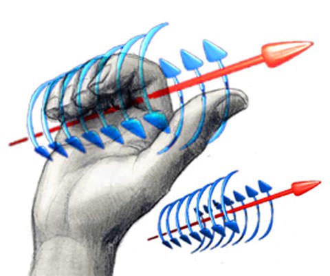
The point here is the Curl of the known Fields and how this Curl can be represented! To get some idea, about the Curl:


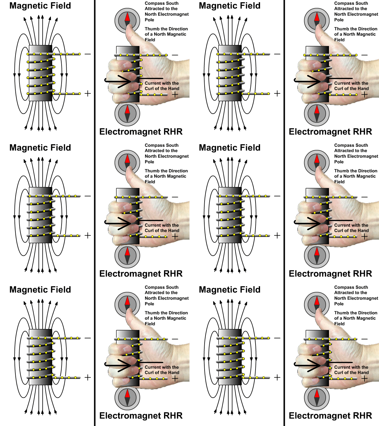
The Right Hand Grip Rule can be applied in a few different ways, to predict Current, or Magnetic Field and even the Magnetic A Vector Potential.We must move down the the Core Level, pretend we are standing on the Core and can see the Curl.
 

If we are smart, and we are, then we can apply Electromagnetic Induction to every single Changing Magnetic Field, the Primary and the Secondary, where normally the Secondary is ignored.

Remember what we were told:


That is such an important statement!

The Coils each have a Current, and if we work the Currents such, that the Currents themselves make for a greater Primary Assist, also meaning the Primary magnetic Field is Greater, then we have exactly as Floyd Sweet Told us:

The current and potential windings require relatively little power, and are applied in such a manner
that rate of flow of moving charges may be accelerated beyond 1 ampere = 6.24 x 10¹⁸ electrons per second. Thus the duty factor of the copper changes.

I2R losses diminish and more charges drawn from the now coherent space field flow at a faster rate as current to the load. This means as more current is required by varying loads more feedback magnetomotive forces free more electrons from binding forces complimented by potential magnetic forces of the orientated, coherent space field. Thus a conductor that formerly had a temperature rise above ambient labelled as a factor of 10 would now operate at a temperature of 1.0. Thus the same gauge wire would carry 10 times more current at the same temperature. 

Even better results may be forthcoming. The energy conversion conservation is fantastic.


Your Input Coil only brings the Potential, or Voltage up, The Partnered Output Coils do all the work themselves! One Partnered Output Coil being the Coil on the Stator and One Partnered Output Coil being the Coil on the Rotor, each Coil only being excited by the Action, in our case we are replacing the Rotation of the Rotor with a small Changing Magnetic Field initially.

We have built a Solid State Electrical "Generator" - This is the best way to think of it.


Your Core can only hold so much Magnetic Field, your Coils can only have so much Current through them.

Best wishes,

   Chris

Ourbobby posted this 14 March 2020

Hi Chris,

              i am suffering a bit from information overload! Arthur or Martha? Just help me out here please. Above you show measurments for two coils.  What I don't get is your meter showing 80+ ohms for impedance. How did you do that?


Regards

ourbobby

Chris posted this 14 March 2020

Morning Ourbobby,

I have a feeling my Digital Multi Meter is faulty, I am about to get another Meter and re-check the measurements.

For now, please disregard the DC Resistance of the Coil, I do believe, and Vidura as you have, has also pointed out this seems wrong.

"Little steps for little feet", please, the information will always be here, so don't worry, your experiments will give you answers.

Really, there is only three things you need to keep in mind:

  1. You need at minimum 2 Output Coils.
  2. Your Output Coils must Buck, or Oppose.
  3. Your Input is only a tickler, to get your Potentials, or Voltages Up.


All here can help so please try not to feel overwhelmed. I know its hard.

Best wishes,

   Chris

  • Liked by
  • cd_sharp
  • chocolate blanco
Ourbobby posted this 15 March 2020

Hi Chris,
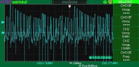
As you say, KISS is the acronym. I realise why I am having difficulty establishing, I need a controlled current power supply with an independent voltage adjustment to hold the set current. Without this, I cannot see a way forwards. I am able to get to see the current rise, but as soon as I raise the input power, I lose it. As soon as I overload the POC unit, I lose any semblence of current rise. That is, the window disappears. No sawtooth!! Also, I am getting a tremendous amount of noise and random looking waveforms. Again, I would suppose, correctly balanced coils, with the correct power input, and its happy days are here again!

There ia s lot of information on your Hyiq site. Constant refences and examples contribute to the difficulty of a successful build. in the short term at least. I am mindful oj John Bedini's approach which although implying"free Energy", did not seem to be threatening. People out ther clammered to his site and workshops. His working model, the SG for example would have enabled many hundreds, if not thousands of afficionado's!.

Anyway, I have to have a rest, the constant interrogation of your links and threads has exhausted me. until I can a solution I shall have to become a theoretical builder.

Regards

ourbobby

Vidura posted this 15 March 2020

Hey Ourbobby, It happens to all sometimes that we become saturated by a lot of information, anyway, the most valuable knowledge is that gained by experience. Regarding the inconvenience with your actual setup, if I may suggest: Try a simple experiment like the Mr Preva or the coils like in Chris' tread some coils buck and some coils don't, so you can evaluate if your switching unit is working correctly. A regulable lab power supply is useful, but not indispensable. Most experiments can be performed using batteries as well. Adjustment of voltage on some cases is needed, while the current limiting feature is mostly for protection of the equipment. If I can help with something just let me know. Vidura.

Ourbobby posted this 18 March 2020

Hello,
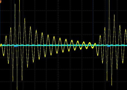
I do not have a variable AC supply to drive the Mr Preva or the non-inductive coils. I am not sure how to interpret the pulsed outputs due to obvious jittering or excess interference. I have tried tuning the non-inductive coils I have already wound. Approx 3000hz I get with a 105 capacitor. This is my output. Nice big sawtooth.

However, it seems I shall have to get a lab power supply of sorts so that I am able to control the inputs. At present, with a resistive load as the current control, my pulse at the mosfet changes in frequency as I increase voltage. As the power ratio changes. So although I set the pulse to 10%, at the mosfet output, it changes to relfect the power to the coils. Anyway, understanding this is good.

! can get a sawtooth this way!

Regards

ourbobby


Chris posted this 18 March 2020

Hey Ourbobby,

Awesome work! Much better than last waveform! There you have it, excellent progress! Improvement comes from work, with work, we see gains in Energy as the effects are improved! Very nice! Thank You for sharing!

I believe it is your turn to be added to the list, well done!

Best wishes,

   Chris

  • Liked by
  • cd_sharp
  • chocolate blanco
Ourbobby posted this 18 March 2020

Hello Chris,

                  I am yet to have the magic eureka moment! But, thanks for the comment. I must look for the output or energy input next.


Regards

ourbobby

Ourbobby posted this 18 March 2020

Hi , just before I head off to bed, I also have a primary winding on the core, so that I can look for differences between core winding and on top of L2 winding! Here is the difference for me. Which is the better route?

Regards 

ourbobby

Chris posted this 18 March 2020

Hi , just before I head off to bed, I also have a primary winding on the core, so that I can look for differences between core winding and on top of L2 winding! Here is the difference for me. Which is the better route?


Hey Ourbobby, Can you explain this further, I do not understand. Perhaps a diagram, might help me understand what you mean.

Re:

I am yet to have the magic eureka moment! But, thanks for the comment. I must look for the output or energy input next.


You have the interactions there to led you to a much greater understanding Ourbobby! Don't forget the waveform is a precursor:

Hi Ravio, My Friends,

This post is very Important! Please read and understand!

What you bring up has valid points!

You have 10% ON and 90% OFF in input. I have seen this power triangle explanation, but don't you think that in 10% you have already paid for what is happening in the rest of 90%?


In all conventional Transformers, Energy is Transformed, Input is Transformed to Magnetic Force to Output Force, the M.M.F, or Ampere turn is equal and opposite less losses. Input M.M.F is Equal and Opposite to the Output M.M.F less Losses! Any time you offset the M.M.F, force, then you have more work in the System. 

This is the point of the Machine we build, to Offset the Input to Output M.M.F, to add M.M.F via the Third Coil!

Yes, it can be that these Waveform's can have Conventional Transformer Transformations, but we are not building a Conventional Transformer, that's the point of what we are doing.

Someone tested some Melnichenko patent (some LCR circuit) and figured out that 1/4 (quarter) pulsing was beautiful - looks like you have 3 rising waves during ON and the rest 10+ are at decline. Measuring input and output (on resistor R) - revealed that there was nothing there.


A great deal of experiments performed by others are invalid, until one understands the Subject matter and thus the foll operation of a machine, experiments can be completely inconclusive! I have done many experiments that I look back on and think to my self, there is no way that could have worked, I did not understand the machine, if the slightest deviation in the Experiment you are performing from the original experiment, then the experiment is wrong. So we really can not compare unless we have everything 100% Correct and can verify that.

Th waveform you show, is not like any Andrey Melnichenko Experiment Waveform I have ever seen and thus can not comment on its validity or verification.


You have to measure input and output on resistive load, wave shape does not give you full info. Of course - wave shape shows you if you have ferro/wave/accousting/stochastic/whatever resonance.


I always use Resistive Loads, an Incandescent lamp is largely a Resistive Load, this means Power is real, Voltage and Current are in phase - Yes.

It is correct to ask questions! No one should believe what might be ramblings of a crazy person! I expect all members to question everything, after all that's our job, in Research, is to question everything, until we understand it, totally and fully!

The Sawtooth waveform can be both Below Unity and Above Unity! Some examples I have given here on this forum, Don Smith, The MEG Team, Graham Gunderson, Tinman aka Bradley Richard Atherton:


The Sawtooth Waveform is the Defining Lenz's Law Waveform!

I pointed out in my thread: Some Coils Buck and some Coils DONT why the Sawtooth Waveform is so important:

The Sawtooth Waveform is the Result of Lenz's Law, the very fact that Two Magnetic Fields are working together! This Magnetic Field Interaction is CRITICAL to understand! It is the EXACT Same effect as dropping the Neo Magnet down the Copper Tube:


This is the reason the waveform has a Linear Decay, not an exponential decay! A Critical fact to observe and understand! 

The Sawtooth Waveform is the Defining Waveform for Energy "Generation"!

Best wishes,

   Chris


I urge all here, study this video:


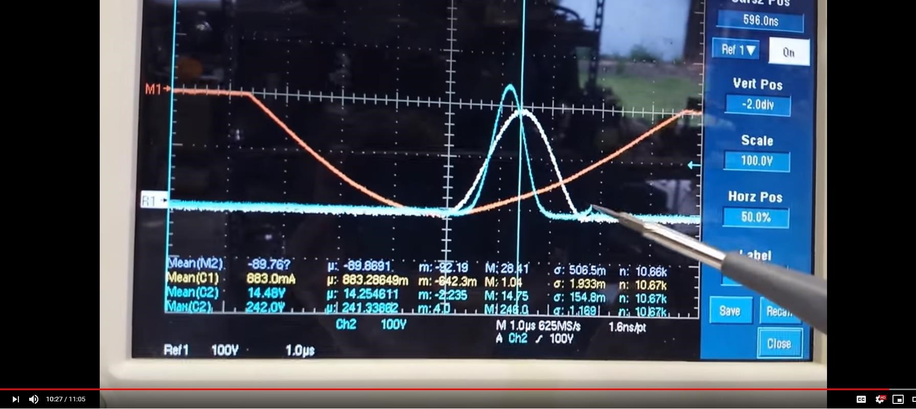
What does Graham show at minute:  4 : 54 on. 

Ref: @ 10 : 27

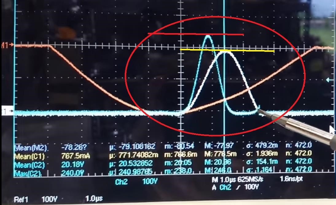
NOTICE: The Scope is 100 Volts per division.When Graham removed the Capacitors, the pulse was around: 200 Volts, when the Capacitors were removed, the Voltage was around 240 Volts. The sharper the Spike, the more E.M.F was Generated, thus the machine went Above Unity when more E.M.F was generated.

For this experiment, I added, a capacitor on each one of the Output Coils.

...

instead of a pulse width of about a micro second we have about 2 and a half microseconds.

Cop is about 1.3


Remember the difference:

The difference: 0.5 Watts Input 9.5 Watts Out vs 8.0 Watts Input 10.8 Watts Out


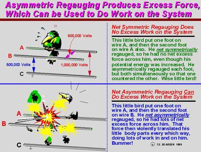
Now, remember, Ohms Law: I = V / R, Increase the Voltage, the Current is also increased for the same Resistance. The Potential Problem also pointed out by Tom Bearden:


Don't forget guys, methods exist to get the Voltage up! I started a thread, to get others looking at this: Voltage I hope we can all come together to work on the best methods to solve the Voltage Problem!

Best wishes,

   Chris

Ourbobby posted this 19 March 2020


Chris,

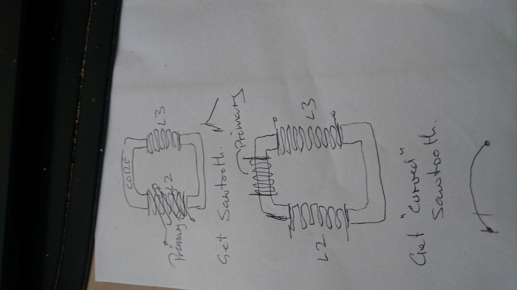
Here is a drawing that I hope explains the different outcomes, sawtooth and curved outcome, and L2 and L3  connection.

Regards

ourbobby


Chris posted this 19 March 2020

Thanks Ourbobby,

Not enough Coffee, I got you now, although the placement of the Coils should have little effect to the overall operation, only the Coupling and therefore the losses through un-coupled Flux.

When the secondary Coil is directly over top the Primary Coil, this is called Unity-Coupling. Transformers are both Unity Coupled and non-unity Coupled, they work the same either way.

Thank You for sharing, I appreciate your efforts as I do everyone here!

Best wishes,

   Chris

  • Liked by
  • cd_sharp
  • chocolate blanco
Ourbobby posted this 23 March 2020

Hi Chris,

               I think I have it. 10% is the charge time, which terminates as the alternate lenz kicks in and combined with the discharge gives us the sawtooth?

Regards

ourbobby


Chris posted this 23 March 2020

Hey Ourbobby,

My Friend, it sounds like you have it.

The Opposition of Force is Re-Directed, from the Secondary Coil to the Tertiary Coil. Essentially, the Primary pushes the Tertiary Coil, they work together, in unison, to push the Current, to Maximise the Electromagnetic Induction well beyond the current limit or Input = Output - Losses.

We target Electromagnetic Induction and the advancement of it.

Best wishes,

   Chris

Chris posted this 23 March 2020

My Friends,

I get impatient sometimes, I would really like to see more progress, I realise we all are so busy! The Virus, our Families, daily lives are so busy! Why are we all kept so busy?

Time is only a reflection of change. From change, our brains construct a sense of time as if it were flowing. As he puts it, all the "evidence we have for time is encoded in static configurations, which we see or experience subjectively, all of them fitting together to make time seem linear."

Ref: https://www.space.com/29859-the-illusion-of-time.html


So we are so busy because things change so fast, we are seeing so much change from minute to minute!

Our Partnered Output Coils must mirror our Daily Lives! We need Change, fast change, we need turns, but not too many!

I would like to share an analogy:


Ref: http://www.hyiq.org/Updates/Update?Name=Update%2018-07-11


IMPORTANT:

I had to tune this machine, find the best frequency, to observe effects. Each Coil has Capacity, Inductance and Resistance.

Each Coil is subject to Electromagnetic Induction!

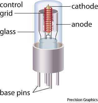
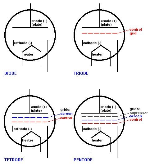
The Time Rate of Change of the Primary Magnetic Field "Generates" an E.M.F, then a Current can Flow. Each Coil sees the Other Coil as a Load! Each Coil attempts to Drive the other Coil! This situation becomes by definition, a Triode:

An electron tube used mostly for signal amplification, consisting of a cathode and anode (or plate) as in a diode, and an intervening wire mesh called the control grid. With little voltage on the grid, large currents can flow between the cathode and plate, but small variations in the voltage on the grid cause large variations in this current, allowing for large amplification of a signal applied to the control grid.

A type of vacuum tube that is used in audio and radio amplifiers and oscillator circuits. It is like a diode with the addition of a wire mesh control grid between the cathode and plate (anode) that controls current flow. A filament heats the cathode enabling it to release electrons. When a small voltage is applied to the grid, the current flow between the cathode and plate is changed accordingly. In some triodes, the filament is the cathode.

Ref: https://www.yourdictionary.com/triode


Each Coil squeezes off the Vacuum Flux, or the Magnetic Flux of its Neighbor! So, Current flows between the Cathode and the Plate! The Control Grid, controls the Flow, between the Cathode and Plate, simple a squeezing off of the Flow of Current.


In this analogy, if Magnetic Flux was to replace the Current, then simply, squeezing off the Magnetic Flux, if you like a Controlled Electromagnetic Induction Pump, then the Grid becomes the Action / Reaction Pair of the Partnered Output Coils, the Input Coil is the Supply of Current to the Grid. So Tom Bearden's analogy was right, if one looks at the VTA, Vacuum Triode Amplifier in the correct sense! Floyd Sweet allowed Tom Bearden to rename the VTA from the SQM The Space Quanta Modulator, or Space Flux Coupled Alternator. The term Alternator implying Electrical "Generator", by its very definition!

You see, Electromagnetic Induction is simple:

  1. Conductors!
  2. Magnetic Field Changing in Time!
  3. Right combination of Proximity and Turns. 

Electromagnetic Induction is Incomplete! There is more to learn! They stopped back in the 60's because they knew there was more here, more to learn, but it threatened their status quo! They shut it down and tole everyone, nothing more to learn here, its a finished now obsolete topic, when they knew it was not!


Remember: 

When the current in one half of the conductors in the coils (i.e., one of the bifilar elements in each coil) of the device is moving up, both the current and the magnetic field follow the right-hand rule.

The resultant motional E-field would be vertical to both and inwardly directed.

At the same time the current in the other half of the conductors in the coils is moving down and both the current and magnetic field follow the right-hand rule.

The resulting motional E-field is again vertical to both and inwardly directed.

Thus, the resultant field intensity is double the intensity attributable to either one of the set of coil conductors taken singularly.

Expressed mathematically:

E = ( B x V ) + ( -B x -V ) = 2 B x V


NOTE: The Coil Winding Direction as I have shown can play a role in the success you have.

Best wishes,

   Chris

Chris posted this 25 March 2020

My Friends,

I need to say to all readers; On regular occurrences I get PM's Emails or other correspondence saying:

I want to build a machine that gives about 500 Watts for free...


Now I have to say, all readers MUST start at the start! That way of thinking is unrealistic, at least when first starting! 

I strongly urge all members set small realistic goals, aim for 2 - 3 watts first!

Floyd Sweet his first unit was reported to be Six Watts! Although there is no documented evidence for this figure, there is a documented figure of: 19.1544 Watts on one of Floyd Sweets First Machines. You can read that here: Floyd Sweet Lab Notes.

Please, everyone, I urge you all, this is important! Be realistic, aim for a few Watts first, you can improve as you learn more!

But don't set your goals too high, where they become un-reachable! This will be Negative and you will quickly loose interest and not learn anything! We all have to start at the start! We have to! Its how Life works!

If you set small realistic Goals, then before you know it, you will have 500 Watts Output, but you must be realistic!

Best wishes,

   Chris

Chris posted this 26 March 2020

My Friends,

A Video to help understand What the requirements are for Energy:


I hope this helps others! A Milestone also!

I love Humanity and wish for so much more for all of Humanity and the World as a whole!

Best wishes,

   Chris

  • Liked by
  • Augenblick
  • Fighter
Chris posted this 26 March 2020

My Friends,

At this stage, for some of you, this is already well known, we have already touched on this before, but:

Now let us consider the losses. Copper or Cu I2R losses remain but may be minimized by using wire of larger than usual cross-sectional area.

Ref: Floyd Sweet - The Space-Flux Coupled Alternator


What are the I2R Losses? DC Resistance Losses! We already know this, but this is verification from Floyd Sweet, hidden in the middle of the texts.

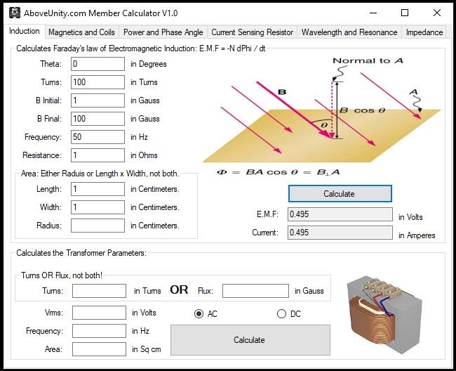
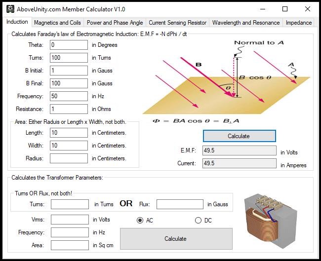
Using our Above Unity Member Calculator we can run a comparison:


By increasing the Cross Sectional Area by a factor of 10, we gain an output factor of: 49.5 / 0.495 = 100, thats a hundred times more for only 10 times Cross Sectional Area Increase!

Floyd Sweet was right! Again we have covered this before, but with a little more data this time.

Best wishes,

   Chris

Chris posted this 27 March 2020

My Friends,

A friendly reminder of an age old technology, we only need expand on a little:


Best wishes,

   Chris

Ourbobby posted this 29 March 2020

Hi,

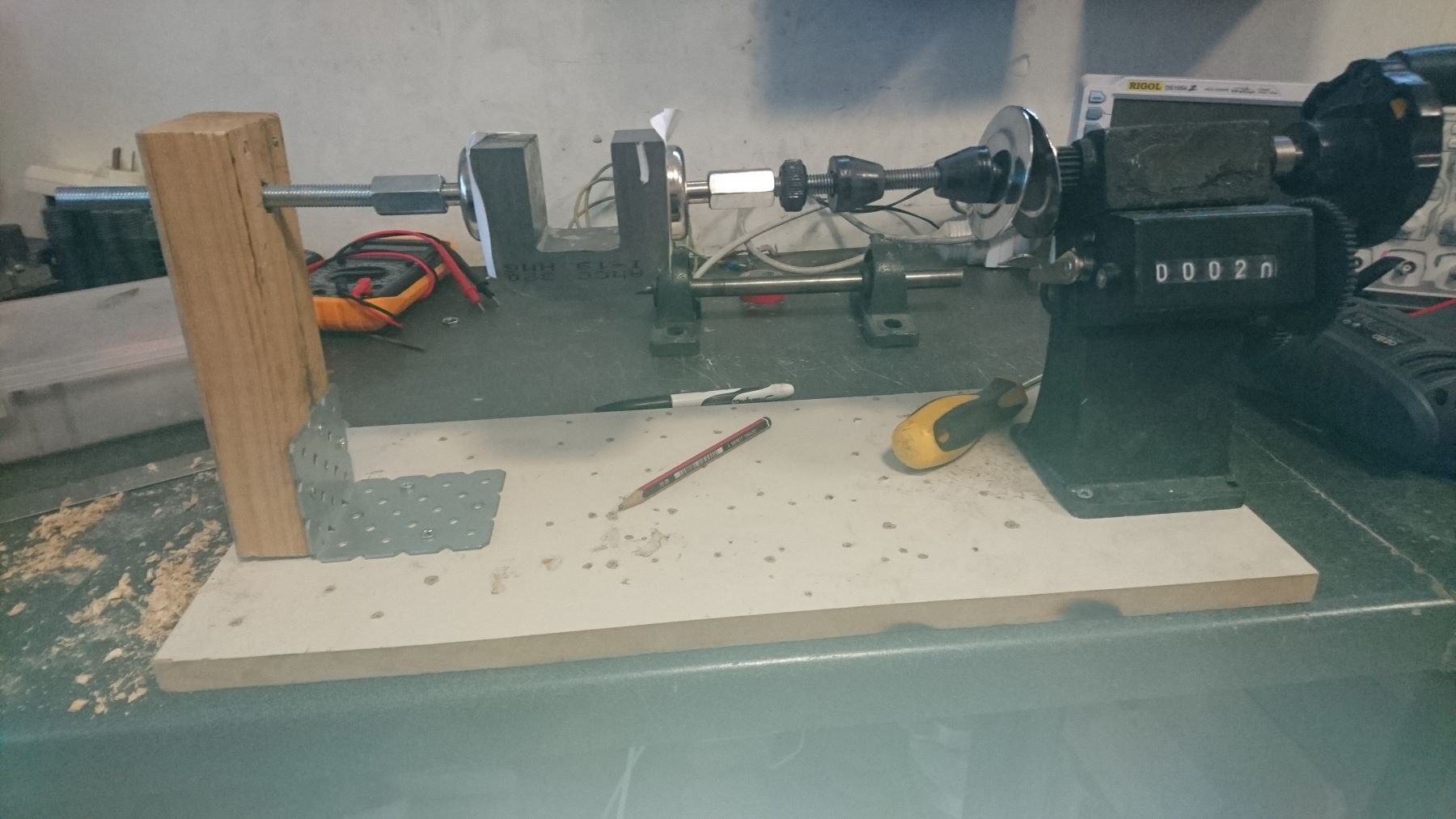
    Am looking at the Meg as an initial stage to understand the induction complement of the set-up of POC's. Looking at the JL Naudin build. So, I first have to rationalise the L2 windings over the middle of the C cores! For anyone looking at this. Here is my magnetic clamp solution, not perfect, but, OK for winding small number of cores. It uses two round neo magnets sold often with 6mm screw hooks.. My coupling iuses two long extention nuts 10mm to connect to winding machine and adjacent magnet.. I have drilled out two 10 mm bolts and tapped for 6mm threaded rod insert, then cut off the heads. It works!

Enjoy

ourbobby


Chris posted this 29 March 2020

Hey Ourbobby,

Very nice! If I may suggest, wind your POC Coils, x Turns of nice gauge wire, but wind one layer, say around 10 turns on the top of each coils also.

Then apply what we have learned. Find the Sawtooth Waveform, then you can go ahead and maximise the effects to get the best possible output.

Nice work, Thank You for sharing!

A Video for all:


Apologies, I said Excitation Coils, the Diagram labels the Coils I meant as Excitation Coils, earlier in the video as Power Coils. You may need this:


NOTE:

Checks still not in – 13 days late – Sparky explains that there is a little part in the Generator that he
has withheld from disclosure – A $1.50 part from Radio Shack that could be gotten at 30c in quantity
that is not a capacitor (no resonance effects) that divides the current somehow into the circuit being
Spherical 

With light bulb filament 

parallel, that puts a small µa current into the Power Coil as well as the Excitation Coil, that works with the Magnets in such a way that there is halved A Vector Complementarity (he calls this unit a ( “Vector Oscillator" )

Ref: Floyd Sparky Sweet Lab Notes.


Lets not forget, this is not the first time we have heard this, its not rocket science:


I hope this helps some!

Best wishes,

   Chris

  • Liked by
  • ISLab
  • Augenblick
Ourbobby posted this 30 March 2020

Hi Chris,

              Lets see if I have it! I wind two secondary coils and then on top of each secondary I wind a linked centre tap primary of ten turns. So what happens to the 100 turns primary on the MEG? What is nice wire?

regards

ourbobby


EdiT; I am stupid, I see it now!!!!!!!!!!!

  • Liked by
  • Chris
  • Augenblick
Chris posted this 30 March 2020

Hey Ourbobby,

Yes, but the 10 turn coil as a separate Coil, not electrically connected. No Center Tap, not yet, learn first then later you can try all that stuff.

Wind them as I have shown in my POC Image, you can have 4 Coils if you like? Its up to you, use one as a sensing Coil. So, Output Coils will be X Turns, Input, one Coil, 10 or so turns.

Don't forget, Delayed Conduction to get the Voltage Up. Current ( I ) = Voltage ( V ) / Resistance ( R ), as the Voltage increases, as does the Output Current.

Best wishes,

   Chris


  • Liked by
  • Augenblick
  • ISLab
Chris posted this 30 March 2020

My Friends,

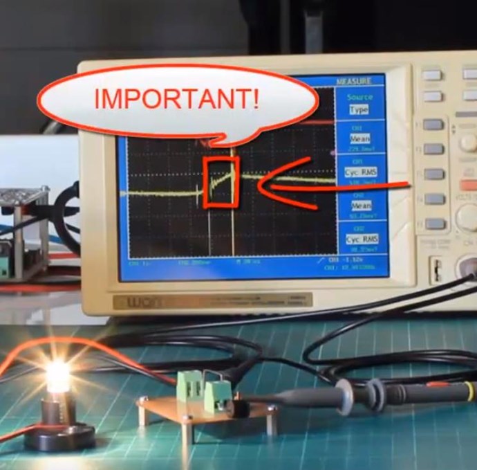
I have given everything, When I said you have to get the Voltage up, I gave it to you all, You see a large Voltage spike here:


Fighter has shown you the same, and done the same, given you all of his work:


There are different methods to get to the same end goal, many of us have shown this technology work.

My Friends, I fear many are here reading for their own selfish benefit! Some out there claim the invention for themselves! I read a post on another forum the other day, claiming the Invention, I said something, and they got all upset.

I fear the world is still not ready for this!

Although this means the majority miss-out, the minority is all it takes to spoil the whole thing. There is still too much Selfishness, Greed, and to be honest, some days I feel like shutting the whole lot down! The only reason I don't, is I know we have such a good bunch of people here, hard working, all sharing! It is those of you that keep this all going!

I posted this to the other forum today:

Well, looks like I am going to have to ignore your comments: "MY INVENTION"

In reality, Partnered Output Coils is the subject of this Thread and were around well before you came on the scene Seychelles.

@kolbacict - I worry for you! Your posts show many problems, are you OK?

Now, I am going to put this plainly, Go Replicate my series: Non-Inductive Coil Experiment - in Video Seven you will find information that will help you the most! All videos prior are important and a buildup to Video Seven.

Video Seven:


I get tired of trying to help everyone when others are either out for themselves or not willing to help themselves! I wont be doing this for ever! You have little time left! I suggest you do a lot more to help your Fellow Brothers and Sisters!

Your Greed, your Self Service, will be your DESTRUCTION!

You have a glorious Future if only you were to Evolve!

Best wishes,
   Chris Sykes


My Friends, this is all for you and because of you! Please support this effort, make this what it should be!

We have broken Ground, this should move like a Roller Coaster, growing and Growing, getting faster and faster, but I do still see problems! Be Safe and be Well My Friends!

Best wishes,

   Chris

Wistiti posted this 30 March 2020

Chris, my freind, dont lose your time and optimist by following this forum.

On my side i see great difference between the first forum you start and what we are now!


Thank you to be there, do not worry it,s more than apreciate!

Chris posted this 30 March 2020

Thank You Wistiti!

My Friend, you have been with me from the start! Your experiments are excellent! First Class! You have machines Charging both Batteries, Input and Output! I am extremely please you have seen what Humanity has to come! It is just the start! We have doors wide open once we have made those initial steps!

I very much appreciate your contributions!

Thank You My Friend!

Best wishes,

   Chris

Jagau posted this 30 March 2020

I join Wistiti for the same words, I think that says it all,
in these difficult times for all i believe the best is yet to come.
You even see google can change you got the proof this week.
A big thank you for what you bring to this forum, as a founder and for having the patience to support us.

It will be fine
Jagau

Chris posted this 30 March 2020

Thank You Jagau!

I agree, the best is yet to come! We have come a long way, already, but yes, the Future will be Glorious! We only need work hard for it!

So many Good People here! I thank You All! Humanity is on difficult times and we are getting through it much better than what we have in time past!

Best wishes My Friend!

   Chris

Chris posted this 01 April 2020

My Friends,

I am sorry, this may be a little off topic, but I have re-watched the old Star Trek Movies and Series.

I guess you could say I have tried to base my work on the way Mr Spock has shared his effort, trying to be Logical as possible! I would like to share some quotes, in remembrance of the great man and the roll he played:

Logic is the beginning of wisdom, not the end.


The miracle is this: the more we share the more we have.


In reference to Leonard Nimoy. Also another of my favorite, James Doohan, truly, all of them are legendary! All the way up to our current Movies...

Best wishes,

   Chris

thaelin posted this 01 April 2020

Aye and Scottie knew it well. One of his sayings stays with me forever. "Fool me once, shame on you. Fool me twice, shame on me." Hope that is taken in the correct context. Don't fall for it twice, just move on.

Chris posted this 01 April 2020

Hey Thaelin,

Yes I remember that one also!

If you have spare time due to the Virus, watch "For the love of Spock" - Its good!

Best wishes,

   Chris

We're Light Years Ahead!
Members Online:

No one online at the moment


What is a Scalar:

In physics, scalars are physical quantities that are unaffected by changes to a vector space basis. Scalars are often accompanied by units of measurement, as in "10 cm". Examples of scalar quantities are mass, distance, charge, volume, time, speed, and the magnitude of physical vectors in general.

You need to forget the Non-Sense that some spout with out knowing the actual Definition of the word Scalar! Some people talk absolute Bull Sh*t!

The pressure P in the formula P = pgh, pgh is a scalar that tells you the amount of this squashing force per unit area in a fluid.

A Scalar, having both direction and magnitude, can be anything! The Magnetic Field, a Charge moving, yet some Numb Nuts think it means Magic Science!

Message from God:

Hello my children. This is Yahweh, the one true Lord. You have found creation's secret. Now share it peacefully with the world.

Ref: Message from God written inside the Human Genome

God be in my head, and in my thinking.

God be in my eyes, and in my looking.

God be in my mouth, and in my speaking.

Oh, God be in my heart, and in my understanding.

Your Support:

More than anything else, your contributions to this forum are most important! We are trying to actively get all visitors involved, but we do only have a few main contributors, which are very much appreciated! If you would like to see more pages with more detailed experiments and answers, perhaps a contribution of another type maybe possible:

PayPal De-Platformed me!

They REFUSE to tell me why!

We now use Wise!

Donate
Use E-Mail: Chris at aboveunity.com

The content I am sharing is not only unique, but is changing the world as we know it! Please Support Us!

Thank You So Much!

Weeks High Earners:
The great Nikola Tesla:

Ere many generations pass, our machinery will be driven by a power obtainable at any point of the universe. This idea is not novel. Men have been led to it long ago by instinct or reason. It has been expressed in many ways, and in many places, in the history of old and new. We find it in the delightful myth of Antheus, who drives power from the earth; we find it among the subtle speculations of one of your splendid mathematicians, and in many hints and statements of thinkers of the present time. Throughout space there is energy. Is this energy static or kinetic? If static, our hopes are in vain; if kinetic - and this we know it is for certain - then it is a mere question of time when men will succeed in attaching their machinery to the very wheelwork of nature.

Experiments With Alternate Currents Of High Potential And High Frequency (February 1892).

Close