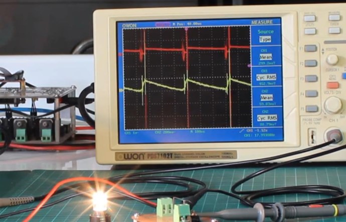
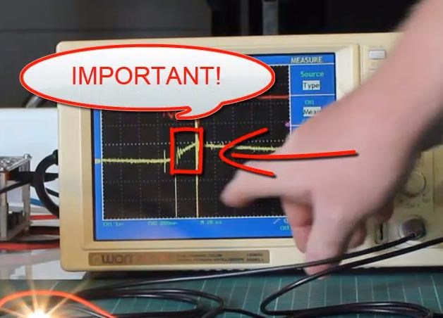
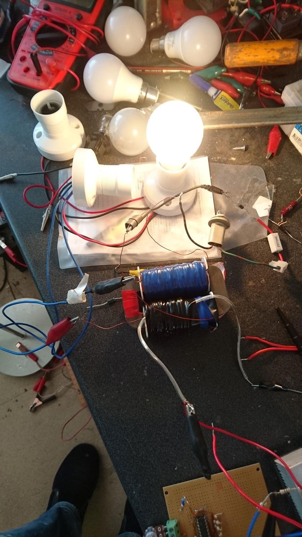
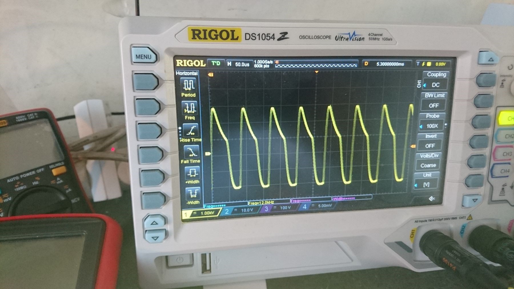
Chris's Non-Inductive Coil Experiment

  • Topic Is Sticky
  • 29K Views
  • Last Post 04 July 2023
Chris posted this 08 October 2019

My Friends,

I am going to show a small experiment, one that follows the works of Andrey Melnichenko and even Tariel Kapanadze's works and as we know many others.
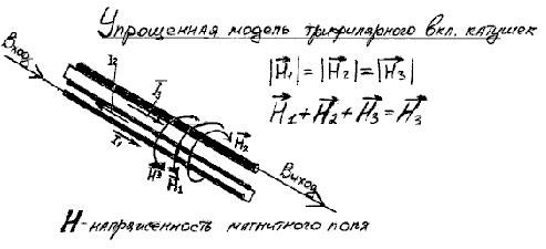


We have discussed here before, the fact that H3 is H3 simply because H1 and H2 cancel out: H1 + H2 + H3 = H3, why is this so, because H1 is Positive and H2 is Negative! We have seen this equation before: 1 + -1 + 1 = 1.

I think with Fighter's success recently, its time for some hands on!

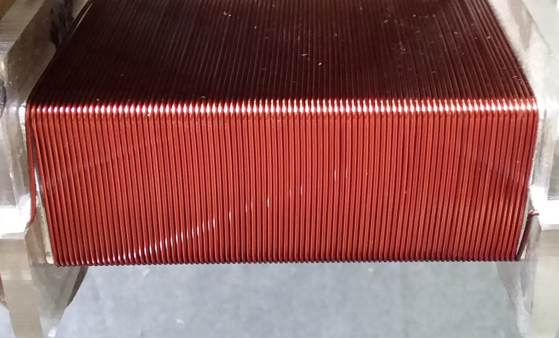
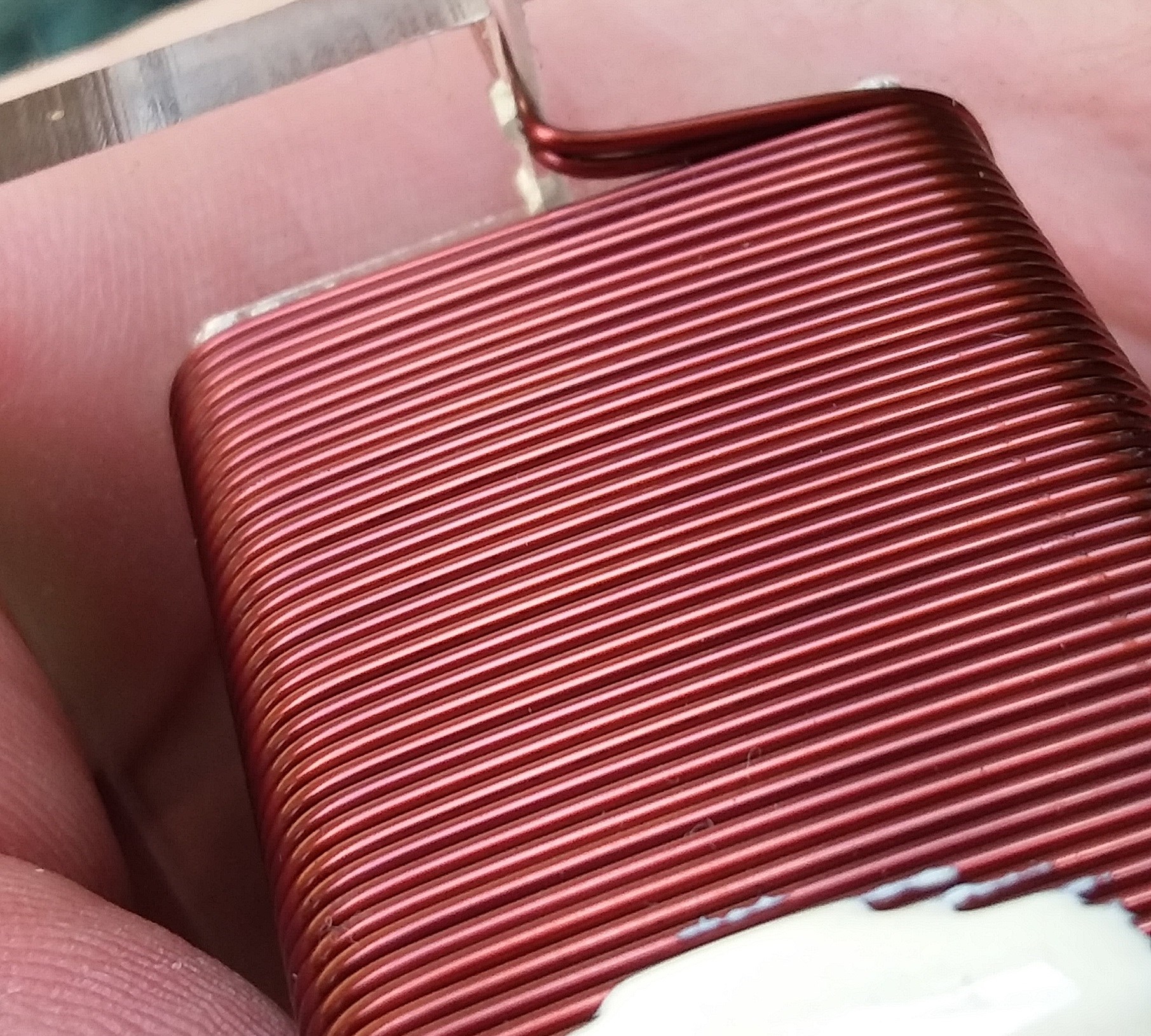
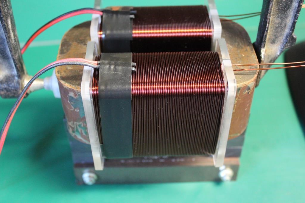
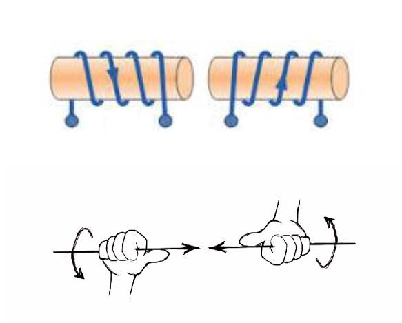
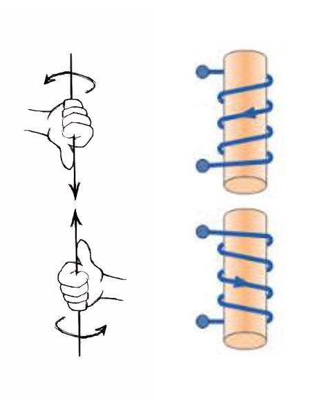
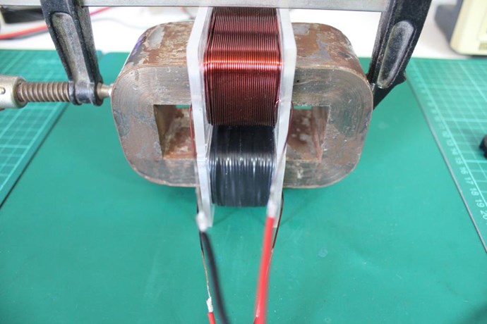
  • First Layer: 88 Turns.
  • Second Layer: 43 Turns.


Layer One:


Layer Two:
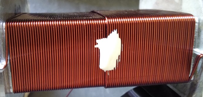
 

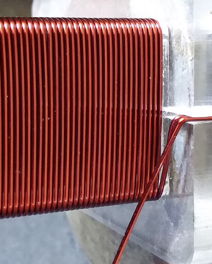
Turns Direction:
 

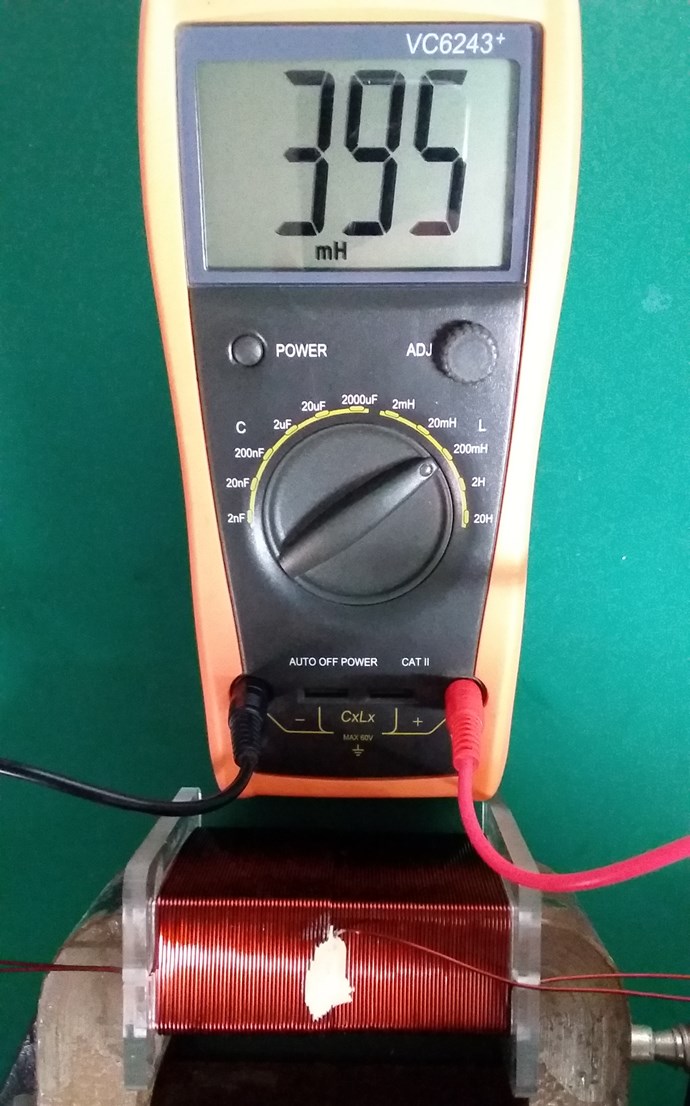
Layer One Inductance:
 

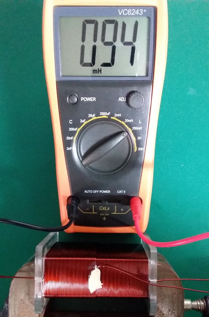
Layer Two Inductance:
 

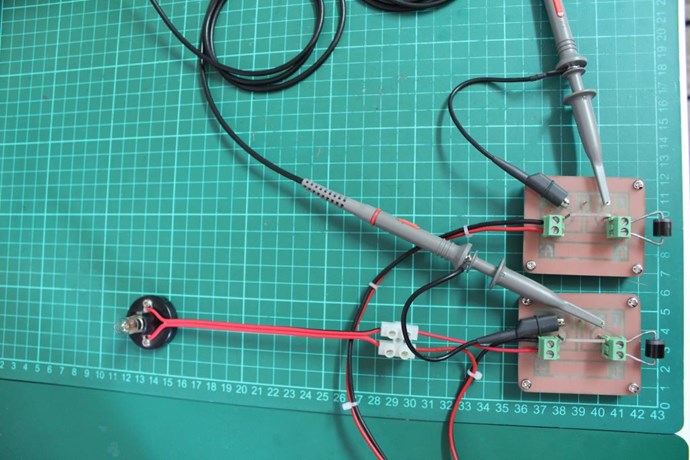
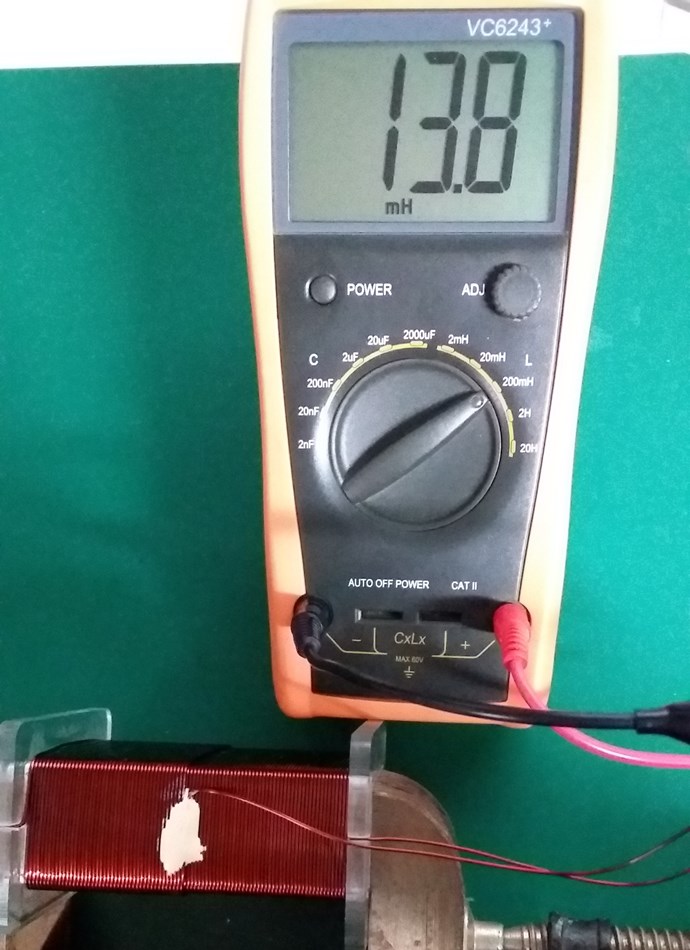
Non-Inductive Connected:
 

Layer One Resistance:
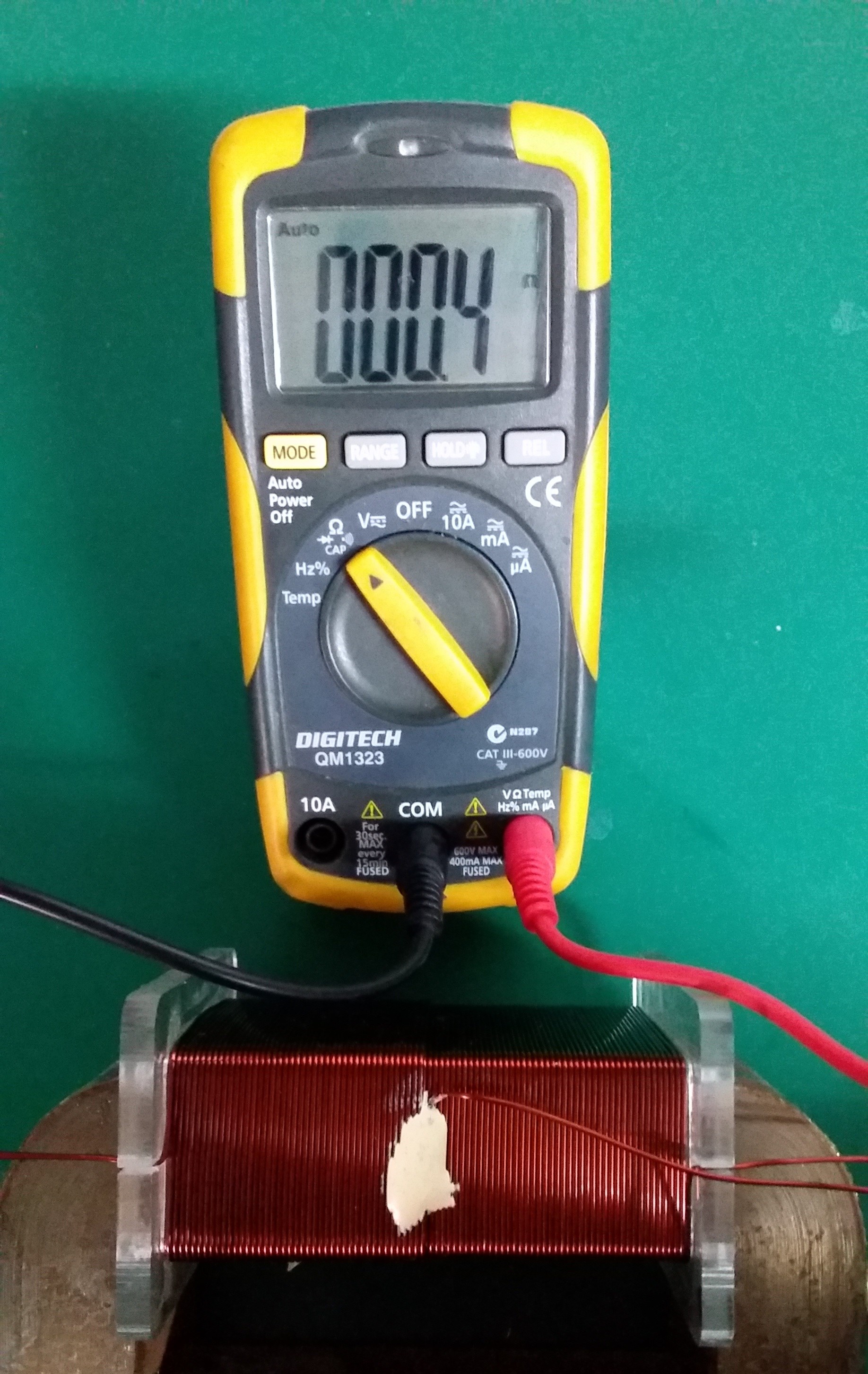
 

Layer Two Resistance:
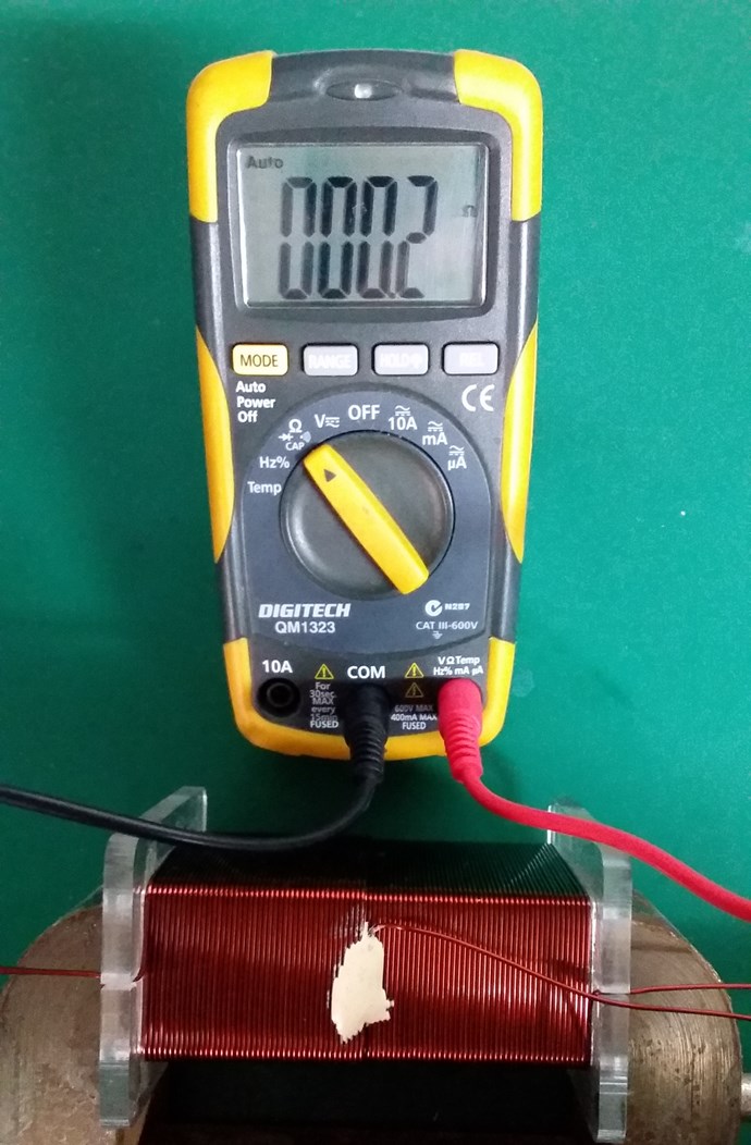
 

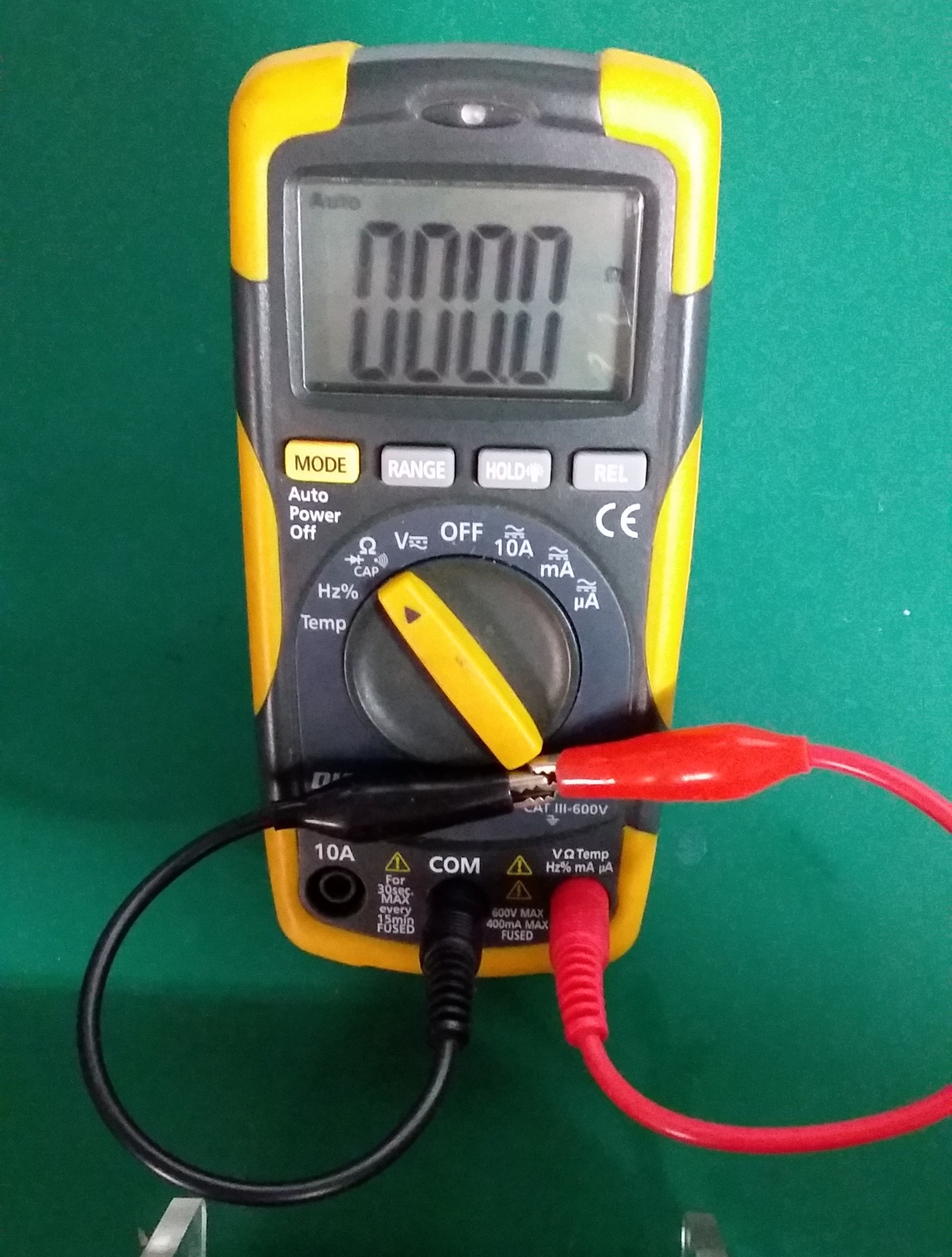
Closed Loop Resistance:
 

My Coil, like Andrey Melnichenko's, is 0.33 + -0.33 + 0.33 = 0.33.

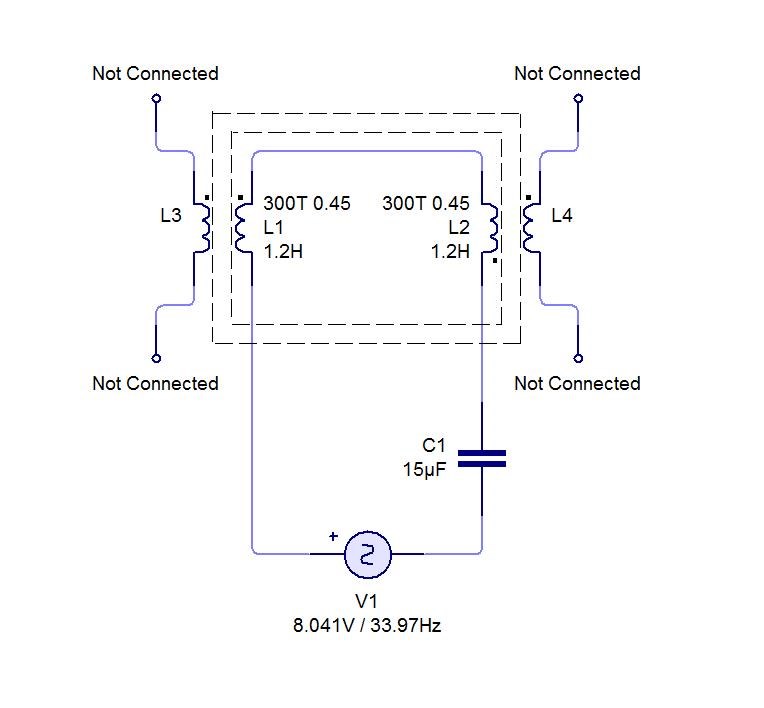
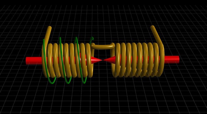
Two thirds of my Coil is canceled out. My Circuit looking like this:
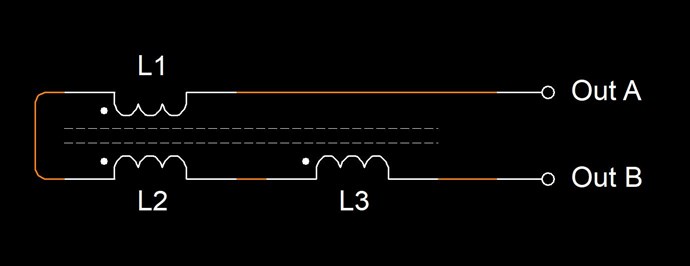
Where:

  • L1 and L2 are Non Inductive.
  • L3 is Inductive.


If this Coil is carrying 1 Ampere of Current, and exactly one half of the Coil is Non-Inductive, then Turn for Turn, only 45 Turns will create an M.M.F, which is considered as 45 Turns x 1 Ampere = 45 Ampere Turns or 45At.

Science tells us, that Turn for Turn, where we have Non-Inductive part of the Coil, this part of the Coil does nothing! Creates no Magnetic Field, therefore does nothing.

However, from Experiment, we know that this part of the Coil DOES do something! Remember Floyd Sweets paper: Nothing is Something, this is the same!

At Resonance, we have a perfect Standing Wave! We know this as Magnetic Resonance! Where each Magnetic Field is 180 Degrees out of phase:
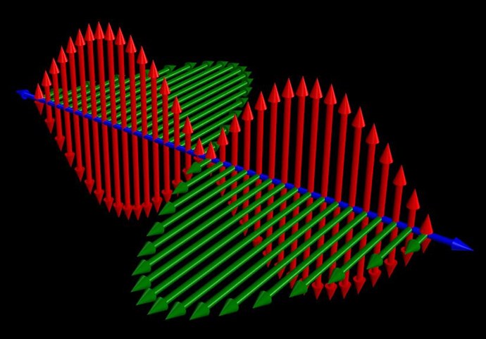
 

Now, straight away, we should see a problem! Why? Kirchhoff's Current Law says the Current must be equal at every node, but we have Turn for Turn, one Coil that is Inductively Zero, and another Coil that has only a part of the Induction canceled!

In the specific case of positive charges moving to the right and negative charges to the left, the effect of both actions is positive charge moving to the right. Current to the right is:

I = da+ / dt + da- / dt

Negative electrons flowing to the left contribute to the current flowing to the right.


Each node does not equal the other, so the Circuit must balance out, Current is Increased as the Standing wave shows us.

Remember what Induction is? See here: Non-Linear Inductance

Induction gives us an approximation on the Coils ability to carry a Current: L = ε / di / dt

By Bringing a Coil arrangement like this into Resonance is our task.

Where each Electromagnetic Wave travels in opposite directions. One through the other in the same space.

THE NATURE OF SPACE

Space itself is the ability to accommodate energy. Consider for a moment the following illustration:

A signal (energy) is transmitted from point A to point B. A and B are separated by a finite distance. Consider three periods of time:

  • The signal is launched from A.
  • 2) The signal resides in the space between A and B.
  • 3) The signal arrives at B.

If (3) occurs simultaneously with (1) we say that the signal has traveled at infinite velocity. The signal has never resided in the intervening space and therefore there exists no space between A and B. A is virtually at the same point in space as B. For real space to exist between A and B it is necessary that a signal travelling between them be "lost" with reference to both points for a finite period of time.

Now we know that for real space to exist between two points a signal travelling between them will propagate at a finite velocity c, ( c = 1 / √με )

If a signal will not travel between two points, as in the case when c = 0, then we can also conclude that there is no link or intervening space between them. 

Ref: Floyd Sweet - Nothing is Something.


Floyd Sweet tried very hard to make c = 0! What does this mean? It is simply a Standing Wave, a Team Wave was used:

It is a simple matter using the equations E / H = √με and c = 1 / √με for a team wave to get rid of H and c and so convert the first equation into the well known equation for energy density in the so-called electrostatic field.

Ref: Floyd Sweet - Nothing is Something.


I have pointed out: Why 'C' is equal to One in these Devices.

We have a lot of data!

   Chris

Order By: Standard | Newest | Votes
Chris posted this 01 April 2020

My Friends,

I would like to make some more examples obvious.

We have a reasonable good historical record! I have shares all my research here: Reference and here on my two websites, hyiq.org and aboveunity.com. I have done many thousands of experiments over the years, most not any real value, some very valuable! I always learnt lots by experimenting!

Recently, in other threads, we have covered again some more on the thread: Non-Linear Inductance

Inductance ( L ) is the Rate at which Amperes can flow through the Coil in Time, this is defined as:

L = di / dt

One Henry is where One Ampere transitions the Coil in One Second. With Back E.M.F: 

L = ε / di / dt

Where ε is the Back E.M.F, restricting the Current Flow, created by the change in Current  that produced the E.M.F.


We know, Faraday's Law of Electromagnetic Induction, as a Magnetic Field Changes in the Proximity of a Conductor, this creates a Voltage! Well the same if true of the Inductance, the Inductance changes with the Magnetic Field!

This means, you could say as the Inductance changes, a Voltage will also be Created / Changed. Thus, simply, because the Magnetic Field is Changing.

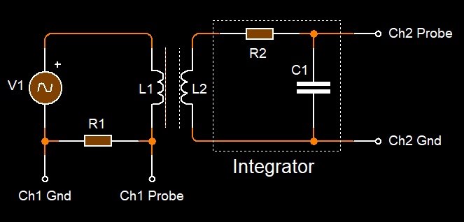
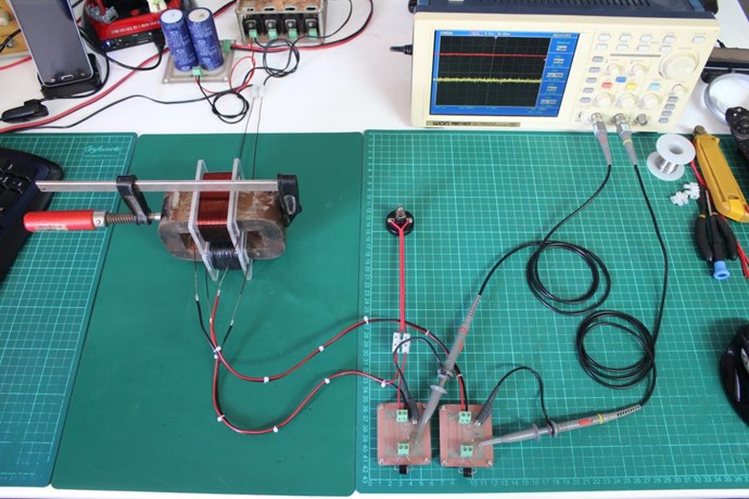
Remembering Inductance is the ability for a Coil to pass Current. The BH Curve being a function of the Current to the Voltage, the Primary Current to the Output Voltage. Sites out there help you measure the BH Curve, sometimes known as the Hysteresis Curve, using a similar Circuit:

Note: You need to plot X and Y on your scope!

Most here will know, an Air Core does not Saturate, having no BH Curve, there is still an Inductance however!

What does it take to Saturate a Core? Well there are Core Values, specified on the Manufacturer Datasheet, under Bh or AL or something similar that tell you what the Core is rated to.

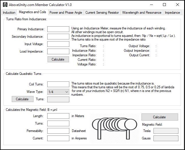
Magnetic Field if as we have learnt, the Turns carrying Current vs the length of the Inductor. Our AboveUnity.com Member Calculator has a small calculator in there to help you with this:


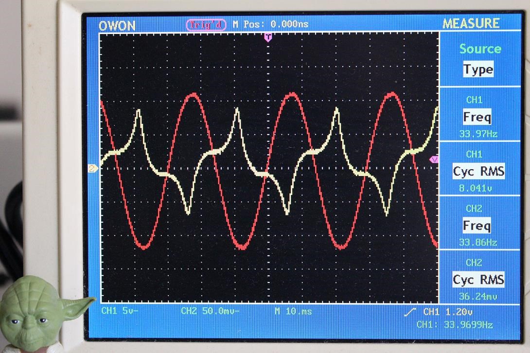
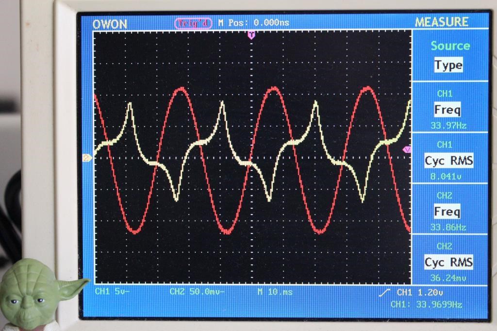
This will help you see what the Magnetic Field is at Core Saturation. How can one find Saturation, the sharp peaks on Current Waveform is one indication:

Ref: Partnered Output Coils - Free Energy


We must remember, at Saturation, we can have very bad Burnouts:


So please be careful! 

What occurs, the Inductance is lost, the Inductor becomes a straight DC Resistance, loosing all its AC Resistance, or Reactance, and the Input Current goes very High! The Transformer can Burnout as a result.

Best wishes,

   Chris

  • Liked by
  • Augenblick
  • ISLab
Chris posted this 02 April 2020

My Friends,

I cant recommend this more! A very good documentary!


0.56 + 0.82 + -0.59 + 0.56 = 1.35

I don't get why the negative is ignored?

Electricity and Light, how they are related.

Best wishes,

   Chris

  • Liked by
  • Augenblick
Chris posted this 02 April 2020

My Friends,

In regards to the above post, not the last one, but one before that, I would like to add, if anyone has gone and read the link investigated the image, read the posts, and remembered what was said, this perhaps this line may have stuck out at you:

You can see, an external Magnetic Field added to a System, and Moving this Magnetic Field, in the System, can, and does, add energy to the System. Thus the "Generation" of electrical Energy.

Ref: Partnered Output Coils - Free Energy


What was I showing? Well lets look again: Partnered Output Coils - Free Energy


Any and all Permanent Magnets work, to imply otherwise is just foolish. Magnetic Fulx when moving, no matter from what ever source, Invokes Electromagnetic Induction:

Quote from: Floyd Sweet

Rather, what happens is that the individual packets of quanta are polarized by the initiating and sustaining coherent force the field of the primary magnets or in special cases, electromagnets.

Floyd "Sparky" Sweet - The Space-Quanta Modulated Mark 1 Static Alternator 


Maybe its time to repost this image:


Please ask the question, what are the Magnets actually doing in the Core, it is not just the Movement which I have stated! It does other things also!


I am a Student in the School of Life, always will be, my entire life, never an Expert!!!

Partnered Output Coils - Free Energy


We have many very smart members here on this forum, some helping me understand more every day! I have said, it requires a bit of work, fiddling is required to make this work! But one day soon, maybe this wont be quite as tough of a learning curve? I cant predict the future, not yet anyway, but I know the now.

I want to thank: Zanzal, YoElMiCrO, Vidura and Jagau for their recent contributions. I hope we can share more soon.

Best wishes,

   Chris

Chris posted this 03 April 2020

My Friends,

The following Documentary is very good! Many good relevant points in this Documentary, think Nothing is Something by Floyd Spark Sweet:


What is nothing? It is Everything!

Best wishes,

   Chris

Chris posted this 03 April 2020

My Friends,

I don't want to hijack others threads, and without creating a new thread, this is the next best thread.

Recent work focuses some, on Permeability. Now documentation for Permeability is poor at best. The definition of Permeability is:

1: the quality or state of being permeable

2: the property of a magnetizable substance that determines the degree in which it modifies the magnetic flux in the region occupied by it in a magnetic field

Ref: Merriam-Webster - Permeability


I would like to speculate some.


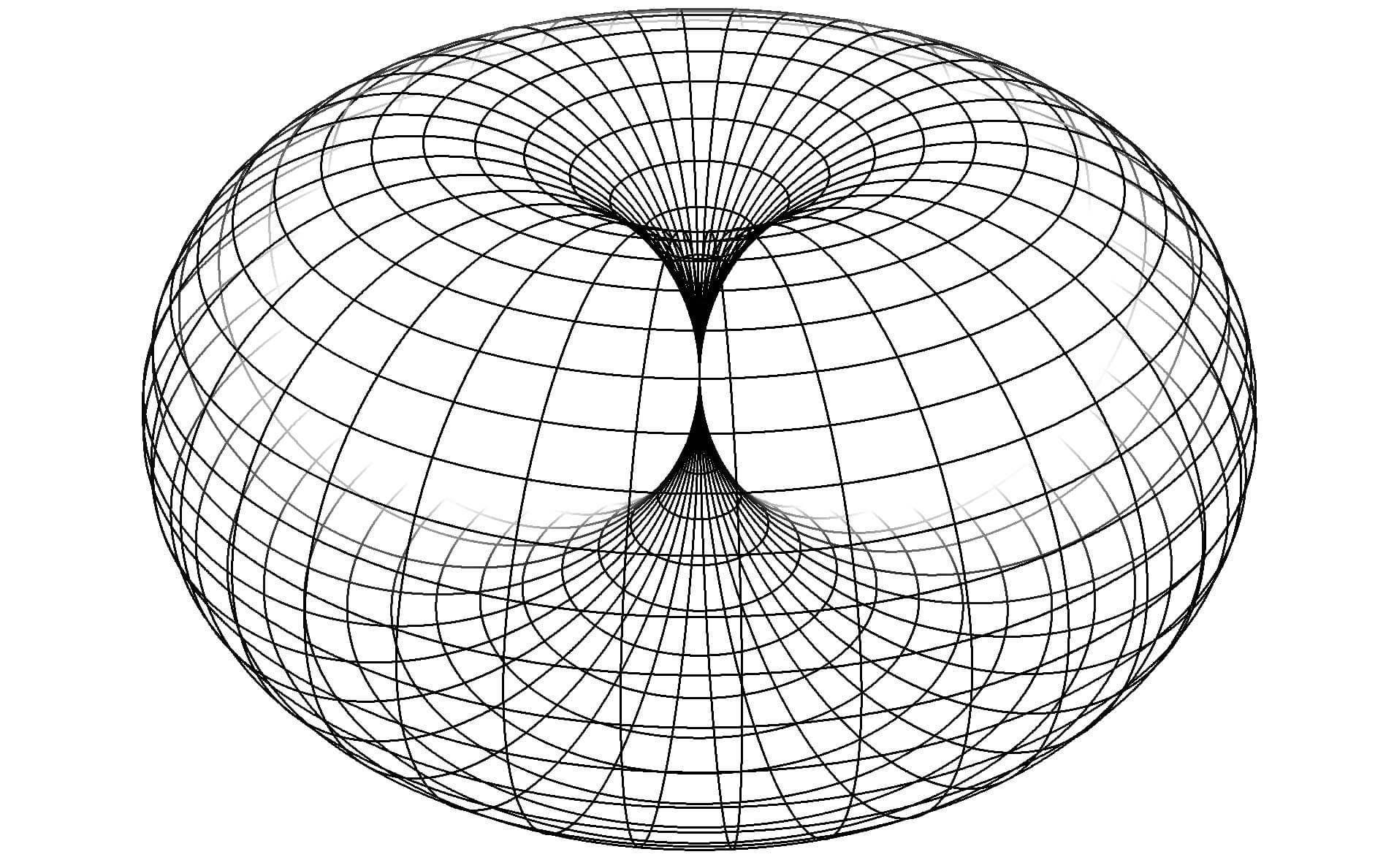
I am thinking in terms of Coil and a Core having Mass and distorting Space Time, thus the Toroid.

I want to Visualise Permeability in a 3D Space, a localised Space Time Distortion. I believe the best way to Visualise Saturation and Permeability as a Toroid:


Note: This is a localised area of distorted Space Time due to the Mass.

Inside the Toroid, we have a region of Space, if you like Space Time, that can change, it has a Curve to it.


Here you can see the Curve I am getting to, please excuse my terrible art:


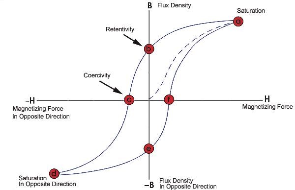
The BH Curve, or Hysteresis Curve are related to the Permeability:


Ref: Datasheet on Magnetic Cores.


We know, as the Magnetic Field Density ( B ) increases, the Plot starts to Curve, in Red. When the line flattens out, this is Saturation, no more Magnetic Field can fit inside the Core! The Core Material is Saturated! Thus the BH Curve:


We know Space Time can be Flat and also can be Curved. Mass distorts Space Time!

Mass is not a property of space (or space-time itself), but of physical objects in classical physics. In General relativity, it is difficult to speak about mass clearly, there is no good general definitions. Now, there are two naive metaphysics about space-time. The substantivalists think that space-time exists by itself, even if its not "made" out of something, and that if you remove all matter from it it is still here (but empty). The relationalists on the other hands, think that space-time is emerging from the relations between matter and that it does not make sense to speak of space-time itself without matter. For substantivalists, space-time has points that "really" do exists, while for relationalists it does not.

Ref: physics.stackexchange.com - Does spacetime have a "mass" value? or What is "Spacetime ...


The E = mc2 equation which we know to be Energy ( E ), Mass ( m ) and the Speed of Light2 ( c2 ) is a form of Energy ( Mass–energy equivalence ). Energy distorts Space Time:

Since matter carries energy (via Einstein's famous relation that energy is mass times the speed of light squared), such objects will have a gravitational field and so they will distort space-time. So one way in which a charge or a magnet will distort space-time is by virtue of its matter.

Ref: Do electric charges and magnets distort space, in the way that a source of gravity does?


If I understand this correctly, then Permeability must be related to Energy, or at least to the Flow of Energy! This is the Green Curve above.

Space Time is Permeable, known as Vacuum Permeability: μ₀ = 1.25663706 × 10⁻⁶ m kg s-2 A-2

The physical constant μ₀, commonly called the vacuum permeability, permeability of free space, permeability of vacuum, or magnetic constant, is the magnetic permeability in a classical vacuum.


Engineering the Vacuum:


After a brief review of the foundations of (pre-metric) electromagnetism, we explore some physical consequences of electrodynamics in curved spacetime. In general, new electromagnetic couplings and related phenomena are induced by the spacetime curvature. The applications of astrophysical interest considered here correspond essentially to the following geometries: the Schwarzschild spacetime and the spacetime around a rotating spherical mass in the weak field and slow rotation regime. In the latter, we use the Parameterised Post-Newtonian (PPN) formalism. We also explore the hypothesis that the electric and magnetic properties of vacuum reflect the spacetime isometries. Therefore, the permittivity and permeability tensors should not be considered homogeneous and isotropic a priori. For spherical geometries we consider the effect of relaxing the homogeneity assumption in the constitutive relations between the fields and excitations. This affects the generalized Gauss and Maxwell-Ampère laws where the electric permittivity and magnetic permeability in vacuum depend on the radial coordinate in accordance with the local isometries of space. For the axially symmetric geometries we relax both the assumptions of homogeneity and isotropy. We explore simple solutions and discuss the physical implications related to different phenomena such as: the decay of electromagnetic fields in the presence of gravity, magnetic terms in Gauss law due to the gravitomagnetism of the spacetime around rotating objects, a frame-dragging effect on electric fields and the possibility of a spatial (radial) variability of the velocity of light in vacuum around spherical astrophysical objects for strong gravitational fields.

Ref: Electrodynamics and spacetime geometry: Astrophysical applications


Again, I want to mention: Zanzal, YoElMiCrO, Vidura and Jagau, as much of this thinking has been spurred on by them! I have not thought about Coils quite like this before.


Good video, but this guy is super skeptical! The video in the last post, from Professor Jim Al-Khalili, disputes some data in the PBS Videos, Dr Matt O'Dowd. Please beware of this!

Please remember I am still learning this stuff! 

Best wishes,

   Chris

  • Liked by
  • YoElMiCrO
  • Augenblick
dale morgan posted this 05 April 2020

Hello,

There are problems with the terminology that Classical scientists use. Dark Energy and Dark Matter are actually called Dark because they cannot be observed. You can't measure them directly. Bearden covers this in several of his papers. He states that Dark Energy is actually the Virtual Particles that we are immersed in, from the nucleus on out into space on the other side of the universe. Can't see it or measure it so it's called Dark as a way to talk about it as a specific entity. I've been re-reading all of his papers to bring it back to the top of the brain so at this moment I can't say specifically which paper has what. Bearden repeats the same thing in many of his papers to get the info out there to those that are interested.

What he says about the function of magnets, how they work, is pretty straight forward. So is Howard Johnson's description. The field lines that can be shown with Magna View are an ordered Steady State flow of Virtual Particles as in Van Flandern's waterfall. NESS, non equilibrium steady state flow.  The formation of a magnet creates an ordering of the atoms within the material. Several billions of little dipoles, (magnets), aligned and fixed in mostly the same direction. Kind of like a magnifying glass. Concentrated in a small space.  I think of it as a Vacuum Tap, like tapping a keg of beer. Can't get the beer out without it, (a coil is basically the same thing).

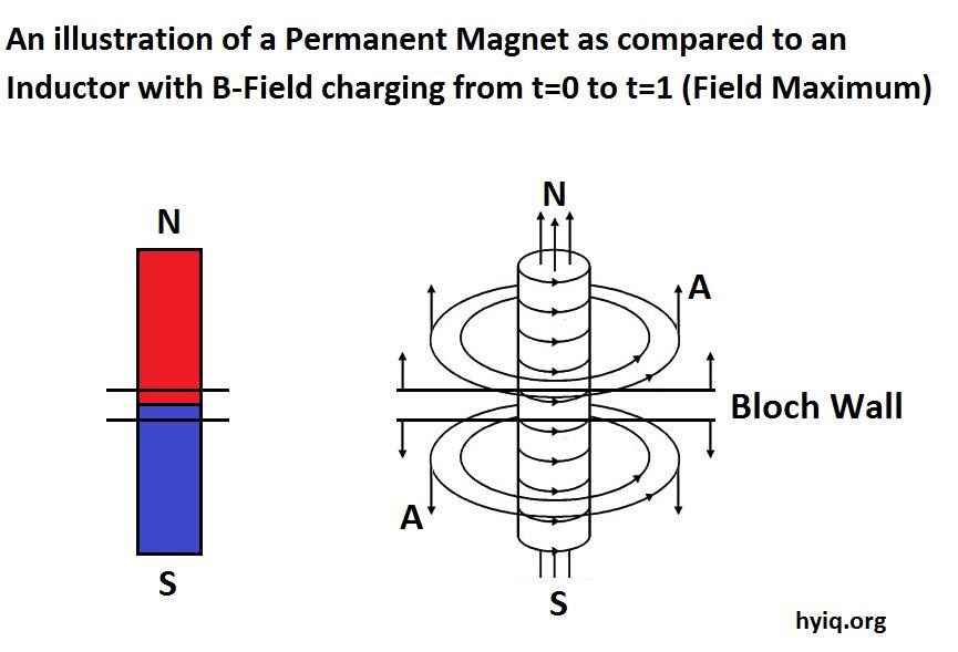
But we don't see the keg... Virtual Particles are not single particles as they are most commonly thought of. They are EPO's. Electron/Positron Pairs which do not have enough energy to pop into our 3-Space on their own. They need to hit some mass. So the visible magnetic field we can 'see' has to come from someplace... can't create or destroy energy. The Bloch Wall is a boundary layer between domains of orientation within the magnet. This is a sort of filter which separates the EPO's into discrete units. Positive and negative moving in opposite directions. Normally most of this happens near the center of the magnet between the poles. It is an inflow of energy into the magnet that we cannot see or measure. This action is the power behind the magnets field. The strength of a magnet is determined by the strength of the applied magnetic field that created the magnet in the first place. As is normal a large coil is used to make magnets, however the field in the magnet is only paid for once during it's creation. The field from a coil has to be paid for continously. Generally the same effects can be gotten from either. It's a matter of economics or complexity. I like to use both. Something From Nothing is a very good title as the magnetic field has to come from somewhere. No magic here.


In my own opinion, Spacetime Distortion is being misrepresented by that terrible graphic which looks like a funnel. That shape may represent a path that an object might follow upon being captured by the gravitational field. I believe that a more accurate representation would be like the layers of an onion. If anyone is familiar with Optics then the refraction of a beam of light through the surface of a layer of glass is a good way to see it. A fishing pond is a good way to visualize it also. The fish is not actually where it looks like it is. So relating it to an onion we have multiple layers, multiple surfaces of refraction. As the strength of the gravitational field increases, getting closer to the surface of the mass, the number of layers increases, the path becomes steeper. Thus at any point of 'capture' in any direction the path will 'follow' the shape of the funnel, generally.


I have spoken loosely here to try to paint a picture that isn't highly technical in nature. The point is that the terminology can be misleading in some cases. It can screw with your perspective enough to have you going in circles, not gaining a clear understanding. Certainly in some of the videos clear understanding is not what they want to teach. The electron is called negative because Ben Franklin flipped a coin, an arbitrary choice. In some cases it's easier to think of it as being positive.... 

Hopefully I haven't sounded like an arrogant ass here. I do not want to offend anyone and I certainly do not know everything! However I will have nothing to do with the Box or the limits that Classical Science try's to impose upon us.

Have a great day,

Dale


Chris posted this 05 April 2020

Hey Dale,

Nice Post, thanks!

I agree, dont be bound by someone elses box!

I read this, its also helpful:

Ref: Modern Nonlinear Optics, Part 2 - edited by Myron W. Evans


Although, this theory and background is useful, we must realise, as Vidura has said, we are currently working in areas that may not have anything to do with this field. I am interested in attempting to know more so I can understand more.

An analogy:

A New Tesla forms right in front of you, its beautiful, drives like a dream and you are very grateful! But you cant stop wondering how and why it formed right in front of you and this bugs you. You need to investigate more and more! It becomes an obcession and you hardly drive that beautiful Tesla because your'e busy attempting to find the reason for its appearance!

Best wishes,

   Chris

  • Liked by
  • Augenblick
Chris posted this 05 April 2020

My Friends,

I tried to join Twitter today - It wont let me! Keeps sending me around in endless circles... I guess the @elonmusk bit was not really an acceptable thing in their opinion!


Note: This is on Account signup, not even doing any posting at all, before I posted anything.

I see this sort of thing a lot more now that ever before!

Best wishes,

   Chris

  • Liked by
  • AETHERIC_MIND
  • Augenblick
thaelin posted this 06 April 2020

You do not need that forum Chris. They would never allow you to post the truths on what we are about anyhow. If you post anything that is contrary to the system of things, it will be edited out or your account seized or the likes. We come here to seek the truths on things being investigated. To thine  own self be true. And then share the truth with others as you have already been doing.


Many things will come to light soon.

Chris posted this 06 April 2020

Thanks Thaelin!

I was going to send Elon Musk a message, he is perhaps one of the few wealthy that may listen to reason. As you say, the message will likely be destroyed before he receives anyway.

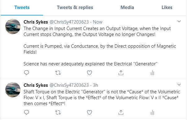
Conventional Science does not understand the Electrical "Generator"!

Shaft Torque is not the Cause of the Volumetric Flow we know of as Watt Seconds ( V x I ). Shaft Torque is the Effect, only occurring after the Volumetric Flow is achieved.

Simple Experiments give us a lot of real data, if we take the time to study what we are shown. Voltage is Free, Science agrees on this point! Current is not Free, at least according to Science. However, NI, the Ampere Turns, is equivalent to the M.M.F, and the Magnetomotive Force is a fundamental Force that must be dealt with!

CD's recent experiments show a working Machine, a DUT that is obviously Above-Unity, showing all the effects we need to observe. Current is sent back to the Power Supply, the Input, or Consumption Current, is Reduced, when in operation, which is required, the machine powers a Load for less energy that the machine required just to operate. The Load reducing the Input power, not increasing it like we have been brain washed into expecting!

We really cant make the machines any more simple, its Three Coils, One Input Coil, Two Output Coils, Partnered Output Coils, configured correctly gives Above Unity!

The start to this understanding comes in this Video: @ 30 : 14


NOTE: The whole series is important, containing lots of information.

CD has worked very hard to obtain this result! I congratulate him! From here on, improvements will be colossal!

I am happy to help anyone wanting to work toward this goal! As long as they are willing to work hard to achieve it. I have a great deal of respect for my fellow Brothers and Sisters, our Future is going to be Glorious!

We do have to work hard for it though!

Thank You Thaelin, you have been with us from the very early days! I very much appreciate everyone's support!

Best wishes,

   Chris

dale morgan posted this 06 April 2020

Thank you Chris!

I'm thinking that everyone already knows that the Heavyside flow is the Magnetic Vector Potential A, the uncurled 'half' of it that is. I found a way to separate them but cannot open up my boxes yet. Very anxious to do so.

Don't waste you time with Musk. I sent him an equation and asked if he'd ever seen it, dA/dT = -E. No response at all. He must like having to plug the car in to charge the batteries... 

Myron Evans is one of my favorites to read. He's the whip! Oh, in the US that means one of the best.

Good days, 

Dale

  • Liked by
  • Chris
  • Augenblick
Chris posted this 08 April 2020

My Friends,

The Word, in a public effort to educate, I joined Twitter, never thought I would. Initially I had problems. After a lot of messing around, and changing some things, I got my account working. I made several tweets already:


Will this help our cause? Will it hinder us? Time will tell.

Best wishes,

   Chris

Ourbobby posted this 08 April 2020

Hi Guys,

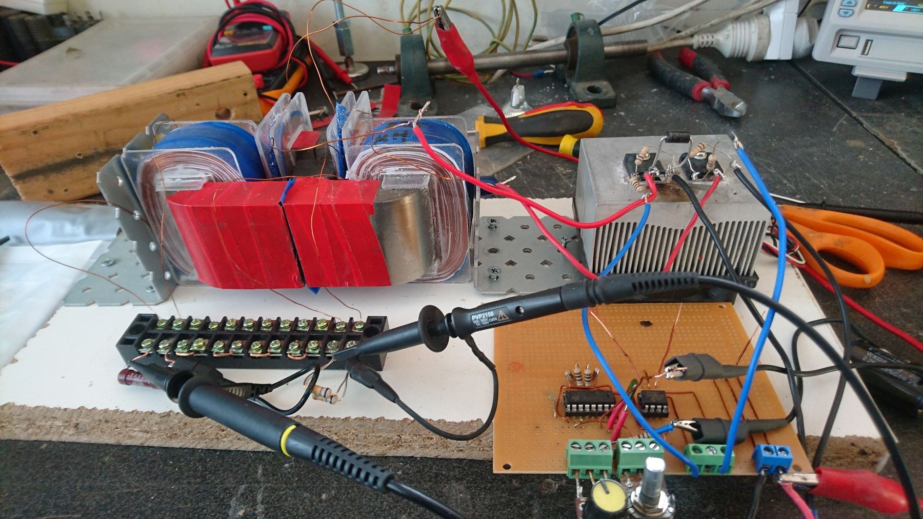
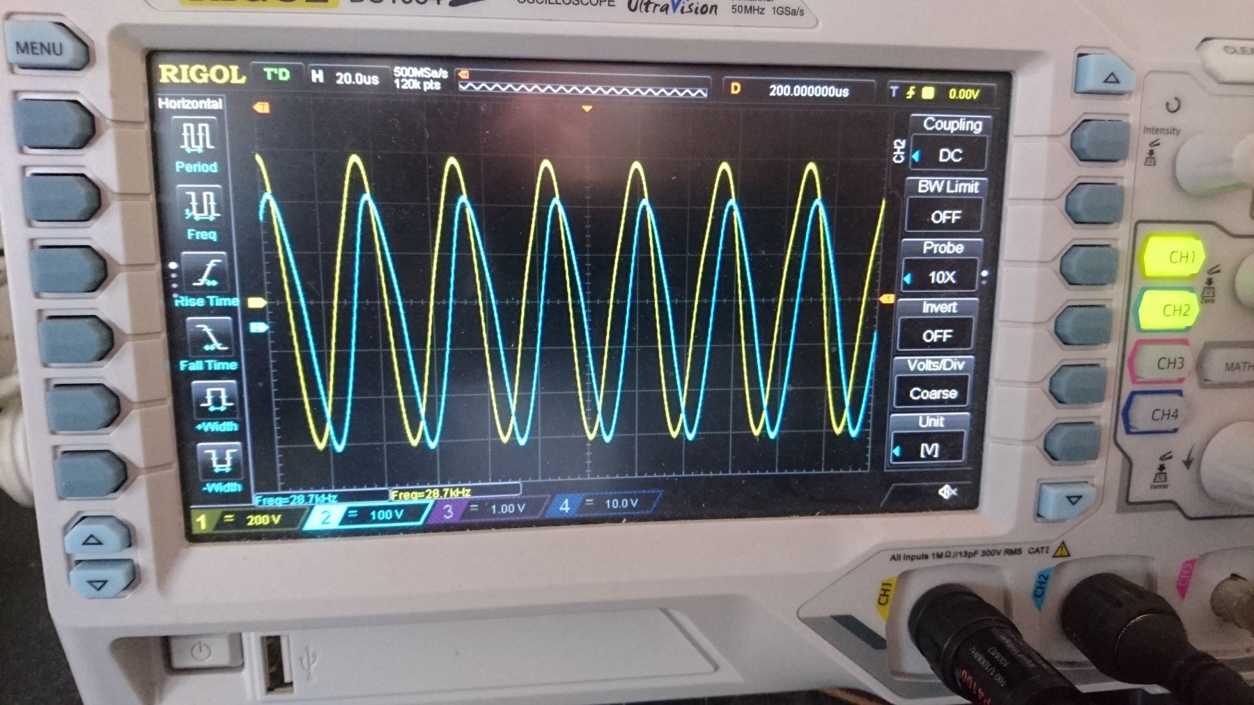
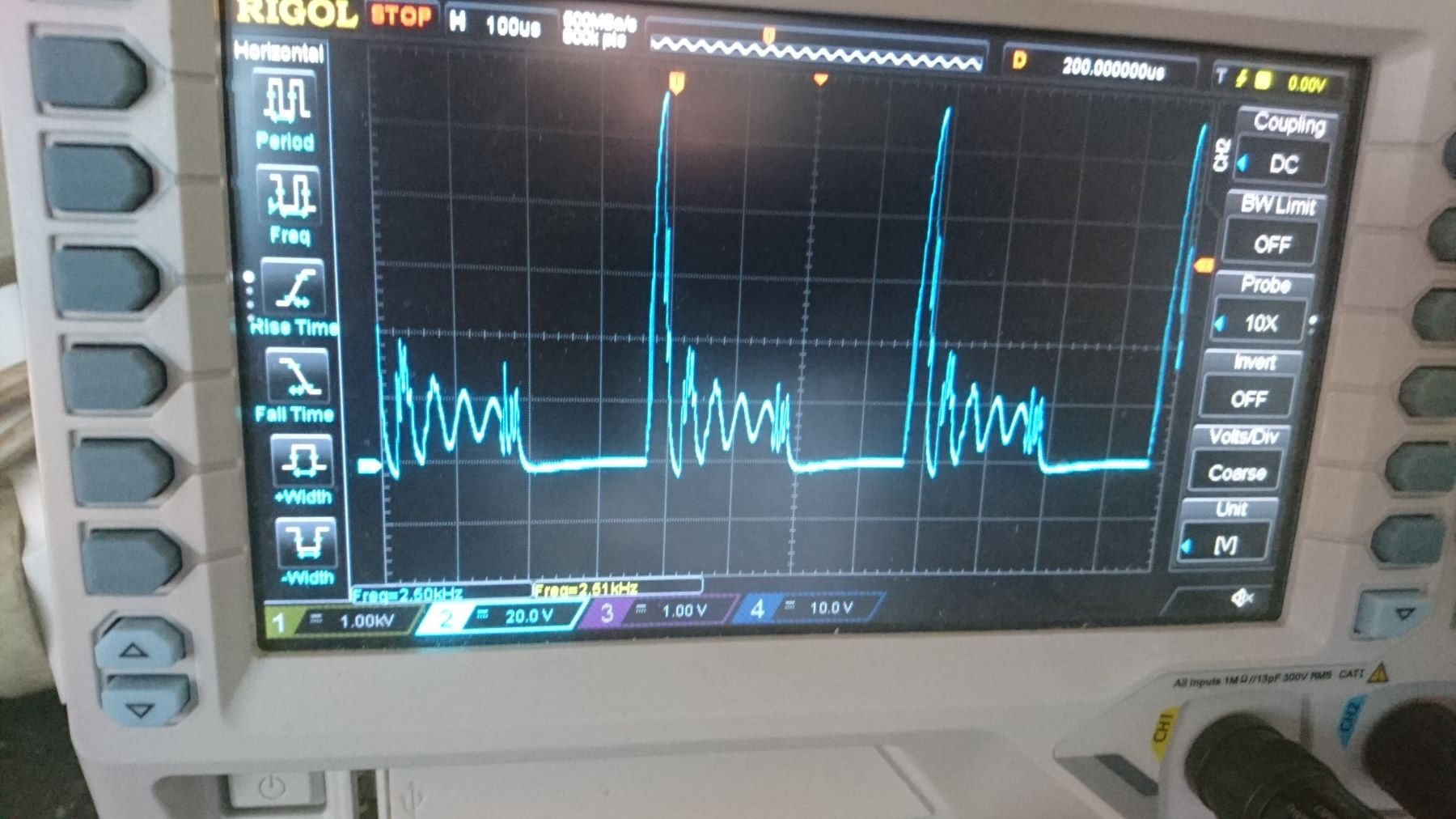
                Have eventually got my Meg replication built!!. Winding the secondarys' took a bit of time getting them wound smoothly with the fine wire. Anyway, these are my first photos and first connection! Have not looked to see if my coils might need swapping yet. The Yellow trace is a 100:1 probe the Blue trace is 10x probe. The yellow trace is on the CCW coil. At least i think it is CCW, always get a bit confused with the winding direction. Showing just over 1kv.

Incidentally, i have put a thin plastic separator between the C sections.

So this works!  I shall look at it for a short while to see what it tells me. Reassuring that I can build something that works!.

Regards

ourbobby


chocolate blanco posted this 08 April 2020

very good, could you pass the circuit and how many turns on each coil? You say that with a better cable, like coax, would it improve?

  • Liked by
  • Chris
  • Augenblick
Ourbobby posted this 09 April 2020

Hi Chocolate blanco,

                                  I am using the coil dynamics of JL Naudin's replication of the MEG. http://jnaudin.free.fr/meg/meg4cf.htm

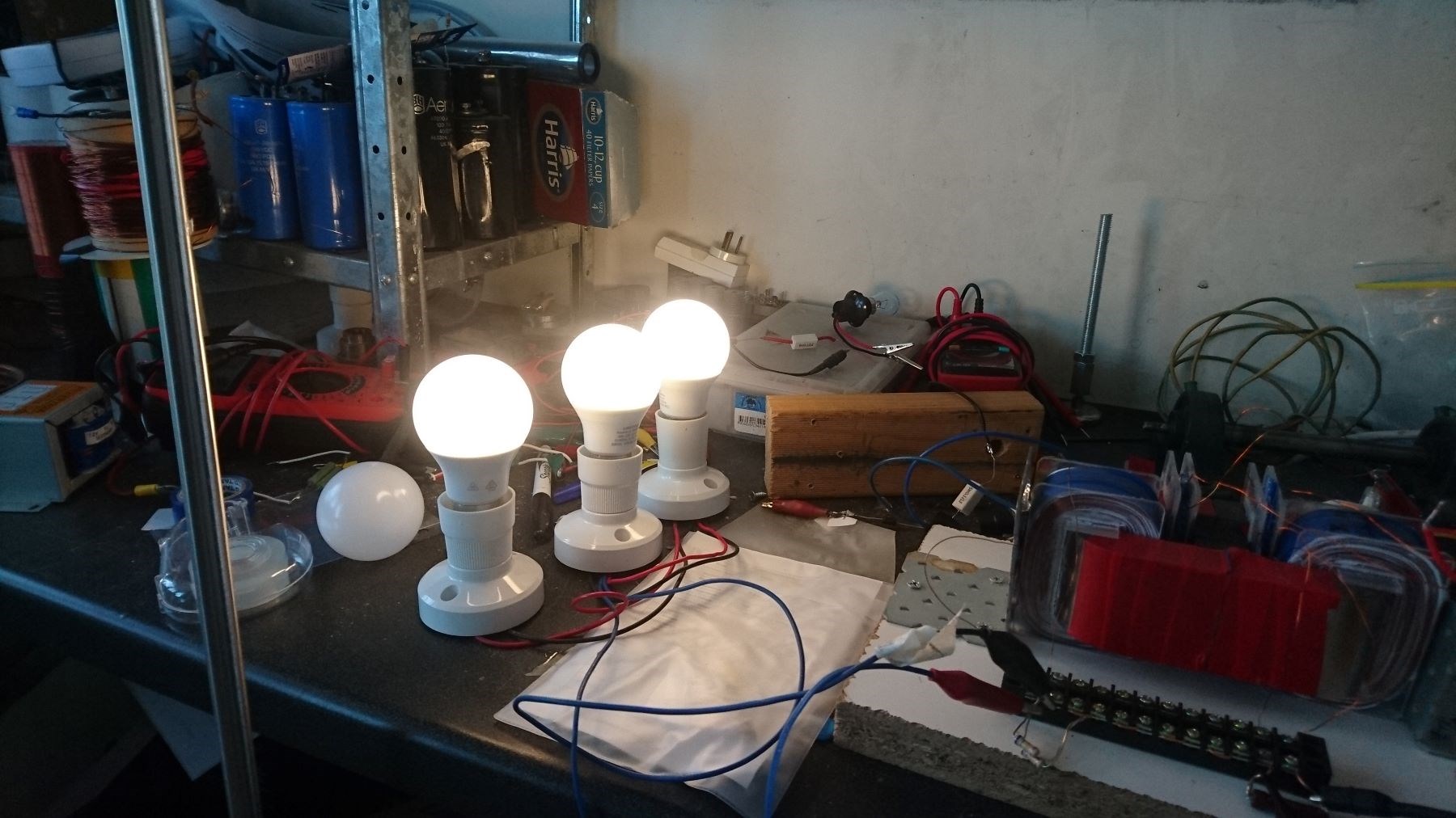
for the driver I am using the circuit outline as postrd above using a 3524 and 4227 driver. I have been looking at my coil connections and something unusual has occurred. I have found that general pulsing with my circuit will not provide sufficient oomph for the bucking to occur. I think I have a tricky potentiometer! Because, when I get to a certain point of the wiper, I get very good pulse to the coils! As it is a tricky circumstance, it is very difficult to maintain the pulse outcome. This has indicated to me that I must reassess the drive for the coils in the unit. I am not sure if the pulse output is what I might be looking for. The globes in the attached photo are the mains voltage LED's. So they will light with Radiant output. Incandescent Globe does not light up! So i am still not doing it correctly. The voltage i am using is 12v battery.

Regatrds

ourbobby


Chris posted this 09 April 2020

Hey Ourbobby,

We have a The MEG Thread. Its worth watching the Video if you have not already:


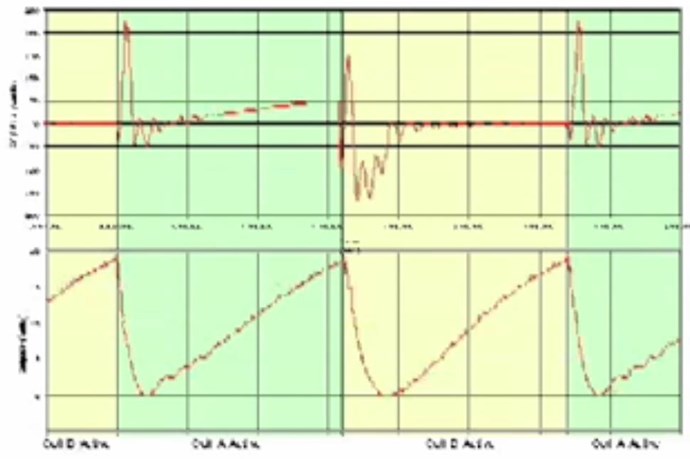
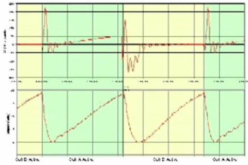
Notice the waveform shown:


Of course the bottom waveform is upside down.

I hope this is useful!

Best wishes,

   Chris

  • Liked by
  • Fighter
  • Augenblick
Ourbobby posted this 09 April 2020

Hi Chris,

              Thanks for that Timing link. I 'll order some MOV's tomorrow with different voltages, so i can see what my outputs are. I think i have the correct waveform but wrong control process. I get funny buzzing sound from within the core when i get the tricky bit stabilised. Although in reality I likely have just fluked the right potentiometer resistance to switch the coils?  That's what can happen when experimenting.

Will take a few days to arrive i think, even a week or more. Then sanitising! Strange times are here.

I built the MEG to see if it would help me understand the process we are sharing on overunity. Incidentally, if I hold one of my mains voltage LED globes towards the MEG, it will attempt to light up!

Regards

ourbobby

  • Liked by
  • Chris
  • Augenblick
Chris posted this 09 April 2020

Hey Ourbobby - No no, just use diodes as we have been.

We are getting the same result, we only need improve on it.

Good work keep it up.

Best wishes,

   Chris

  • Liked by
  • Augenblick
Ourbobby posted this 10 April 2020

Hi Chris,

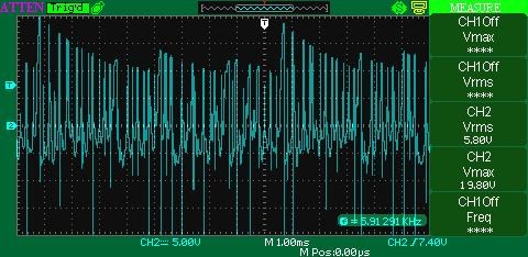
               I am having difficulty getting the sawtooth. I am thinking that with the two coils L1 and L2, one should be disconnected. I am getting too many erratic wave forms. Even with one disconnected I do not seem to be able to see the current wave form. Is it possible I am not generating enough current. I am recording 30ma into the secondary coils.

regards 

ourbobby

  • Liked by
  • Chris
  • Augenblick
Chris posted this 10 April 2020

Hey Ourbobby,

Don't worry, this is common, its something we all go through.

The best thing to do is start at the start again, the 1, 2 and 3 protocol.

  1. Check input Coil, all other Coils disconnected. Make sure its switching properly.
  2. Connect and Load the Secondary Coil, load it in the Forward Direction. As this Coil is loaded, the input will go up.
  3. Connect the Tertiary Coil. Load it in the reverse direction. Loading this Coil, the Input should go down.


We just have to remember the basics we learnt in the last video series: Non-Inductive Coil Experiment. In the MEG configuration, I have recommended putting the Input over one of the Output Coils.

Best wishes,

   Chris

  • Liked by
  • Augenblick
  • ISLab
Ourbobby posted this 10 April 2020

Hi Chris,

              Thanks again for the feedback. Under a bit of pressure at the moment. I will, restart and follow the rules!

Regards

ourbobby

  • Liked by
  • Chris
  • Augenblick
Chris posted this 10 April 2020

Hey Ourbobby,

Take your time, we live in tough times so no pressure this end! Only when you have time!

Best wishes,

   Chris

  • Liked by
  • Augenblick
Chris posted this 11 April 2020

My Friends,

I was having a conversation with a Friend, about Coils and Turn Direction. I would like to share my thoughts.

I have shared many images on this subject:


Others also.

Documentation is super important! Make your Coils Modular, so one Coil can be removed and re-wound the opposite way if necessary. Document the Turn Direction vs the Output! This is where you will have the best success. I have pointed this out before: here.

Don't put too much pressure on yourself!

Take your time, learn as much as you can learn, the rest will come in time! Reference and Cross Reference as I may not always be 100% Right, I have done my utmost to get you accurate correct information, but sometime my interpretation is just that, my interpretation.

Learn from those before us:

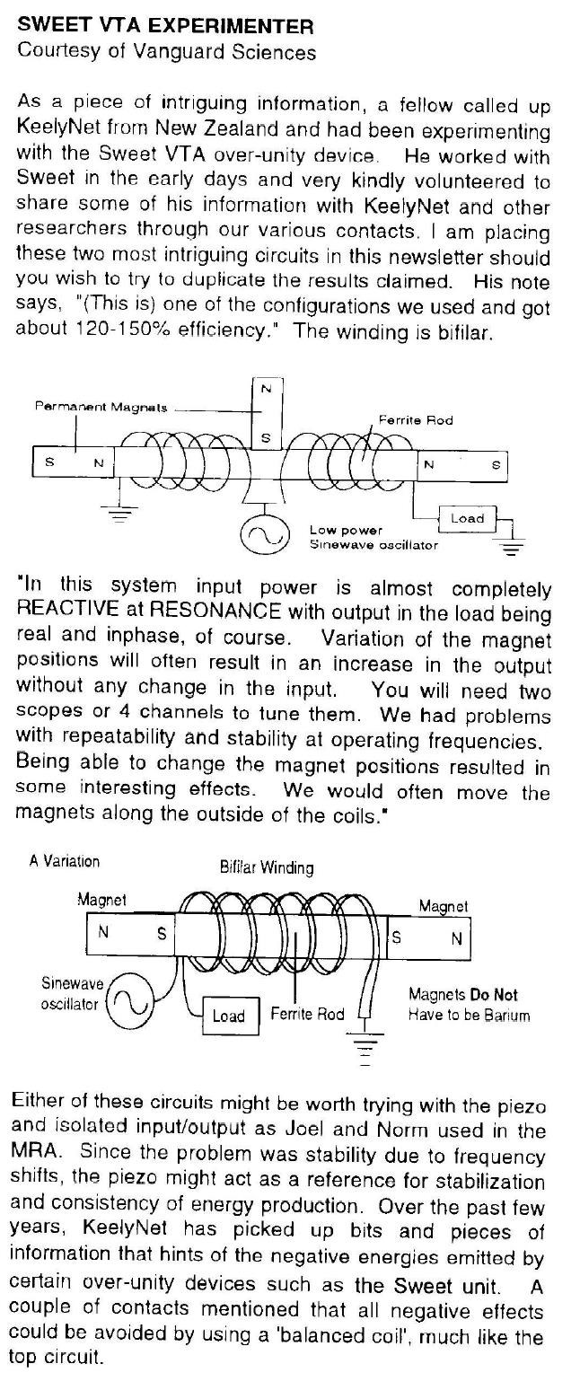
Consider for a moment the construction of the triode which includes the bifilar coils located within the fields of the two conditioned magnets. 

When the current in one half of the conductors in the coils (i.e., one of the bifilar elements in each coil) of the device is moving up, both the current and the magnetic field follow the right-hand rule.

The resultant motional E-field would be vertical to both and inwardly directed.

At the same time the current in the other half of the conductors in the coils is moving down and both the current and magnetic field follow the right-hand rule.

The resulting motional E-field is again vertical to both and inwardly directed.

Thus, the resultant field intensity is double the intensity attributable to either one of the set of coil conductors taken singularly.

Expressed mathematically:

E = ( B x V ) + ( -B x -V ) = 2 ( B x V )

Ref: Floyd Sweet - Nothing is Something.


Now, I urge all to study this intently! It is extremely Important! What are we looking at? Notice B is considered TWICE, as is V!

If the directions of the two signals are such that opposite H-fields cancel and E-fields add, an apparently steady E-field will be created. The energy density of the fields remain as calculated above, but the value of the E-field will double from E / 2 to E.

Ref: Floyd Sweet - Nothing is Something.


What is this? Exactly what is this? Study this, make the connection:


Lets make this Vertical, to match the Description above:

This is SO Important! Once understood, it is the Game Changer, Doors open and the World will change forever!


REMEMBER: 

The VTA "likes" to always see a minimum load of 25 watts.

Ref:  FLOYD SWEET'S VTA UNIT - by Walt Rosenthal


Please don't let opportunity pass you by! What I am sharing is world changing! We are Light Years Ahead of the other Forums!

Best wishes,

   Chris

Chris posted this 13 April 2020

My Friends,

Right now is a good time to do experiments. Many of us are at home, in lock down.

I want to share something I have seen over the years, this is an indication of Success vs Failure. The Jet Engine:


Now compare to these guys:


If you wish, you can go watch their videos, they are good, good quality builds, but you will see, many tests and they don't have any success!

They don't achieve a running Jet Engine!

Why?


It is the same in our game! We have successes and we have failures! But it is really important we don't give up!

Whats the most important thing? Learn as much as you can from every experiment! Learn WHY it doesn't work, which is what I tried to show in my series 1 = 11 starting here:


Find where the problems lay! Solve the Problems, treat each problem as a challenge!


Hi Ravio, My Friends,

This post is very Important! Please read and understand!

What you bring up has valid points!

You have 10% ON and 90% OFF in input. I have seen this power triangle explanation, but don't you think that in 10% you have already paid for what is happening in the rest of 90%?


In all conventional Transformers, Energy is Transformed, Input is Transformed to Magnetic Force to Output Force, the M.M.F, or Ampere turn is equal and opposite less losses. Input M.M.F is Equal and Opposite to the Output M.M.F less Losses! Any time you offset the M.M.F, force, then you have more work in the System. 

This is the point of the Machine we build, to Offset the Input to Output M.M.F, to add M.M.F via the Third Coil!

Yes, it can be that these Waveform's can have Conventional Transformer Transformations, but we are not building a Conventional Transformer, that's the point of what we are doing.

Someone tested some Melnichenko patent (some LCR circuit) and figured out that 1/4 (quarter) pulsing was beautiful - looks like you have 3 rising waves during ON and the rest 10+ are at decline. Measuring input and output (on resistor R) - revealed that there was nothing there.


A great deal of experiments performed by others are invalid, until one understands the Subject matter and thus the foll operation of a machine, experiments can be completely inconclusive! I have done many experiments that I look back on and think to my self, there is no way that could have worked, I did not understand the machine, if the slightest deviation in the Experiment you are performing from the original experiment, then the experiment is wrong. So we really can not compare unless we have everything 100% Correct and can verify that.

Th waveform you show, is not like any Andrey Melnichenko Experiment Waveform I have ever seen and thus can not comment on its validity or verification.


You have to measure input and output on resistive load, wave shape does not give you full info. Of course - wave shape shows you if you have ferro/wave/accousting/stochastic/whatever resonance.


I always use Resistive Loads, an Incandescent lamp is largely a Resistive Load, this means Power is real, Voltage and Current are in phase - Yes.

It is correct to ask questions! No one should believe what might be ramblings of a crazy person! I expect all members to question everything, after all that's our job, in Research, is to question everything, until we understand it, totally and fully!

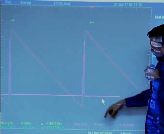
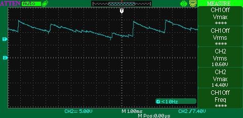
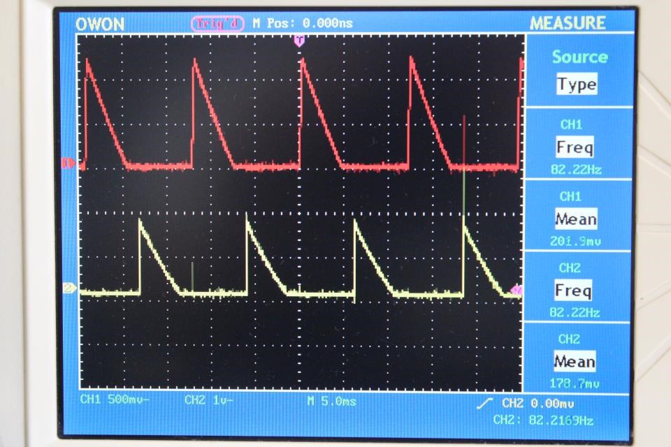
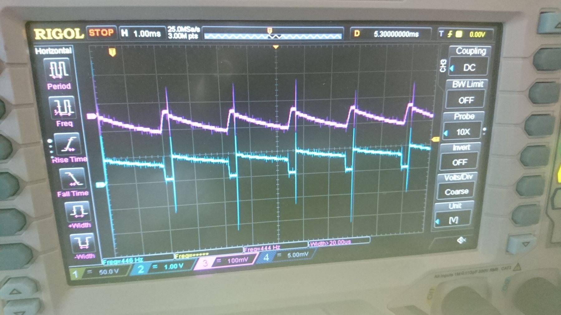
The Sawtooth waveform can be both Below Unity and Above Unity! Some examples I have given here on this forum, Don Smith, The MEG Team, Graham Gunderson, Tinman aka Bradley Richard Atherton:


The Sawtooth Waveform is the Defining Lenz's Law Waveform!

I pointed out in my thread: Some Coils Buck and some Coils DONT why the Sawtooth Waveform is so important:

The Sawtooth Waveform is the Result of Lenz's Law, the very fact that Two Magnetic Fields are working together! This Magnetic Field Interaction is CRITICAL to understand! It is the EXACT Same effect as dropping the Neo Magnet down the Copper Tube:


This is the reason the waveform has a Linear Decay, not an exponential decay! A Critical fact to observe and understand! 

The Sawtooth Waveform is the Defining Waveform for Energy "Generation"!

Best wishes,

   Chris


Please everyone, I cant do this without you! We have to do this together! I was so hoping to see more experiment by now.

Best wishes,

   Chris

  • Liked by
  • Jagau
  • Augenblick
Ourbobby posted this 15 April 2020

Hi Chris, 

              I am running a small set-up for bucking coils. I am controlling the voltage and current to the coils. Volts in is 1.5v at 60mA. I get it running for a few moments and then my mosfets have blown! Certainly not due to high import volts or current! I don't even get to see the reaction on the scope. The only thing i can think of is that when slapping starts, the feed back to the primary, although transformed to low voltage becomes high current, hence the blown fets.

Is this explanation plausible?

edit: I have reverse pulse diodes connected across the fets. These are still OK.

regards

ourbobby.


Chris posted this 15 April 2020

Hi Ourbobby,

Would you mind drawing a circuit and posting an image?

Anything is possible, but it would be easier to try to solve with a bit more data. Blown Fets is an issue! They get expensive!

Your Coils are loaded? Whats the load?

Best wishes,

   Chris

  • Liked by
  • Augenblick
  • chocolate blanco
chocolate blanco posted this 15 April 2020

Hi guys, how are you doing? You know that the high frequency is due to a loop, I mean when you build a bucking coil and connect it in series, the wires cross, I mean an 8 is formed, that's the infinity loop, I don't have time, it is timeless, that It is high frequency, the same thing happens in the pancake coil of tesla, in the POE, in the Rodin, in all those that their fields oppose and are in series, that forms the symbol of infinity in the coils and generates that the pulse of low frequency becomes high frequency, that happens on my coils too

  • Liked by
  • Chris
  • Augenblick
chocolate blanco posted this 15 April 2020

It is also that when the waves collide and when producing standing waves what happens is that I tune the high frequency, because when the magnetic and electric wave collide, the magnetic wave stays down because its particles are heavy and the electric wave is light and It moves fast, so the wave is not influenced by magnetism, and it is easier to tune, the glass radios that are without batteries work with a bucking coil and that gives more Q, that means that they tune better, we with the bucking coil is producing a high frequency signal to tune high frequency that in a bucking coil that generates a lot of voltage thanks to the lack of magnetic brake

Chris posted this 16 April 2020

Hi CB,

You have a very good understanding on this Tech!

I have to say, and there is a lot of talk about this, the Electric Field, Floyd Sweet spoke of the Motional E Field, the Motional Electric Field, and described it in great detail in many of his documents, one such example here:

The source of energy is unlimited, the virtual vacuum of space itself structured by a motional electromagnetic field is the powerhouse.


...


THE MOTIONAL E-FIELD
Of all the known fields- electric, magnetic, gravitational and motional E-fieldthe only ones incapable of being shielded are the induced motional E-field and the gravitational field. The nature of the motionally induced electric field is quite unique; in order understand it more fully we must start by parting with a few misleading paradigms. When magnetic flux is moved perpendicularly across a conductor an electromotive force (E.M.F) is electromagnetically induced "within" the conductor. "Within" is an artefact of the commonly used analogy comparing the flow of electric current within a wire to the flow of water within a pipe. This is a most misleading model theoretically. The true phenomenon taking place has little been thought of as involving the production of a spatially distributed electric field. We can see that the model's origins likely arose from the operation called "flux cutting", a most deceiving and misleading term. A better term, "time varying flux modulation", does not imply any separation of lines of flux. Truly, lines of flux are always in closure upon themselves and are mathematically expressed as line integrals. It is fallacious to use the term "cutting", which implies time varying separation which does not in fact ever occur. A motionally induced E-field is actually created within the space occupied by the moving magnetic flux described above. This field is present therein, whether or not a conductor is present in the space.

Ref: Floyd Sparky Sweet - Nothing is Something.


What I always try to take away, is, the fact that we can not separate the two, there is always an Electro and a Magnetic Field. Although we might think the Magnetic Field is no longer there, it is still there. Its just hidden, or the vector Sums to Zero, but we still have the Magnetic, it must always go with the Electric, to make up the Electromagnetic Field.

One is the orthogonal Component of the Other, they really are one and the same thing. I enjoy what Sir Richard Feynman said about the Motional Magnetic Field: 


Of course the only time we have Electric and no Magnetic is when the Electric Field is Stationary. We all know a Motional Electric Field is going to have a Magnetic Component also.

I know Vidura may not agree with me on this and I would like to hear what he may not agree with, as this debate is truly a very interesting one!

Best wishes,

   Chris

Ourbobby posted this 16 April 2020

Hi Chris,

              I bought a bunch of IRFP460's on ebaya while back. Looks like most are dud! I suppose one gets what one pays for? I have sorted through them an found a few that seem to measure ok. As a result here is my latest result. To get this, I have to measure across a much larger resistance than in Video 7 and the 0.1 ohm. Also I can get an output with a dimmed light from a 60w incandescent 240v globe. Reassuring. all I have to do now is understand how to manage the winding to produce a greater current!!


Regards

ourbobby

Vidura posted this 16 April 2020

Hey Chris,

As reply for the Subject:


What I always try to take away, is, the fact that we can not separate the two, there is always an Electro and a Magnetic Field. Although we might think the Magnetic Field is no longer there, it is still there. Its just hidden, or the vector Sums to Zero, but we still have the Magnetic, it must always go with the Electric, to make up the Electromagnetic Field.

In my present understanding I would agree to say that all the physical universe is one and the same thing, as it arises from one unique cause, and in this sense magnetism and electricity, even fire and water are one and the same thing. But from the perspective of our perception there are three forces concatenated, all three having a distinct field and vibration, and are orthogonal to each other. I will soon do a couple of videos with simple experiments, which will give reasons to re-think about some "laws" which we have taken for granted. 

Best wishes,

Vidura


Chris posted this 16 April 2020

Hey Vidura,

which will give reasons to re-think about some "laws" which we have taken for granted.


I agree, we do, and I believe we currently, I mean Science, does not currently understand the Forces correctly. I think Graham Gunderson said we use the Forces, Magnetism and others as a convenience, its just how we currently understand the Forces but they are not real. I believe the book Graham was referring to was Collective Electrodynamics by Carver Mead.

Floyd Sweet said:

As postulated by Einstein in his famous equation E = MC2, energy is a kind of matter.


We have a very obvious relationship, perhaps over time, science will understand this better and the whole thing is very much simpler than we have been led to believe.

Best wishes,

   Chris

Ourbobby posted this 17 April 2020

Hello Vidura,

                     I find your comments on the infinity loop intriguing! So I have connected in series a set of bucking coils that I have wound to create the infinity loop. I have driven it with a primary coil wound on top of one of the bucking coils. So I have Primary=CW wound and Bucking coil1 CW wound and Bucking coil 2 CCW.. I am able to extract some energy with resistive load across the loop. However, when in operation, I am drawing minimum current, even at the Drain of mosfet. After say ten minutes, heatsink and mosfet is able to cook fried eggs!! I turn off low voltage connection to Drain, (Not disconnected!), and it keeps running. So energy is being fed back through Primary (now Hot) to mosfet. When no load, Still get high heat transfer!

So am I driving it wrong,  or is the configuation a theoretical proposition?

Edit: Glass radio - Crystal radio! I am a bit slow at times!!

Regards

ourbobby


Atti posted this 17 April 2020

Some thoughts ....  

Chris posted this 17 April 2020

Welcome back Atti!

@Everyone, I have invited Atti to come back, we have had a discussion and we have come to an agreement.

Welcome back and Thank You for sharing Atti!

Best wishes,

   Chris

Ourbobby posted this 18 April 2020

Hi Atti,

             Impressive! I am struggling to decipher parts of your circuit. Would it be possible to get a circuit diagram?

Thank you

ourbobby

Atti posted this 18 April 2020

Hi Ourbobby.

I'll send it to you anyway! But it will take some time.

Atti.

Ourbobby posted this 18 April 2020

Hi Atti,

            Thanks

ourbobby

Ourbobby posted this 19 April 2020

Hi Atti,
It look to me as if my bucking coil test has a similar outcome to yourself. The exception being that you get a greater energy output. It is a confusing experiment in as much as that one can see that the standard electronics logic does not appear to fit. With my outcome, as long as I have a connection to the Drain of the mosfet, then the coils will oscillate and energy can be extra ted. I have two voltage supplies. One to supply the mosfet gate and a separate supply to supply voltage to Drain of mosfet. It is when I switch off the supply to the drain that the coil still operate and the globes still light that is the puzzle. If I disconnect the battery supply to the Drain, well the energy production ceases. So it would seem that all that is required is a positive supply connection to the Drain. In my case a negative battery terminal. However, as the battery is switched off, why does the system work?

Another observation is the ringing sound emanating from the coils! Very similar to the pitch evident on your video demonstration. I have rewound the coils for size of windings - up and down - and reset the pulse frequency range in an effort to move higher in frequency out put. To no avail! I would conclude that this is a point of interest that I should understand. But how so? When no current is being consumed through the drain, and the frequency becomes a natural setting, how do I find out the way forward? The ringing is likelyl set to the core density, so becomes a fixed item. But the voltage, well that is another issue.

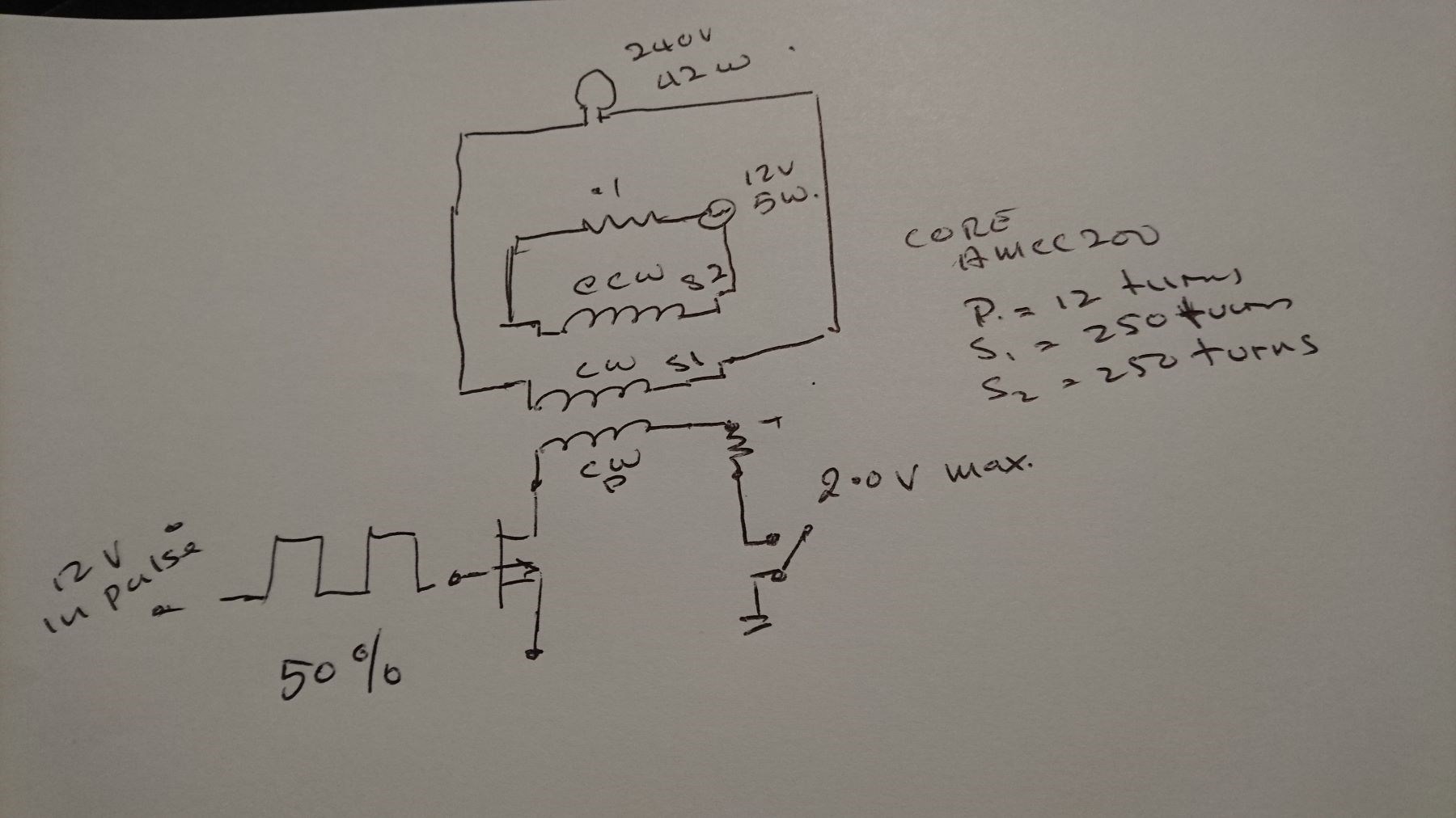
Here is my simple experiment. the core is an AMCC200

Regards
ourbobby

Chris posted this 19 April 2020

My Friends,

All of you are doing real good work! I congratulate all of you on your awesome efforts!

Some things to help:

  1. Gap your Core. If you have no Gap, then Increase the Gap, if you have a Gap, try reducing it.
  2. Turn your input up in little steps, then test.
  3. Check the delay in your Conduction, using a small circuit you can increase or decrease it, Time Delay.
  4. Make sure your Magnetic Fields are Interacting correctly, the right polarity, Secondary opposes the Primary, Tertiary opposes the Secondary but assists the Primary.
  5. Remember, the Change is Magnetic Fields Creates the Voltage, find the Maximum Amplitude of the Voltage! Think Magnitude or Amplitude!
  6. The Maximum Torque, or M.M.F, Opposing Forces, must mostly occur between the Secondary and the Tertiary Coils - Not Primary Coil.
  7. Find the Resonant Frequency, Magnetic Resonance, the is is related to Maximum Amplitude Voltage.
  8. Keep trying, don't ever give up, lets work together on this until we solve every problem!
  9. Ask questions, we all can help each other...


My Dear Friends, Together we can solve this! We know this works:


Don Smith:


The MEG Team:


Tinman:


Graham Gunderson:


My Work:


My Friends, stick to the Facts, stick to the simple facts. Stick to the Energy "Generation" way of thinking. Force your mind to think simple, don't over complicate this.

Remember: Ohms Law: I = V / R, increase V and R stays the same then I must increase!

Best wishes,

   Chris

Atti posted this 19 April 2020

Hi Ourbobby and everyone.

(I'd like to say something again. Unfortunately, I don't know English. It's my fault! But if the google translator translates aside, I don't pass on what I want to communicate, it's no longer my fault! Still, I try to be careful.)

Ourbobby
I don't understand something. Why is the winding that way?
Why is the unwinding not on the two columns why is the two columns joined together (covered with black insulating tape)?
Can you make a short video of this? Or drawing?

Yes.
-The frequency is low. Multiple speeds are low frequency.
-Co winding direction for one column and ccw direction for the other column.
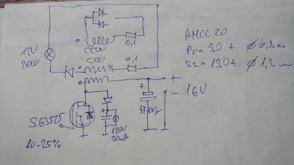
-In short but essentially the drawing is attached.
-The power supply is from a separate circuit and the control is separate.
  -The negative wires of the two power supplies are connected!
-Drive the Fets or the timer (SG 3525 or 555 or whatever) from another circuit. It has a current consumption of about 50-300mA. I don't think exactly.
-A small light bulb tied to the feet of the Fet Drain just as an optical guide. Or it would be used to drain very high spikes.
-The air gap between the two C-shaped cores is frequency dependent!
-While there is a high load (high current) on the L2 coil at very high frequency, there will be no high current in the L3 coil. So there will not be enough feedback. From this, I think (my next study will focus on this) that no AMCC core is needed. Conventional transformer iron or hypersilicon can also be good. True, the best of these is to look for a "musician."
Listen to your voice at 0:15  

-The diode polarities do not change much for coil L3, but if the connection direction is changed for coil L2, the situation is different.

My next study was on d.c. it will be similar to measuring motor current. So the transformation is a study of the changes between L1 and L2, respectively. Especially what happens during the break. The sawtooth wave can be easily removed when the d.c motor is running or rotating.

For everyone else.
What happened happened. I'm not going to explain it to anyone. Everyone thinks of me what they want. Point.


Nagy Attila.

Atti posted this 19 April 2020

I forgot the drawing drawing.

Chris posted this 19 April 2020

Atti - Thanks for sharing!

You are a respected member on this forum!

I know we have had translation difficulty's with Google in the past, we try to over look that - So don't worry ok! Please don't delete the work we reference, its all important. All of it is important, we will see, soon how important!

Thanks for Sharing!

Best wishes,

   Chris

Ourbobby posted this 19 April 2020

Hi Atti,
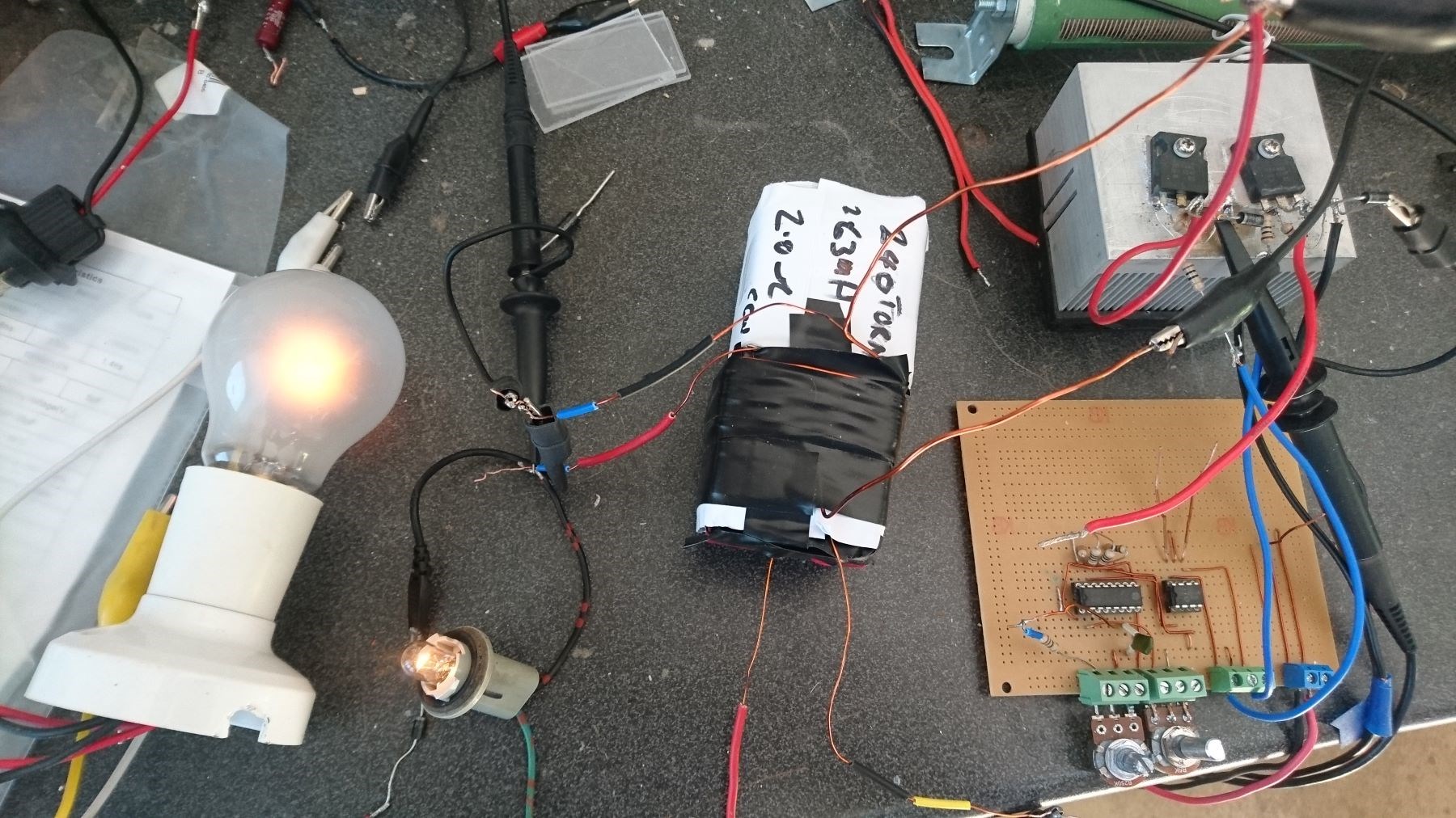
Here is the circuit I was using. Too simple when I look at your circuit. The concepts at the moment that I am not getting with this circuit are, 1) whether I switch the voltage on or off to primary coil, I still get the same output. 2)As there is no voltage to the Drain, how do I get upwards on 5Kv output across the bucking coils.3) If I connect S1 and S2 in series, then my disconnected mosfet becomes very hot, subsequently if I run the S1 and S2 as separate coils then I get two outputs and no heating of mosfet.

It is interesteing that on my meters I am reading 90uT and frequency upwards of 540K. Yet My bucking coils are ringing out around 2kc's. Very challenging!

On the coil winding. I have wound across each C section of the cores. The paper and tape are for support. With this method I am easily able to test for variations on induction due to gap changes., Also, they are easier to mind when I do not have many bobbins. There seems to be no difference in output when wound on a bobbin that sits acroos the two cores and winding on each individual core. I await correction to my observation on that point.

Regards

ourbobby

Vidura posted this 19 April 2020

Hi Ourbobby, really puzzling what is going on in your experiment. If I may suggest to post some scope shots of mosfet gate, MOSFETs drain separately, with and without power supply connected, so we might find out what is going on. I didn't understand what you referring the measurement of 40uT to? Are you feeding a signal of >500khz and coils oscillating at 2khz, is that so? Regards Vidura.

Ourbobby posted this 20 April 2020

Hi Vidura,

               Here are some photos of the current set up. My previuos one, as discussed with Atti used .4mm wire and began shorting within the windings. This set-up, which gas the same characteristics and layout uses smaller turns on winding S1 and S2. Here are the images you requested.

Bucking coils scope shot of mosfet Drain connection no voltage applied, but connected to battery.

Input drive to gate

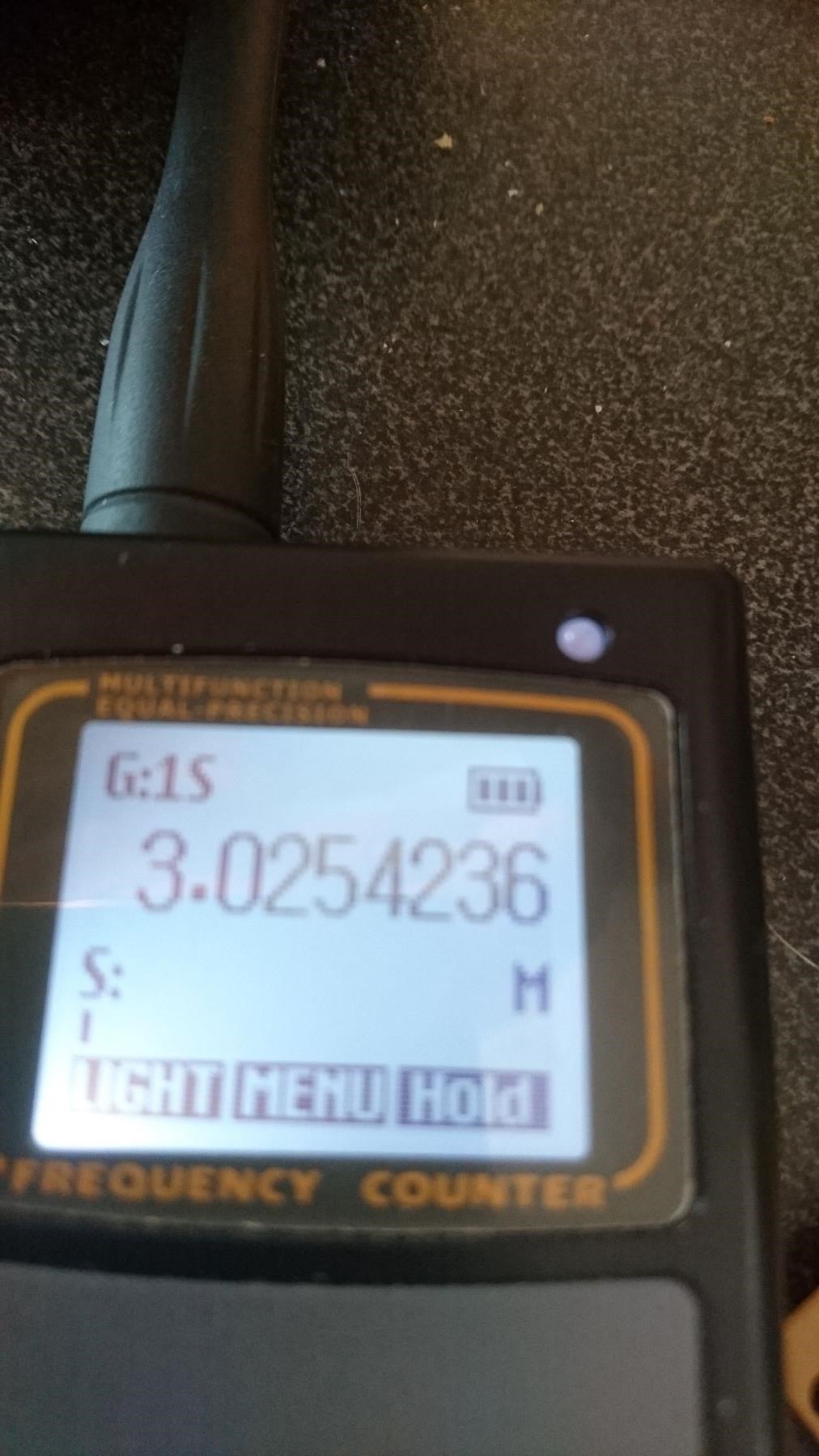
My EM meter, on previous coil was showing 90uT, This coil much lower output 3MHz

Frequency counter on High range showing

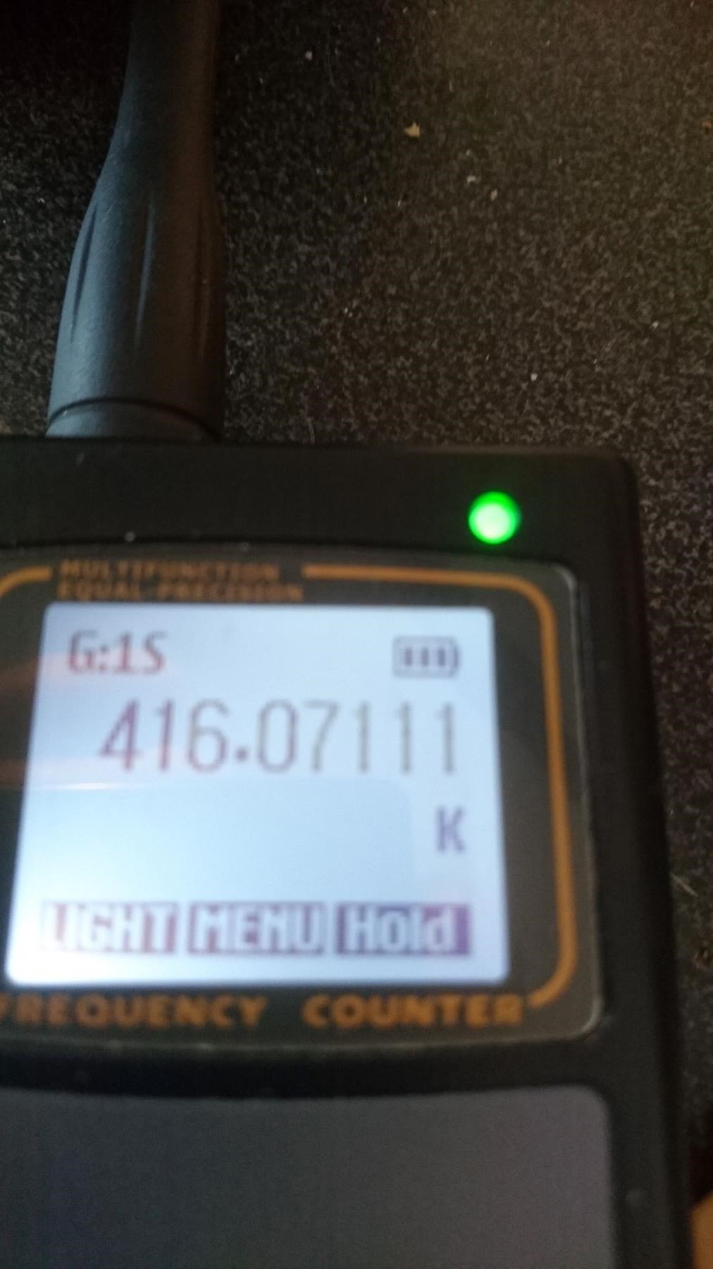
Frequency  counter on low range showing 416 KHz

This is the set-up as per the circuit in previous post

This is a scope shot across the load from S1 coil, showing 5Kv.

If I disconnect power to mosfet, there is no output. Nothing to show on scope except straight trace. I am using two independent batteries.

Regards

ourbobby

Ourbobby posted this 20 April 2020

hi Vidura,

               No magic or Puzzle!. I have a faulty variable voltage supply! Reding 2v but supplying 12v straight from battery!


My apologies. 


ourbobby

Atti posted this 21 April 2020

Ourbobby.

Too simple when I look at your circuit.

What else do you think should be added to keep it simple? Why is it wrong if it's easy?

Chris posted this 21 April 2020

My Friends,

Atti, an excellent point:

Why is it wrong if it's easy?


If it is easy, then you understand it. This is the goal and why I have done this over such a long drawn out period, for the greater spread spectrum understanding of this tech.

I would like to share some quotes:

  • Testing leads to failure, and failure leads to understanding.


  • Research should be defined as, doing something, where half of the people think its impossible, impossible! And half of them think, ehr, maybe that will work.


  • When there's ever a break through, a true break through, you can go back, and find a time period when the consensus was, well that's non-sense! So what that means, is that a true creative researcher, has to have confidence in non-sense!


Ref: Burt Rutan - Famous Aircraft Designer


Best wishes, stay well and safe!

   Chris

Ourbobby posted this 22 April 2020

Hi Atti, 

           I am not saying your circuit is simple. I am saying my circuit is simple! You have developed avenues within your circuit. I have only made the basic model to get proof of concept. I am not critising your circuit, I am complimenting it.

regards

ourbobby


We're Light Years Ahead!
Members Online:
What is a Scalar:

In physics, scalars are physical quantities that are unaffected by changes to a vector space basis. Scalars are often accompanied by units of measurement, as in "10 cm". Examples of scalar quantities are mass, distance, charge, volume, time, speed, and the magnitude of physical vectors in general.

You need to forget the Non-Sense that some spout with out knowing the actual Definition of the word Scalar! Some people talk absolute Bull Sh*t!

The pressure P in the formula P = pgh, pgh is a scalar that tells you the amount of this squashing force per unit area in a fluid.

A Scalar, having both direction and magnitude, can be anything! The Magnetic Field, a Charge moving, yet some Numb Nuts think it means Magic Science!

Message from God:

Hello my children. This is Yahweh, the one true Lord. You have found creation's secret. Now share it peacefully with the world.

Ref: Message from God written inside the Human Genome

God be in my head, and in my thinking.

God be in my eyes, and in my looking.

God be in my mouth, and in my speaking.

Oh, God be in my heart, and in my understanding.

Your Support:

More than anything else, your contributions to this forum are most important! We are trying to actively get all visitors involved, but we do only have a few main contributors, which are very much appreciated! If you would like to see more pages with more detailed experiments and answers, perhaps a contribution of another type maybe possible:

PayPal De-Platformed me!

They REFUSE to tell me why!

We now use Wise!

Donate
Use E-Mail: Chris at aboveunity.com

The content I am sharing is not only unique, but is changing the world as we know it! Please Support Us!

Thank You So Much!

Weeks High Earners:
The great Nikola Tesla:

Ere many generations pass, our machinery will be driven by a power obtainable at any point of the universe. This idea is not novel. Men have been led to it long ago by instinct or reason. It has been expressed in many ways, and in many places, in the history of old and new. We find it in the delightful myth of Antheus, who drives power from the earth; we find it among the subtle speculations of one of your splendid mathematicians, and in many hints and statements of thinkers of the present time. Throughout space there is energy. Is this energy static or kinetic? If static, our hopes are in vain; if kinetic - and this we know it is for certain - then it is a mere question of time when men will succeed in attaching their machinery to the very wheelwork of nature.

Experiments With Alternate Currents Of High Potential And High Frequency (February 1892).

Close