Hello Everyone:
This is my first time to post on the form, and it's my great honor to be here. I too like everyone here want to see humanity able to have free energy for everyone, thus we can stop the pollution and global warming.
I want to share some of my experiment step by step, and the problem solving process, I will share as much and as details, thus the newcomer to this technology like me, will learn from my experiences and mistakes, and make sure their study and replication process a lot easier. I have not make it working yet, many problem need to discuss and solve, thus I will keep update.
l recently decide to replicate the Akula Lantern number 4, which is shown in this video shown below:
The first experiment:
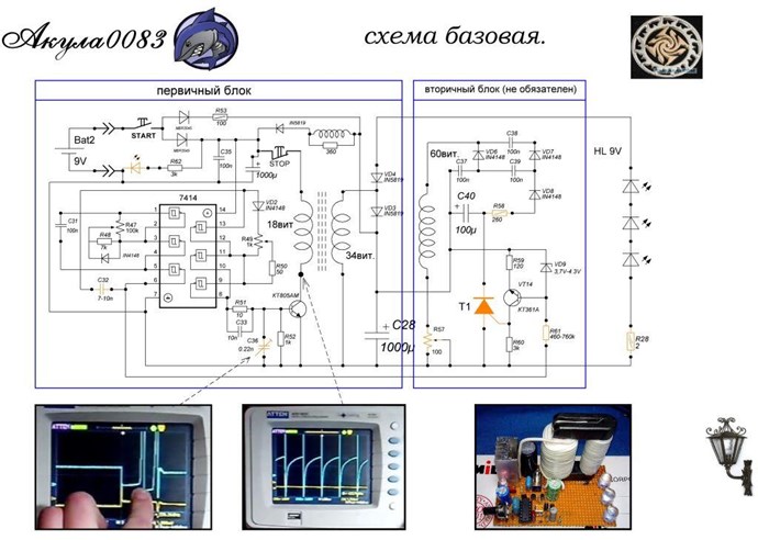
The schematic diagram that I used to create my PCB is shown below:

In the original diagram some of the component is not labeled, in order to make my PCB I need to add label to some of the component.
Below is the PCB that I made:

 Initially I solder every component exact as shown in the schematic diagram, and try to make it run, but it did not work correctly[LED did light up, but did not self run]. The 7141 inverter [labeled as U1 on the PCB] as signal generator, I found it is very sensitive to the value of C31 capacitor, and 100nF as shown in the circuit diagram is not going to make it generate a steady signal. I use a function generator to control the MOSFET or BJT instead, I will switch back to the on board signal generator when I make it working. I use the signal generator to control the BJT and go through may different frequency but did not self run.
After watching the video called "Our Flashlight" from Aboveunity and hyiq Research Channel, and after reading the two thread:
https://www.aboveunity.com/thread/akula-s-30-w-lantern-chris-s-replication/
https://www.aboveunity.com/thread/yoelmicro-s-ferro-magnetic-resonance/
I thought I need to go basic and to do some more experiment on ferroresonance.
The second experiment:
I created a circuit according to the schematic shown below:

Some detail is that, I did not use the IXDN619PI and it's related component as my signal generator, I use function generator instead, I did not use the IXFH220N06T3 MOSFET, I use IRF3205 instead. I use PC40 as the ferrite core material instead of 3C90. I did use EFD25 core and bobbin. I wrap 19 turn of 0.8mm diameter magnetic wire around the bobbin, and doing some experiment. Below is some of the result:


The ferroresonance start at 6kHz, with a duty cycle of 15%.
I latter use the same ferrite core as I used in the first experiment, and wrap around a multi strain soft wire of 0.5mm^2, with a turn ratio of 18 9, and use the same experimental setup as above, and I found it generate the same kind of waveform as above at 16kHz with a duty cycle of 25%, by just using the 18 turn primary, I think it should be at the ferroresonance. At the point of ferroresonance I use to connect some LED to the secondary, I found the more LED I connect the less current draw from the DC power supply, with some limit of how may LED you can connect, but the more LED you connect the less bright it became. The IRF2305 MOSFET datasheet said it have a rise time of 101ns, which is not at 20ns to 27ns range, maybe I should change to another faster switch MOSFET? I did get some good wave so I continued the experiment. [I forgot to take photo for this setup].
The second experiment on ferroresonance encourage me to go back to the first experiment to do some simple setup and see if I can make it into self run. [Note: Akula Latern number 4 seems using a different energy recovery process as shown by Our Flashlight video, the Akula circuit schematic shows the secondary have a 1000uF electrolyte capacitor, and it's positive terminal connect via diodes to another 1000uF electrolyte capacitor at the primary, I think the secondary charged up the cap, and send energy to another cap. In Our Flashlight video, the secondary is not connected to the primary and I think it use another energy recovery process not shown to us than the secondary coil feedback process use by Akula].
The third experiment:
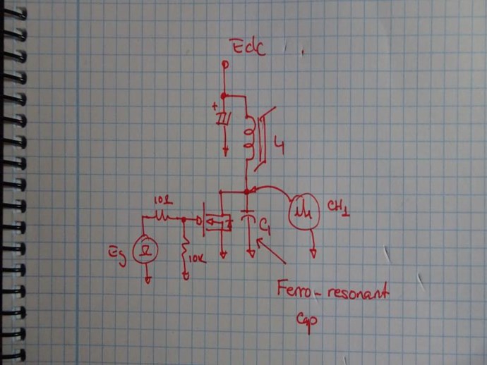
Below is the circuit schematic of my simple setup:

In the schematic diagram above I high light the component that I still use in the red circle, and I add the 4.7uF 400V cap from the second experiment. and I hope this could setup the ferroresonacne condition, and recover energy from the secondary to the cap that power the primary. I use a adjustable resistor to change the rise time, and use the function generator to control the gate.
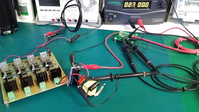
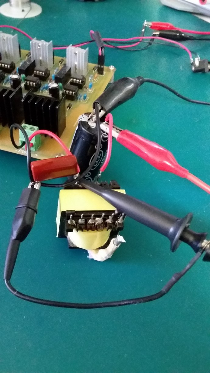
Below is the circuit setup:

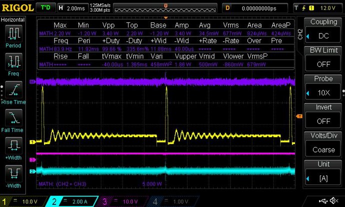
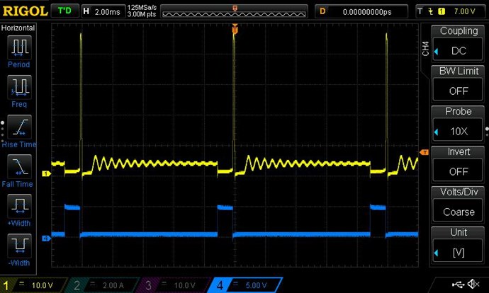
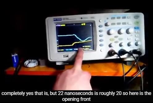
Below is the oscillscope image when the function generator is at 16kHz 25% duty cycle, the exact ferroresonance condition that I found during the second experiment.

The yellow trace is signal from the drain.
The blue trace is signal from the gate.
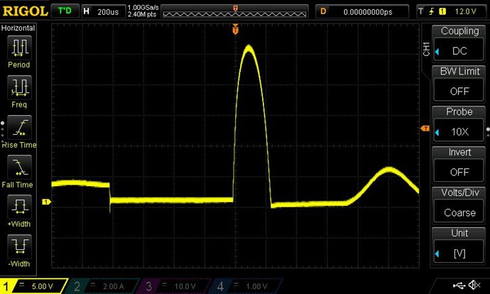
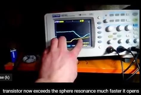
Now I do get some voltage recovery, but is not the same wave form as I saw before, and it need a lot of energy input from the DC power source, and the LED did not light up. Thus I change the frequency and duty cycle and I got the follow scope shot.

I thought this might get recover some energy, even through it still need a lot of energy input from the DC power source, and the LED did not light up. I try to disconnect from DC power supply and it did not self run.
I then disconnect the 4.7uF 400V cap from the circuit, and below is the circuit setup:

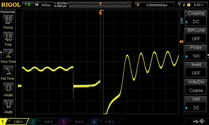
I tried to run at the ferroresonance frequency of 16kHz and 25% duty cycle, but the wavefrom changed a lot, and LED did not light up.

The wave form is the same if the second experiment disconnect from 4.7uF 400V cap. It generate a lot of oscillation after turn of the MOSFET, that oscillation should from the magnetic hysteresis oscillation because the magnetic energy have no where to go, and just oscillate back and forth.
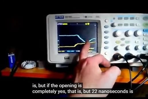
In order for it just stay in the first quadrant of magnetic hysteresis, I adjust both the frequency and duty cycle, and get to the frequency more than 500kHz,and duty cycle of near 50%, the LED did not light up, and did not self run below is the waveform:

Some thought on the experiment:
I think the circuit of Akula lanter number 4 on the internet is not correct, and change is needed, for example add a cap to the primary.
After the MOSFET turns off some the energy in the transformer need to go somewhere, or you can get a very fast oscillation.
Some questions:
What do you think I need to do to get the ferroresonacne in the third experiment, as I did in the secondary experiment?
What should I do to get the energy recovery?
Do you think Akula circuit and Our Flashlight video circuit have to different energy recovery process?
Do you think I did some some wrong or made a mistake in my experiment?[I am really looking forward to get some feedback!]
Most important thing of all:
Happy New Year!
MTKE