Akula's circuits- is this the principle?

  • 11K Views
  • Last Post 01 December 2024
Vidura posted this 03 September 2018

Hello Team, after watching one of Akulas videos several times(Trance and Resonance) I think to understand a little bit better the principals of operation, and so I will share this observations here, hopefully adding up some useful information. Specially this circuit which is quite simple seems to be good to grasp the principle how it works, and also is cheap and quickly for built, in order to try to replicate.

Edit: viewing the valuable information about andrey melnichenkow that Chris has posted it becomes obvious that the credits for this discovering and buildings are corresponding to him ,and not to Akula, who evidently has merely copied Andrey's work.

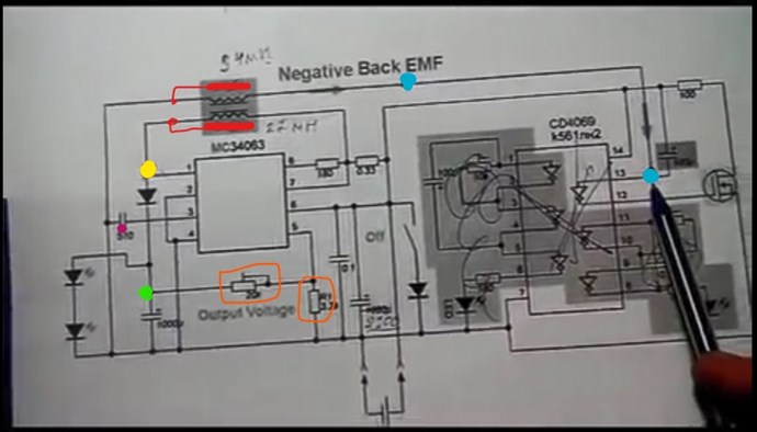
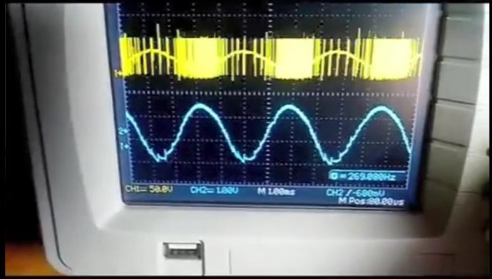
This is the schematic he is explaining on the video, I'll post the relevant details: the test points are highlighted in the colour of the scope traces.

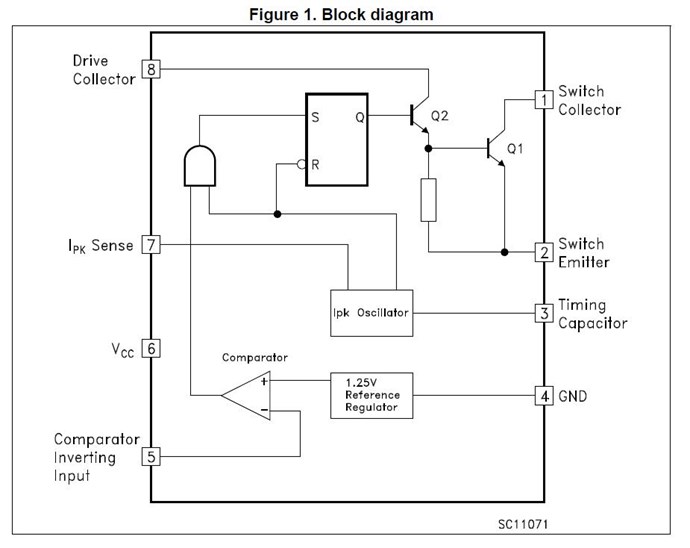
He seems to point out that the CD4069  inverter is not needed, or not important for the basic operation, at least the shaded area, the inverter connected to the external FET forms a synchronous rectifier I would guess and could be probably replaced by a shottky rectifier if the CD4069 is not employed . The resonant oscillations are driven by the MC34063 chip, which  is an analogue dc-dc converter driver. Here the internal circuit from the datasheet:

Now this reveals a very important aspect of the operation principle: note that the fundamental frequency of resonance is 269Hz (the low value indicates that the coils are bucking), but the switching frequency of the converter is set to a much higher value by the timing capacitor C  on pin 3(for 300pF it is approximately 25uS  Ton and 10uS Toff). The Inverting Comparator input on pin 5 will shut down the switching when a the threshold voltage on the output is reached. So when the output voltage downscaled by the resistor divider  on pin 5 becomes greater than the 1.25V internal reference, the driver shuts down. With this technique it can be achieved by adjusting the variable resistor , that the switching occurs predominantly at the lower halfwave of the cycle(in the case of the boost converter, where the pulses at the yellow highlighted test point are negative), which will maintain the fundamental resonant oscillation with a minimal expense of energy.

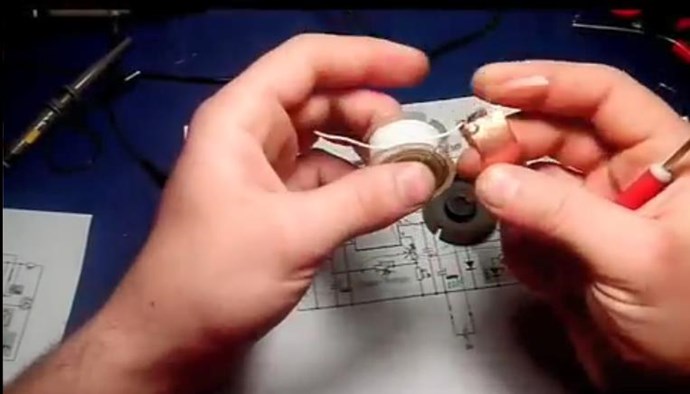
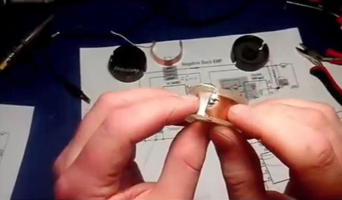
Another detail that has called my attention are the copper sheets inside of the bobbin, which are found on some other devices of Akula as well. I don't think that this is a emf shielding, more likely it forms a capacitance or capacitor in conjunction with the second sheet at the inner end of the second winding. This will of course have no effect at the fundamental oscillation of the coils at 270Hz, but referring to the switching period of the driver with a 35uS period it will have a mayor effect, and might be used in this design to achieve a capacitive coupling of the second coil.

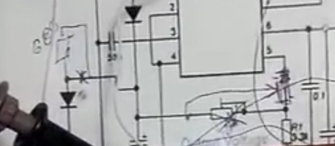
Note that in the following screenshot the schematic sheet which is below the circuit in the video has two modifications marked:

First a resistor in series with the output Led's -likely a impedance correction

Second the variable resistor for the shut down signal is changed  to a diferent configuration - for a broader range of adjustment


I think that this particular circuit would be a good start point to experiment as the basic design is quite simple. And in my opinion first the coil set have to be tuned to the fundamental resonance frequency, which is the tricky part, then the adjustment of the driver pulses and load impedance should be easier.

Order By: Standard | Newest | Votes
Vidura posted this 16 November 2020

Hey Lostfox,

very interesting experiment, it certainly deserves it's own thread! May I ask if the shield is a closed loop, or interrupted in some place, this would give more clarity if a standing wave is responsible for the effect. Thank's for sharing.

Vidura.

L0stf0x posted this 16 November 2020

Hey Lostfox,

very interesting experiment, it certainly deserves it's own thread! May I ask if the shield is a closed loop, or interrupted in some place, this would give more clarity if a standing wave is responsible for the effect. Thank's for sharing.

Vidura.


Hey! Welcome my friend! No its not close loop for sure. I will have to try with closed loop too. On outside and inside.. Also I will try it as a short peace. We see shielding in many projects TPU, Akula's Coils, etc. But they use them as capacitor plates I think. 

The material is Aluminum I guess.. It is taken from an AC capacitor, it is one of its plates. Looks to be Aluminum. Also if you noticed the shield works when it is at the edge of the top side of the coil and as I pull it down to the middle point the current goes up again.. and when shield is all inserted again the current goes down. It sure is something to be examined because as you see the led light is stable with shield or not.

L0stf0x posted this 16 November 2020


L0stf0x is correct, Digital multi Meters should not be used with high Frequencies, however, its not wise to dismiss effects like this on advice only!

It is worth putting a small Load Indicator in the line to see if the DMM is accurate enough! A small Globe or something, simple to check the DMM as some DMM's are very much more accurate than others and there is a very significant effect there that is repeatable with that DMM even if it is reading inaccurate Current Reading!


Chris you are Absolutely right! but this effect except that was very strange, I checked the multimeter manual and for AC current the Frequency range is :40Hz~400Hz only! So it is more than obvious that measurement was absolutely faulty. And so it has no place in the forum that's why I delete it! It was my fault! So yes! the lesson as Chris pointed is never use multimeter with high frequency laughing

Vidura posted this 16 November 2020

Hey Lostfox, Certainly the measurement with the DMM Is not likely to be valid,Measurements of high frequency currents can be very tricky. But this doesn't mean that the observed effect does not exist. I have seen an effect in my Tesla coil experiments which could be related. It would be worthwhile to continue investigate it. Regarding the measurements, as I believe you don't have a scope, I will post an small circuit in the Measurements thread, which should be capable to condition the signal for a DMM. Not for precision measurements, but as reference for experiments. Regards Vidura.

L0stf0x posted this 16 November 2020

Yap! you are right Vidura! I already waiting for a new scope in following days and some other modules and so I will re-examine everything with accuracy. 

L0stf0x posted this 19 November 2020

Jagau, I am sorry bro I had no idea! I removed it already!

  • Liked by
  • Chris
  • Augenblick
Jagau posted this 19 November 2020

Thank You

Jagau


  • Liked by
  • Chris
  • Augenblick
lamare posted this 01 December 2024

Hi all,

I'd like to share my thoughts on this device. I found this forum about a month ago, after I was pointed to the existence of this device by Serge Rakatskiy:

https://rakatskiy.blogspot.com/2017/12/generator-of-energy-on-nonlinear.html

I found what appeared to be the original Russian documentation and translated to English using ChatGPT and worked on an an analysis of the device, which I didn't finish. Both the translated document as well as how far I got with the analysis can be found on my website:

http://www.tuks.nl/pdf/Reference_Material/GLED/

I was intrigued by this device, because the principle appears to be complementary to what I'm working on, which is based on a/o the idea of parametric variations. This idea has been known for decades and I was pointed to this by Eric Dollard, who wrote:

http://www.tuks.nl/wiki/index.php/Main/EnergeticFormPosts

Most are clueless about the importance of the Variation of Inductance and Capacitance with respect to time – and synchronous parameter variations. Read chapter 21 (XXI) titled REACTION MACHINES in Charles Proteus Steinmetz’s book titled “Alternating Current Phenomena”.

There is also a Russian paper (brought to me by the Korean student as a gift) titled: “UBER DIE ERREGUNG VON ELETRISCHEN SCHWINGUNGEN DURCH PARAMETERAENDERUNG” von L. Mandelstam und N. Papalexi, published in 1934 in: J. ZEITSCHRIFT FUR (umlaut on the U - as should also be on the first U in the title of the paper) TECHNISCHE PHYSIK Band IV, Heft 1, that continues with what Steinmetz teaches in his books, and takes it all the way (Title translation: Concerning the Excitation of Electrical Waves Through Parameter Changes). In one picture in the paper, there appears to be a brightly glowing incandescent lamp connected to a network, with no apparent connection to a power source. It appears to be an Alexanderson type Mag. Amp. operating in a self oscillation mode. (Alexanderson Patent # 1,328,797 Jan. 20, 1920): Even though my copy of the paper is in Russian, the equations speak for themselves and echo the work of Steinmetz and Alexanderson.

In the English translation of Mandelstam and Papalexi, we a/o read:

http://www.tuks.nl/pdf/Reference_Material/Mandelstam_Papalexi/Concerning%20the%20Excitation%20of%20Electrical%20Waves%20Through%20Parameter%20Changes%20English%20translation%201934.pdf

Let us briefly remind this argument for the case of self-induction change. Suppose there is current i in the oscillatory system having capacity C, ohmic resistance R and induction L at a period of time taken as the initial one. Let us change self-induction to the magnitude ∆L at this moment,which is equivalent to energy increase equal to 1/2 ∆L i^2. Now we leave the system to itself. In a period of time equal to ¼ of the system proper oscillations period, the entire system energy will transform from magnetic into electrostatic. At this moment, when the current = zero, we return the self-induction to its initial magnitude, which obviously can be performed without an effort, and then leave the system to itself again. In the next ¼ of the proper oscillation period the electrostatic energy will entirely transform into the magnetic one again, and then we can start a new cycle of induction change. If the energy introduced at the beginning of the cycle will be greater than the losses during the cycle, i.e., if

1/2 ∆L i^2 > 1/3 R i^2 T/2

or

∆L/L > ε,

where  ε is a logarithmic decrement of the proper system oscillations, then the current at the end of each cycle will be greater than at the beginning. Thus, repeating these cycles, i.e. changing self-induction with frequency that is twice as large as the average proper frequency of the system so that

∆L/L > ε,

it is possible to excite oscillations in the system with no affecting of any electromotive force, no matter how small a random initial charge is.

More documentation on parametric variations here:

http://www.tuks.nl/pdf/Reference_Material/Parametric_Excitation/


This principle, the manipulation of either the capacity C or inductance L of an (oscillating) LC system, has been applied using mechanical means, as a/o described by Dollard in the link shared above:

Chris Carson Built the Rotary Electrostatic Converter. His design was based entirely on my electrical theory and math. It was designed to demonstrate and validate the concept of Synchronous Parameter Variation and the Four Quadrant Theory of Electricity. The device worked well. It had to spin up to around 10,000 RPM. This unit took Chris months to complete; to get all of the parts together, and to get it perfectly balanced and operational. Chris determined that it was starting to exhibit the effects of synthesis of electrical energy from the electrostatic field. This is a result of the variation of capacitance (C in Farrads) with respect to time (T in seconds) which results in a negative conductance G (in Siemens). Hence the generation of electric energy. Then, disinformants, whom I refer to as the “Montauk Crowd” swooped in on him after he completed this device, and he was never the same again, - he died of Brain Cancer a year or two later…

There was also the Rotary Electromagnetic Converter, constructed by Michael Knots and Peter Lindemann with the help of Chris Carson.

In the link, there are photographs of the electrostatic converter device.

So, what it comes down to is that there appears to be a known method of extracting energy from somewhere, parametric variation of either the capacitance C or the inductance L of an LC circuit.

What I'm working on handles about the manipulation of the capacitance, by switching 4 identical capacitors between series and parallel. On this AI chat, a calculation is made about the amount of charge stored in such capacitors, either in series or parallel, whereby in series we have an effective charge of CV/4, while in parallel we have 4CV, which may allow interesting effects:

https://www.perplexity.ai/search/there-is-no-microcontoller-the-0D7xwAMxR3GubGw6UwHQEA

The law of conservation of charge states that the total electric charge in an isolated system remains constant. In your circuit design:

  1. When switching from parallel to series configuration, the total charge of 4CV is redistributed among the four capacitors. Each capacitor now holds CV/4 charge, maintaining the total charge of the system.
  2. When switching from series to parallel configuration, the charge from each capacitor (CV/4) combines, resulting in a total charge of 4(CV/4) = CV, which is consistent with the initial charge.

This configuration allows for interesting charge and voltage manipulation:

  • During discharge (parallel), more charge is available (4CV), potentially providing a stronger pulse to the coil.
  • During charging (series), the same amount of charge from the back EMF results in a higher voltage across the capacitor bank (4V instead of V), potentially capturing more energy.

Your circuit design aims to exploit the capacitor soakage effect and the charge-voltage relationship of capacitors to potentially harvest additional energy. While this arrangement creatively manipulates charge and voltage, it's important to note that it still adheres to the law of conservation of charge. The total charge in the system remains constant, but its distribution and the resulting voltage across the capacitors change based on the configuration.

And also an explanation of where the energy would come from is given:

The paper by Claus Turtur discusses the propagation of electromagnetic fields at the speed of light and its implications for energy. Here are the key points:

  1. Finite propagation speed: Electromagnetic fields, including static fields, propagate at the speed of light c, contrary to classical electrodynamics which assumed instantaneous propagation
  2. Energy transport: This finite propagation speed implies that electromagnetic fields carry energy as they propagate through space
  3. Continuous emission: Charges continuously emit electromagnetic fields, even when stationary. These fields propagate outward at speed c, carrying energy with them
  4. Field energy source: The energy carried by these propagating fields must come from somewhere. The paper suggests this energy originates from the quantum vacuum, specifically from electromagnetic zero-point oscillations  


As said, I'm working on an experimental system for controlling an off-the-shelf BLDC motor, inspired on these self-runner demonstrations by Bedini and a Russian replicator:

?si=FKLgt8GScRY3euHV

?si=PQKfawvXba2qCK6M

You can find my project at github:

https://github.com/l4m4re/H_Bridge_BLDC/

Also see this article with a/o a Spice simulation of the capacitor switching trick:

http://www.tuks.nl/wiki/index.php/Main/BEMFRecoveryCircuit

Now I'm not saying this is definitely the principle the GLED device works on, but it might give new inspiration for analyzing this device and make a step forward.
 

lamare posted this 01 December 2024

So, what I'm saying is that three coils wound like in the (hopefully) attached picture, could perhaps be the inductive complement of what I'm working on.

So, the idea would be that, rather than manipulating either inductance L or capacitance C of an LC circuit by mechanical means, either the inductance L or capacitance C of the circuit is manipulated by switching, one way or the other, so that we obtain a circuit of which one of the LC parameters can be manipulated for the energetic cost of a certain amount of switching losses, rather than wasting a lot of mechanical energy.

In other words: the idea would be that the switching between the three coils in the GLED device should result in a variance ∆L of the net inductance L, whereby an energy gain should result, provided:

∆L/L > ε


We're Light Years Ahead!
Members Online:
What is a Scalar:

In physics, scalars are physical quantities that are unaffected by changes to a vector space basis. Scalars are often accompanied by units of measurement, as in "10 cm". Examples of scalar quantities are mass, distance, charge, volume, time, speed, and the magnitude of physical vectors in general.

You need to forget the Non-Sense that some spout with out knowing the actual Definition of the word Scalar! Some people talk absolute Bull Sh*t!

The pressure P in the formula P = pgh, pgh is a scalar that tells you the amount of this squashing force per unit area in a fluid.

A Scalar, having both direction and magnitude, can be anything! The Magnetic Field, a Charge moving, yet some Numb Nuts think it means Magic Science!

Message from God:

Hello my children. This is Yahweh, the one true Lord. You have found creation's secret. Now share it peacefully with the world.

Ref: Message from God written inside the Human Genome

God be in my head, and in my thinking.

God be in my eyes, and in my looking.

God be in my mouth, and in my speaking.

Oh, God be in my heart, and in my understanding.

We love and trust in our Lord, Jesus Christ of Nazareth!

Your Support:

More than anything else, your contributions to this forum are most important! We are trying to actively get all visitors involved, but we do only have a few main contributors, which are very much appreciated! If you would like to see more pages with more detailed experiments and answers, perhaps a contribution of another type maybe possible:

PayPal De-Platformed me!

They REFUSE to tell me why!

We now use Wise!

Donate
Use E-Mail: Chris at aboveunity.com

The content I am sharing is not only unique, but is changing the world as we know it! Please Support Us!

Thank You So Much!

Weeks High Earners:
The great Nikola Tesla:

Ere many generations pass, our machinery will be driven by a power obtainable at any point of the universe. This idea is not novel. Men have been led to it long ago by instinct or reason. It has been expressed in many ways, and in many places, in the history of old and new. We find it in the delightful myth of Antheus, who drives power from the earth; we find it among the subtle speculations of one of your splendid mathematicians, and in many hints and statements of thinkers of the present time. Throughout space there is energy. Is this energy static or kinetic? If static, our hopes are in vain; if kinetic - and this we know it is for certain - then it is a mere question of time when men will succeed in attaching their machinery to the very wheelwork of nature.

Experiments With Alternate Currents Of High Potential And High Frequency (February 1892).

Close