Brian's Eternal Flashlight Replication

  • 5.8K Views
  • Last Post 25 December 2022
Brian posted this 16 October 2021

HI Team

I arrived at this forum with the goal of learning how to make a Eternal Flashlight, but found a wealth of knowledge far beyond expectation. After much reading, watching, coils and experimenting quietly, its is now time to see if I can offer something to this effort. 

I decided to start with a "Lariman" build due to its circuit simplicity but still with the necessary components to understand the coils and what is required to tune them to the circuit. I have ordered circuit boards based on the above design and have a number of spare which I am happy to post to any one willing to commit to building and posting their progress.

Lariman Circuit Boards

So I will build one up and wind some coils and post progress soon.

Order By: Standard | Newest | Votes
Jagau posted this 06 April 2022

Hi Brian
A site that I like, you will find answers to your questions on how to find resonance on LC circuit, this guy explains much better than me.


Jagau

Chris posted this 08 April 2022

My Friends,

I have used a BUZ11 Mosfet and that worked fine as did the 3055, but trial and error with Coils and the Circuit made specifically for predesigned Coils is not what we have done here, we are attempting to guess the Coils Design around the Circuit, not an ideal option as this is much more work!

Experiments here on this website, aboveunity.com, sheds more light on what is supposed to occur here.

Brian, you had the effects in the Coils, you just need to focus on those effects and see what is actually occurring there, and work out how to improve this effect, after all, this is Asymmetrical Electromagnetic Induction.

More work on this effect will yield results!

Best Wishes,

   Chris

Jagau posted this 03 May 2022

Hello Brian
I don't know if it's going well for you, give us some news about your experiences.

I would like if you have the time to make an etlernal flasher ?

. I have one here that has been working since last year, with only one LED though, and recharges itself with the energy that surrounds us and does not need to be charged at the start and works without batteries.
Jagau

Brian posted this 05 May 2022

Hi Jagau

I am certainly interested to take up your offer to make the eternal flasher.

I have many projects on the go that are almost there and or demonstrate the effect needed, it would be great to finally achieve a small self running success.

I only just managed to recover from a old UPS a suitably sized transformer to use its core for your Melnichenko's Effect experiment. as well as waiting for IGBT delivery.

I do apologize for not updating progress on this eternal flashlight experiment, the reason being I have not been able to advance the knowledge for success as yet. Many have commented on the fickle nature of this design and felt that working with his later designs that can deliver a more practical power level would both help advance my understanding and be more productive in terms of out come.

I look forward to the construction details of your eternal flasher.

Kind Regards

Brian

Jagau posted this 05 May 2022

Hi Brian
yes Melnicehnko's experience is far from over, I have other things still developed that I will publish soon.
For the eternal blinker here it is:
The circuit presented here is a replica of the Akula lamp but with a single LED that flashes eternally, harvesting the energy that surrounds us.
It is based on the principle of Akula's first circuit:

2


You will recognize the SCR in 2 BJTs, namely T1 and T3 as well as a trigger T2 which recharges the capacitor C1.
I built this circuit with a modification of the T2 trigger circuit which flashes an LED by harvesting the energy around us. The more energy there is around you, the faster the LED will flash.
The circuit :

mon ckt

There's no battery, only a capacitor that charges as you harvest ambient energy. There are two grounds in this circuit, one on bare copper with a ground rod outside planted in the ground and another ground which can be either your body or the metal of your work lamp as in the following short video. I built two, one on bredboard and one on a fixed plate.

This circuit has been in operation since November 2021

Have fun
Jagau

Brian posted this 07 May 2022

Hey Jagau

Had a little bit of time this morning so knocked up your eternal flasher experiment. 

The earth connection used is house mains power ground, while as you can see I make a pretty decent aerial😄

 Regards

Brian


Jagau posted this 07 May 2022

Great Brian
You see we have to indulge ourselves from time to time, it's like a little reward and it works.
I already have a very small modification made with a little more tension, I'll tell you about it.
Jagau

Jagau posted this 07 May 2022

Brian thread

To stay in the interesting subject of your thread Brian, when you built this coil similar to that of Akula

  I think you had some problems with the start of the oscillator.
Therefore, a more in-depth study of the circuit is necessary. The last circuit you built on the collection of radiation around us is a good basis for understanding what will follow and you will notice that the circuits are similar in their operation.
If I bring this circuit comparison:
Photo
As much as the circuit of Akula in comparison to that of the SCR with 2 BJT it is easy to understand how the gate of the SCR is triggered, see the yellow line on the two circuit comparisons is the one that interests us so with a negative pulse the scr is active. Before continuing I stop it for the moment so that the two circuits can be digested and understood and even experienced.
Jagau

Jagau posted this 07 May 2022


Hi Brian

To stay in the interesting subject of your thread Brian, when you built this coil similar to that of Akula


brian xfo


  I think you had some problems with the start of the oscillator.
Therefore, a more in-depth study of the circuit is necessary. The last circuit you built on the collection of radiation around us is a good basis for understanding what will follow and you will notice that the circuits are similar in their operation.
If I bring this circuit comparison:

scr de bjt


As much as the circuit of Akula in comparison to that of the SCR with 2 BJT it is easy to understand how the gate of the SCR is triggered, see the yellow line on the two circuit comparisons is the one that interests us so with a negative pulse the scr is active. Before continuing I stop it for the moment so that the two circuits can be digested and understood and even experienced.
Jagau

Brian posted this 08 May 2022

Thanks Jagau

I did go back to that experiment several weeks back. I felt that stated 3v 10ma start supply was not enough to produce the trigger on L3 to begin oscillation, so I upped the voltage and played with R1 value but couldn't get a significant pulse. Maybe L3 needs more turns.

I would be very interested if you have a working circuit for this. I really do like the coil design.

Kind Regards

Brian

Jagau posted this 08 May 2022


Hi Brian

For this I would need the number of turns, of each coil and their iductance?

Very low inductance mean megahertz range of operation.
Normally with the intrinsic capacitance of each coil this is enough with the SRO

but for some we must place a capacitor in them

Jagau

Brian posted this 09 May 2022

Hi Jagau

Details of the my circuit.

L1 4 turns - 8uH, L2 98 turns - 13uH, L3 98 turns - 19 uH,

T1 TIP41 (akula video shows a transistor in a TO-3 case)

T2 & T3 - 2N3906

D1 & D2 - 1N4004

What are your recommendations Jagau?


Kind regards

Brian

Jagau posted this 09 May 2022

Ok I see
You make it exactly like Akula's schematic.
In other words this one in real.

As you can see it is not as simple as in its schematic and more if you count the number of transistors there are 4 and a greater number of conductors output. We don't know yet if it's an air core or if internal are orthogonal winding.
I will review your request and get back to you with suggestions.
Jagau

Jagau posted this 09 May 2022

Hi Brian
Instead of 200pf on the SRO, try

between 1 and 2 microfarad you should have a good oscillation, as you have very low inductance

Jagau

Brian posted this 10 May 2022

Yes Jagau, I copied his circuit. It is really hard to see exactly the components and numbers from the video I had so just had a stab at what was provided to see the results.

I will adjust the SRO caps and test.

Kind Regards

Brian


Chris posted this 10 May 2022

Hey Guys,

Pardon my interruption, do you guys mean: Silicon Rich Oxide (SRO) Capacitor?

I think instead of assuming and taking a chance on meaning, I should ask and be proactive in the pursuit of understanding. 😏

Thanks Guys, appreciate your pursuit and Due Diligence!

Best Wishes,

   Chris

  • Liked by
  • Augenblick
Jagau posted this 10 May 2022

Hi Chris

SRO is for self running oscillator.

have a nice day

Jagau

  • Liked by
  • Chris
  • Augenblick
Brian posted this 11 May 2022

Hey Jagau

Using your standard SRO design connected to L2 and taking .2uf steps from .2uf to 2.2uf the result is bursts of oscillation of the frequency 300 to 390kHz with L3 loaded and up to 1MHz with L3 open

The SRO circuit does not maintain a constant oscillation. But with 3V supply the bursts are 18V so could charge sufficiently the C1 cap in Akula circuit 

To your knowledge has there been a replication of the Akula 1W Lantern circuit?

2 

It has a beautiful simplicity, but I cannot make out from the video the detail to replicate.

Kind Regards

Brian 

Jagau posted this 11 May 2022


To answer your question honestly, I haven't seen any real replication anywhere on the planet.

The only replication that comes close is the eternal blinker you did, that's a good start.

To return to the circuit that Akula proposes, the subtle difference that you have surely noticed is that it does not use any capacitor in its oscillator, only the capacitive effect between two coils, we have reached the same point in our research Brian, he only remains this effect which has not yet been found.


jagau

Brian posted this 22 May 2022

Hi Team

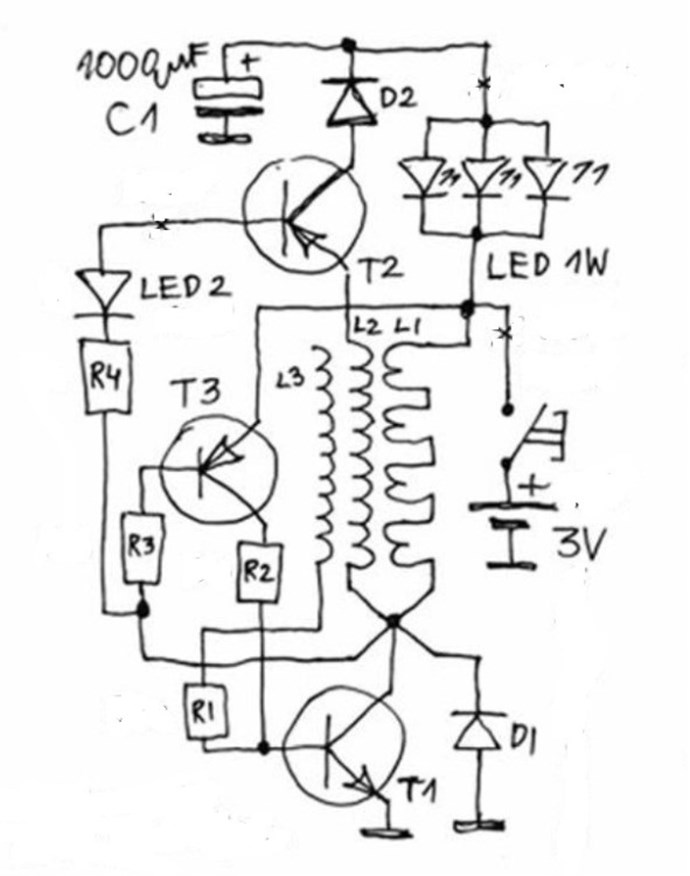
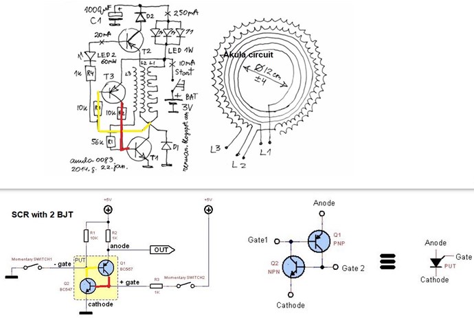
I have been experimenting with a simplified design using the coils to switch the BJT and combined this with POC coils.

My idea was to have a "semi" self tuning pulse similar to Jagau's SRO and a very basic implementation of Melnichenko circuit above.

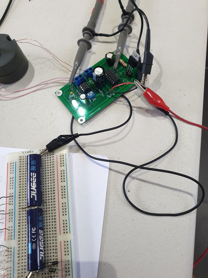
Here is what I have started with, very simple, but some very interesting results. Will run on as little as 0.5volts while still lighting 18 LEDs. 

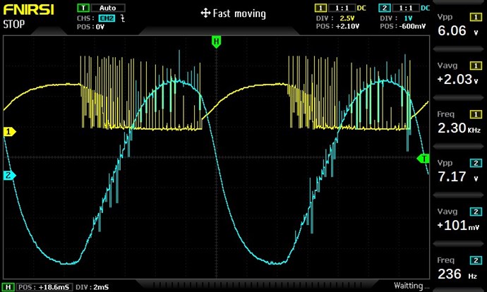
In the picture below the Blue trace is accross the BJT and the Yellow the current through a 1ohm resistor on the CCW coil. Nice sawtooth wave. 

As you can see I am using 1Volt supply which is drawing 70mA and lighting brightly 18 LEDs. Surprisingly the circuit draw with only 2 LEDs is still about the same.

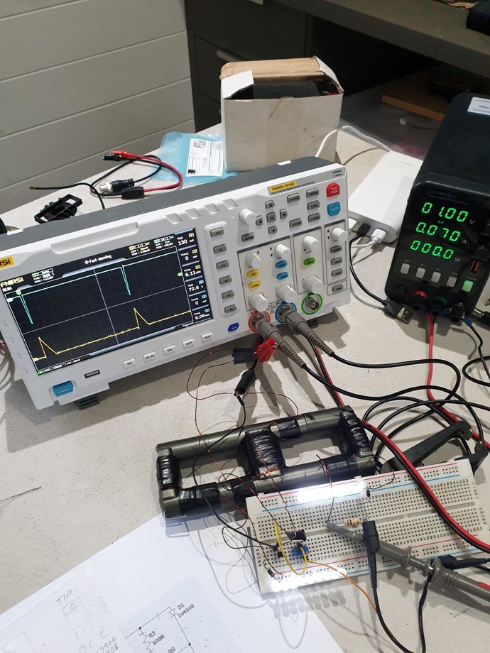
The variable resistor is a 10 turn to allow for fine tuning. Surprisingly it adjusts for a very wide frequency and influences voltage peak and current draw as you would expect. 

I have much to explore yet as I have burnt out several BJTs, VRs and over 20 LEDs as I tune to a frequency slightly below where I am at here. As I approach this point the cores vibrate loudly and there is ringing pattern across the BJT then puff. I solved this by limiting the supply current, but have some investigating to do here.

Raising the supply voltage increases the frequency and the current in the system. Which extends the sawtooth wave approaching more the ideal.

There are many areas to explore here. 

I encourage others to give this very simple build a go.

Kind Regards

Brian


Jagau posted this 22 May 2022

Hi Brian
It's a great and rewarding experience.
To avoid burning other LEDs you can add a load resistor in series with your LEDs, this will limit the current flowing through the LEDs. Here a small calculator:

https://www.allaboutcircuits.com/tools/led-resistor-calculator/

Cheer

Jagau

Brian posted this 16 December 2022

Hi Team

Been a while since I updated this post. Thanks to some encouragement by Chris I thought I would pull this project out and take another look at it. Looking back through this post I see it has been about a year. Wow how time gets away.

I was paying a bit more attention this time to the tuning with the 20K pot and noticed that it may be worth using a 10 turn pot here it seemed to be easy to skip past some sweet spots. Seems my scope is getting interference between the channels. Might be time for a better one?


I tried further tuning via the timing cap on pin3 of the MC34063, but the effects were minimal.

I welcome suggestions for directions to make this self run.

Many Thanks

Brian

Chris posted this 17 December 2022

Hey Brian,

This is great work!


Its hard work getting the wave, we have to tune the coils to the Circuit, and not the Circuit to the Coils, its a fiddly task!

Don't give up mate, you're getting closer!

Best Wishes,

   Chris

Brian posted this 18 December 2022

Thanks Chris

Are you able to be a little more specific when you say

 we have to tune the coils to the Circuit, and not the Circuit to the Coils, its a fiddly task!

I am not sure if I should be 

  1. Adding or removing turns on primary or secondary
  2. Adjusting copper strips to adjust capacitance
  3. Changing the timing cap
  4. Something else I may have overlooked.

I have been going around in circles with this for some time now not really sure with what to tune to get the result?

Kind Regards

Brian

  • Liked by
  • Chris
  • Augenblick
Chris posted this 18 December 2022

Hey Brian,

If I were you, I would put this particular experiment aside for a little while, but concentrate on the effect!

I have shown the very same effect here: Non-Inductive Coil Experiment

The Effect is where you will learn the most. The Effect is Asymmetrical Regauging

Best Wishes,

   Chris

  • Liked by
  • Augenblick
  • ISLab
Brian posted this 20 December 2022

Noted - Thanks Chris

  • Liked by
  • Chris
  • Augenblick
donovan posted this 25 December 2022

Hi,

Anyone catch the Pot Core number?

I have been a troubleshooter around electronics enough to know to question everything.....what if the L1/L2 coils were reversed......the same approximate length of wire (23 arms, and 26 arms) for each being about the same.....the inner core would result in more turns than the outer core which would result in more inductance......I need to do some math.


Donovan

We're Light Years Ahead!
Members Online:

No one online at the moment


What is a Scalar:

In physics, scalars are physical quantities that are unaffected by changes to a vector space basis. Scalars are often accompanied by units of measurement, as in "10 cm". Examples of scalar quantities are mass, distance, charge, volume, time, speed, and the magnitude of physical vectors in general.

You need to forget the Non-Sense that some spout with out knowing the actual Definition of the word Scalar! Some people talk absolute Bull Sh*t!

The pressure P in the formula P = pgh, pgh is a scalar that tells you the amount of this squashing force per unit area in a fluid.

A Scalar, having both direction and magnitude, can be anything! The Magnetic Field, a Charge moving, yet some Numb Nuts think it means Magic Science!

Message from God:

Hello my children. This is Yahweh, the one true Lord. You have found creation's secret. Now share it peacefully with the world.

Ref: Message from God written inside the Human Genome

God be in my head, and in my thinking.

God be in my eyes, and in my looking.

God be in my mouth, and in my speaking.

Oh, God be in my heart, and in my understanding.

Your Support:

More than anything else, your contributions to this forum are most important! We are trying to actively get all visitors involved, but we do only have a few main contributors, which are very much appreciated! If you would like to see more pages with more detailed experiments and answers, perhaps a contribution of another type maybe possible:

PayPal De-Platformed me!

They REFUSE to tell me why!

We now use Wise!

Donate
Use E-Mail: Chris at aboveunity.com

The content I am sharing is not only unique, but is changing the world as we know it! Please Support Us!

Thank You So Much!

Weeks High Earners:
The great Nikola Tesla:

Ere many generations pass, our machinery will be driven by a power obtainable at any point of the universe. This idea is not novel. Men have been led to it long ago by instinct or reason. It has been expressed in many ways, and in many places, in the history of old and new. We find it in the delightful myth of Antheus, who drives power from the earth; we find it among the subtle speculations of one of your splendid mathematicians, and in many hints and statements of thinkers of the present time. Throughout space there is energy. Is this energy static or kinetic? If static, our hopes are in vain; if kinetic - and this we know it is for certain - then it is a mere question of time when men will succeed in attaching their machinery to the very wheelwork of nature.

Experiments With Alternate Currents Of High Potential And High Frequency (February 1892).

Close