Brian's Eternal Flashlight Replication

  • 5.8K Views
  • Last Post 25 December 2022
Brian posted this 16 October 2021

HI Team

I arrived at this forum with the goal of learning how to make a Eternal Flashlight, but found a wealth of knowledge far beyond expectation. After much reading, watching, coils and experimenting quietly, its is now time to see if I can offer something to this effort. 

I decided to start with a "Lariman" build due to its circuit simplicity but still with the necessary components to understand the coils and what is required to tune them to the circuit. I have ordered circuit boards based on the above design and have a number of spare which I am happy to post to any one willing to commit to building and posting their progress.

Lariman Circuit Boards

So I will build one up and wind some coils and post progress soon.

Order By: Standard | Newest | Votes
Brian posted this 09 November 2021

Hey Team

Thought it might be time for a update.

Over the past several days the experiments have followed the line of tuning L2 to a length proportional to L1

I measured the length of L1 including all tails to get the total aerial length (so to speak) and treated L1 as 1/4 wavelength. L1 is about 26mH. As a note the inductance of L1 changes slightly with different windings on L2 (open circuit). Also copper strips are connected either side of L1 and are located on the very inner and very outer of the windings on a 45mm Potcore. Supply voltage 3V.

The measurements of each experiment are as follows:

L1 24.2mH (1/4 wave) / L2 302mH (4/4 wave)

L1 26.8mH (1/4 wave) / L2 187.4mH (3/4 wave)

L1 23mH (1/4 wave) / L2 71mH (1/2 wave)

Unfortunately for whatever reason the pic of the full wave L2 did not save, but the result was unsuitable.

The Above is L2 3/4 wavelength wire

The above is L2 1/2 wavelength wire. (the bursts of resonance are more tightly packed than either 4/4 or 3/4 wavelength winding experiments - I think this might also be showing a limitation of my scope when storing snap shots)

Also to note my circuit is using a 330pF timing cap currently as I did not have a 510pF and I note that several other circuits using the MC34063 are using this value. (a 510pF cap is on its way). I also used a variable air gap cap to explore the effect of changing the 510pF timing cap from 330pF to 840pF. There were no improvements to note with the variance, but this may be down to length of wires and the air gap cap itself.

My feeling is the 1/4 wave - 1/2 wave L1 - L2 relationship was working better on this core as additionally I could drop the input voltage to 2.2 and still brightly light the LEDS and measure 2.8V at the 2200uF cap.

In conclusion I feel that finding the correct L1 inductance and winding L2 to double L1's wire length may be a step in the right direction. Finding the sweet spot value for L1 is the next task.

Chris I am interested to know the answer to your question "Can anyone point out the issues I have with my Waveform?"

Kind Regards

Brian


Brian posted this 10 November 2021

A quick update.

Rewound L1 to 27mH and remeasured length.

Rewound L2 to double L1 length including tails - 98.1mH

Have lost those tightly packed resonant areas on the waveform but have a increase in voltage on CN1 and CN3

I think I will wait until I have the 510pF timing cap to install to ensure the circuit is an exact replica.

Chris posted this 10 November 2021

Hey Brian,

You said:

Rewound L2 to double L1 length


This gives a Turns Ratio of: 1 : 2 Right?


I calculated for you:

So, turns ratio, are 1 : 1.414


Which can be factored, and worked out using the Greatest Common Factor, for complete turns. Which are?

Anyone?

I have said, attention to detail, 5 more minutes focusing on Theory can save Hours on the bench Winding Coils. Failure comes from Incomplete understanding, mostly. There are inaccuracies in my post Here, but I do give you a great deal information! That's all I can do to try and help!

Best Wishes,

   Chris

Brian posted this 10 November 2021

Thanks for the clarification - yes I agree I did not understand your instructions

So, turns ratio, are 1 : 1.414, so we could say, 1 / 1.414 = 0.707 and 1 - 0.707 = 0.29278, so not quite our 1/4 wavelength... Which is 0.25. Confused?

I mistook this calculation as proof of a 1/4 wave to fullwave relationship of L1 / L2 lengths.

Thankyou for that clarity.

Kind regards

Brian


Jagau posted this 10 November 2021

Hi Brian
For the lamp I worked a lot with a first Shark circuit. It is easier to understand and experience with . I have had great success with this arrangement and even today I am experimenting with this circuit which is composed of two BJTs in SCR mode and a third PNP transistor which resets C1 when the switching comes its turn.

Here is shark youtube:

Jagau

Brian posted this 11 November 2021

HI Team

Sorry for that little side diversion. On a positive note I have shown the results of the relationship of L1 / L2 with half, three quarter and full wave windings. 

So back to where I left off several days ago.

My best result was a L1 29.9mH - L2 59.4mH which via the calculator works out as 1 : 1.41, very close to what Chris calculated above.

I have adjusted now to as close as I can get to to 27/54  L1/L2 proposed values.

Below is L1 27.1mH - L2 54.2mH

It seems from these results there is better resonance when L1 is higher.

My question now is - with this circuit how do we arrive at what we should aim L1 and L2 to be? If we are relying on the copper strips to create the capacitance for the resonant LC circuit at L1, I am not sure how to measure this, as if I put my meter on it I get a negative result on the meter??? Which makes no sense to me.

Is there a solution to how to calculate the inductance of L1 for this circuit.

It seems from this if L2 is wound with 1 : 1.414 turns ratio then we are in the ball park.

Kind Regards

Brian


Chris posted this 11 November 2021

Nice work and Thank You for Sharing Brian!

Its not hard to see you're heading in the right direction! IC Current is something to look at, did you look at the links to the calculators I posted Here? Of course if the Current Draw is too much, the Circuit wont self run! A factor to look at!

Best Wishes,

   Chris

Brian posted this 12 November 2021

Hey Chris in regards to current draw seems minimizing Q1 on time seems important here. I don't understand or observe the pumping effect of this part of the circuit and it does not seem to have a positive effect with my tests. If I take Q1 out the current drops yet the wave forms remain the same. Made me think I had something wrong with this part of the circuit yet I can see Q1 switch with a probe on the Drain. I can save 20mA without Q1 and CD4069.

I understand that there is a purpose for this even though I have not been able to observer it.

In regards to progress with the coils, I note my best results with L1 37.1mH - L2 74.9mH which supports the 1:1.414 turns relationship. Current draw of the circuit at 2.2V was 22mA or (10mA with Q1 out)

In general lower frequencies seem to have lower current draw requirements which also result in lower voltages differentials at CN1 and CN3 which seem to match the calculators prediction for current if Vin and Vout are less different.

L1 37.1mH - L2 74.9mH above

Kind regards

Brian

Brian posted this 14 November 2021

Hi Team

Spent some more time on this project slowly increasing the L1 inductance while maintaining the L2 1:1.414 ratio.

Unfortunately I have not been able to improve performance and lower current draw any further. Current L1/L2 IS 41mH/82.1mH.

A consistent observation is that less current is drawn if tuned to a lower frequency. Also taking Q1 out of its socket has no effect on CN1, CN3 waveforms but reduces current draw about 20mA.

There is something I am missing regarding bringing in the function of Q1 but at this stage I am not sure how to activate it.

My last increase to 41mH / 82.1mH seems to support that increases further is not an advantage. Below are both the same core with differnet tuning to demonstrate the lower current at lower frequencies.

188mA draw at 124Hz

58mA draw at 57.5Hz

Testing indicates that L1 around 29mH has to date produced the best performance. I believe a better understand of Q1 function and how to bring it into effect is required to advance further.

Kind Regards

Brian


Brian posted this 14 November 2021

Thanks for the info above Jagau.

I will take your suggestion to explore that build to gain further understanding.

It is a little hard to tell if it is wound on a toroid ferrite core? I would expect not.

Kind Regards

Brian


Jagau posted this 14 November 2021

Hi Brian


For this model I don't think there is a core.
These are rather a coil wound horizontally with another vertical coil (90 degree)
This is an interesting arrangement to experiment with that becomes an asymmetric transformer.

Several inventors have succeeded with this type of arrangement. This is what we are going to find out.


Jagau

Brian posted this 20 November 2021

Hi Team

Spent several days working with the build Jagau  referred.

It has been very interesting studying the performance of these coils, but as yet I have not been able get the circuit to oscillate.

The Coil has 4 turns on the circumference of a 90mm diameter PVC core (storm water pipe) In a larger wire (blue), then the secondary (red) and sense (black) coils wound over perpendicular to the primary. Makes for a nice looking machine.


On connection with the circuit in the above posted configuration I am unable as yet to produce oscillation. I am thinking the bias conditions on the BJT's are not quite right so need to spend some further time investigating this.

I have connected a signal gen and swept to view its performance.

I noted in a video I viewed on this device that Akula made a reference of 50 - 150Hz, but this seemed too low to me to have any affect in this type of coil and applying these frequencies basically resulted in nothing on the secondary. But above 1Khz we do get results and above 1Mhz they are significant. Interestingly over 100khz a resonant pulse begins to appear which consists of the applied frequency within a wave vibrating much slower. ie less that 500Hz.

Blue trace is signal seen across the primary with a 3Vp-p 100Khz applied. Yellow Trace is signal of Secondary loaded with a 10K resistor.

Next step in this project is to work out why the circuit will not switch in its default configuration. 

This has proven to be a bit of a diversion from the original goal, but is interesting to experiment with these alternate transformer designs.

Kind Regards

Brian


Jagau posted this 20 November 2021

Hey brian
I like the efforts you make and I will give you a very simple little circuit to achieve. As soon as you connect the battery it will oscillate on its own (selfrunner) as long as there is juice in the battery, moreover with a small modification it will automatically adjust to the resonance frequency of the coils that are connected to it, I hope you noticed the resemblance to that Akula,


I wish you good experiences
Jagau

Brian posted this 21 November 2021

Hey Jagau,

Thank you very much for that circuit. I will get to that in the next day or so.

Given my basic electronic skills I would propose that the inductor in this circuit be replaced with L3 as this would then switch at resonance of the coils. But L1 needs to be powered, so would L1 be in series with the 40V power? Still this does not seem right??

In regards to Akula's circuit I don't see with this default configuration how any transistor can be biased to operate unless there is a significant resonant kick the instant the battery is connected, which seems unreasonable to expect as I have observed that these coils need a much higher frequency to operate. So a single 3V power on spike would not be sufficient. A little work to be done here also.

Kind Regards

Brian

Brian posted this 24 November 2021

Hi Team

Have spent some time with your circuit now Jagau which has provided some unexpected insights.

Basically I built your circuit with some substitute TO220 transistors (TIP31 and TIP32) which I had in my parts. Wound a 401uH Inductor on a C-core and powered with a 1.5V power supply.

The immediate result was nothing. My first thought was to order some of the designated transistors, but I decided to have a bit of a fiddle first. As it turned out if I shorted the collector / emitter on the PNP transistor to bias on the NPN and get some current flowing in the inductor, it gave the kick it needed to start oscillation. Well this was interesting.

So I then tried my Air Transformer from Akula Lamp. 

Nothing again even with the kick.

The inductance on L2 of this  transformer is 14uH, a fair way from the design parameters. But by chance I noticed with a probe on the collector of the NPN transistor, I could short the E/C of the PNP and kick the circuit to resonance. So this gave me the idea of adding some capacitance across the Collector / Emitter of the NPN transistor. Turns out 10nF here was all that was needed. It can now run L1 (7uH) and L2 (14uH) of the air coil as long as a short / kick is provided, but will self start without the short / kick with about 200uH and above inductors connected. All scope shots are taken with the extra 10nF cap connected.


This exercise has provided some new investigation paths to progress work on Akula’s Lamp version.

Great suggestion Jagau!! – Thank you very much.

Kind Regards

Brian

Jagau posted this 24 November 2021

You learn fast Brian bravo.
I use a 200nf for mine, but if with 10nf it does keep it like that.
I like to share with those who do not let go and experiment, we are here for that.
Getting ahead and experimenting is what is interesting.

Try this one it takes off when you adjust the 5K pot you can adjust the current you need,you will love it


thanks for sharing
Jagau

Brian posted this 24 November 2021

Thanks so much Jagau.

Sometimes I feel as if I am getting distracted form the original goal, but this stuff in invaluable on that journey.

Kind regards

Brian

Jagau posted this 24 November 2021

Alright, if you consider that a distraction don't use it sorry for distracting you
Jagau

Brian posted this 24 November 2021

Sorry Jagau - It was meant as a compliment and a thankyou for sharing very valuable information.

My meaning was that on a journey we set out in one direction not knowing what we need to learn. Having generous people, such as yourself, offer insights that the novice at their point in the journey is yet to understand its importance is a true gift.

I have built your latest circuit above and note how efficiently tunes to the inductor of the circuit over a very wide range. It seems to work much better on inductors with ferrite cores than air cores (or maybe it is down to how I have only that one air coil atm to test with). I had been experimenting with various configurations to explore if it settles on the natural resonance of the inductor. I have not yet concluded on the answer of that yet.

Please accept my apology. I do truly appreciate your advice and in no way meant any disrespect. The comment about me getting distracted is a observation and admission that at times we do not know what we need to know. If we are really fortunate, caring people will present this knowledge if we are open to receive it.

I hope my persistence and progress will regain your trust and thank you again for your support.

Kind Regards

Brian

Jagau posted this 25 November 2021

Ok Brian, bad day yesterday

ok everything is back to normal.


Another little trick, try it with 3 coils (same number of turns each) including 2 in POC on the last circuit I sent you

and harvest on the third only,

but watch your fingers it will be high.


Jagau

Brian posted this 25 November 2021

Thank you Jagau for your understanding. 

How many turns do you suggest.

I have started with 50 each on a C Core with all coils being separate (IE not wound over the other)

Tried to tune one POC coil to resonance with a Cap and then harvest off the other POC with the common diode, cap, LED arrangement used.

My thinking is POC coil in resonance assists the primary. The result is about 5ma current draw by the circuit and LEDs well lit. But trying to drive the circuit off the power in the cap is not successful.

Is this the correct approach?

Kind Regards

Brian

Jagau posted this 25 November 2021

Hi Brian
With the last circuit that I proposed to you you don't have to worry about the resonance, the way I built it it adjusts itself to the resonant frequency, it is a self runner oscillator (SRO) as long as 'there is juice in the battery.
It is very important that the 3 coils have the same number of turns, with 100 you will have a lot of success.
You did not add a capacitor you know the coils are also capacitors.
Just adjust the 5k pot to get the desired output voltages, do not complicate the circuit as I designed it and have fun with it.


There are many who read the thread now, you can join us, here is a real forum for sharing and exchanging ideas.

Come share with us.

Jagau

Fighter posted this 25 November 2021

There are many who read the thread now, you can join us, here is a real forum for sharing and exchanging ideas.

Come share with us.

Hi Jagau,

You're moving too fast

I promised I will replicate your device from Flashlight-2 thread here, I just received the components.

It took more than a week after ordering because the courier companies were overwhelmed with this Black Friday craziness.

I'm trying to catch up, hopefully I'll have some time in weekend.

Regards,

Fighter

Brian posted this 25 November 2021

It is very important that the 3 coils have the same number of turns, with 100 you will have a lot of success.

Thanks Jagau - I was concerned that I may not have had enough turns.

I was not sure how to arrange the partnered coils for optimal output. I did try a diode as per below, but this killed the resonance.

I have also tried the POC coils in series and flipped, also with the load arranged as below

Seems next step is to increase turns and continue to experiment.

I do really like the circuit, it is very adaptable and efficient.

Thank you again

Kind regards

Brian

Chris posted this 25 November 2021

Well done Brian, I see youre paying attention and learning quickly!

Keep this up and I will put you forward for The Elite Builders Club!

In this configuration, Resonance is Peak Voltage, Current and thus Magnetic Field, for a given Frequency and Duty Cycle. We have more to share on this soon!

Best Wishes,

   Chris

Brian posted this 26 November 2021

Thanks Chris

The support and guidance here is amazing. I mentioned previously I get sidetracked, but not in a bad way. The amount of information provided here, and various adaptions of theory temps me to try little side projects, which can tend to blend in with one another. Every day I discover something new and important on your site and add it to my must do list. I appreciate the collective knowledge born from much work and persistence, and all the team with the wealth of this knowledge offering encouragement back to a proven method. 

Kind Regards

Brian

Brian posted this 28 November 2021

Hi team

A short update

Continuing the experiment with the Circuit supplied by Jagau I have rewound the coils as 3 separate coils of 100 turns on bucking POC configuration on a C-core. Also applied a load to a one of the POC coils as suggested. 

I also introduced a 0.1 Ohm resistor in series with L3 to measure current flowing in the load.

Yellow trace is across 0.1 ohm resistor, Blue is on Collector of Q2

The measured DC current drawn by the circuit is 158mA (via multimeter).

I am a little concerned that I have a earth loop issue measuring the current as a average current of 230mA calculated form the Vavg of 23mV does not seem to practically hold true as this should be enough current to self run the circuit. It does not.

LEDs disconnected to reduce current consumed by the load has no additional effect.

Also I tuned the circuit with a 2.5V supply and with one LED in the load the cap then charged to 2.54V. With this matched voltage I connected to across supply and removed supply. Still it seems the current was not enough to sustain.

I need to consider alternate methods to self power and recheck my measurements and calibrations.

Kind Regards

Brian


Brian posted this 30 November 2021

Hi Team

A quick update

As suspected I did have a earth loop creating the measurement error. 

To eliminate I am running the scope off a battery for these measurements. It is also showing some limitations of measurement sensitivity of my cheap scope. I am using a controlled DC power supply for the supply as it has a handy current display as well as voltage control.

Still it seems I am not getting enough current to self run. So considering options I could reduce the secondary turns or increase the primary. The resultant drop in voltage should still be plenty. I respect that Jagau did advise to have the same number of turns on all coils. Please forgive this little side experiment Jagau - I will increase the primary as this is the easiest for a quick test.

Kind Regards

Brian

Brian posted this 01 December 2021

Hi Team

Well doubling the turns on the primary did not provide the result I was looking for. Is this due to the now different rise/fall time of the relationship between primary and POC coils?

It feels to me that I am not getting enough "smashing" of the magnetic waves in the POC to create the excess energy required. Do I need to increase turns on the POC coils now to match the primary? If so will this result in higher excess energy? That is using 200 turns on all coils instead of 100 turns.

Is the ferrite C-core I am using suitable or should another core be used. Also is the the 0.35mm copper enameled wire suitable or should it be thicker? I see various devices from many builders such as Akula or Andrey Melnichenkos using what appears to be similar cores and wire gauge.

I accept also that the approach I am taking to self power may be faulty thinking. Basically I am matching the voltage on the cap to the input voltage by the load LED arrangement across the L3 coil, then connecting to the power input, retuning a little as the load is now changed, then removing the power source.

At this stage I am not really sure what is the next step to reach this threads goal of an eternal flashlight.

Kind regards

Brian

Jagau posted this 01 December 2021

Hello Brian


In order to help you in your research I am attaching a document to you which will surely help you to go further.
On page 49 and up it's going to get even hotter.

 https://drive.google.com/file/d/1xNCCzP0QtDcA8pAGIKPrDvnqREGySVnP/view?usp=sharing


Good reading


Jagau

Brian posted this 01 December 2021

Thank you Jagau 

Kind Regards

Brian

Brian posted this 03 December 2021

Hi team

Being mindful of the information provided above from Jagau, I have spent some time to summarize and confirm the performance of the coil and arrangement I am using. As I have mentioned above it doesn't feel as there is enough energy being introduced get a significant interaction of opposing magnetic fields. So here are the details.

I am using the circuit designed by Jagau to drive the coils, which works really well over a wide range of coil inductance.

The coils are 100 turns each of 0.35mm copper on a C-core. POC coils are separate.

Looking at the waveforms on the POC coils with a diode in circuit on each we can see that the phase is opposing as it should be.

I note there is no (or very little ramping) on the wave which I think would indicate low magnetic interaction?

I then changed the load circuit to a alternate design. 

Below is the POC coil now driving the load (yellow) compared to the input coil (blue).

Measurements when I match the voltage across the load to the input voltage show a shortage of current generated by the arrangement. I am not sure if this is valid thinking, in order to be self running it must be able to produce excess current at the matched supply voltage. So in order to measure this effect I used the following arrangement.

I then went back to the original circuit and tested again to verify performance of the 2.

The point of note here is performance with L2 open. 

In summary to me there seems to be a lack of magnetic interaction on the coils.

My thoughts are there needs to be more energy inserted into this arrangement either via higher voltage or higher frequency. Or maybe the coil design is not suitable, wrong core, or more turns required.

Seems at the moment I may be off track to the eternal flashlight.

Kind Regards

Brian


Brian posted this 09 December 2021

Hi team

Following some really good insights posted by Chris on his thread Chris's replication of AndreyMelnichenkos GLED I took a more detailed look at my wave forms rom that build. I am a way short of the waveform required, but I can see evidence of the reguaging Chris is referring too.

For example on my capture below if I zoom more closely to the highlighted area.

We see

Further research based on Chris's Video The Secret Revealed - Resonance Magnetically prompted me to investigate if I could determine the magnetic resonance of the coils I am using above. I set out to measure this using the following circuit as per the video.

These are the results at which magnetic resonance was strongest. Yellow Trace is measuring voltage induced in the Partnered coil and the Blue Trace is measuring the current through the Partnered coil via the voltage drop across the 0.1 ohm metal strip resistor.

I understand that Magnetic Resonance is at its peak when the current flowing peaks. 

Sweeping the coil I find this at 23Mhz as per below.

I believe this would be a very useful tool to ensure our coils are optimized to the frequency we are designing the circuit for. I note also that this resonant frequency will change with the load on the coils. Some work needs to be done to see if a relationship can be found for tuning coils in the circuit they are designed for. 

Kind Regards

Brian


Brian posted this 13 December 2021

Hi Team

I have been experimenting further with this simple arrangement to arrive at the coil resonant frequency with the goal of quantifying the performance of the coil so to match it to how the circuit is designed to operate.

In some designs where frequencies are preset this is a handy tool. But with the eternal flashlight designs some challenges are presented. As you might expect if we apply a square wave the resonant frequency changes significantly, then if you change the duty cycle we get still different results. Additionally I note on the pot cores I have been using for these flashlights the better results are in the Mhz range, where many of the primary frequencies of the driven coils are in the Khz and below so it seems we are relying on harmonics or resonant vibrations of the LC circuit to hit the sweet frequency of the coil. Hence why these coils are so fickle to get right!!

I am waiting on a core which Chris has shown to have better results with than what I am achieving so it has been interesting to apply this technique to the various builds and coils and see the results. 

Ref: Ebay - P4728 HAGY 47x28mm M2 78 LARGE POT P PP Ferrite Core transformer AL=9500

Kind regards

Brian

Brian posted this 02 January 2022

Hi team,

Happy new year, best wishes for advancement of knowledge and health and safety to all. 

I received my pot cores and carefully wound as per specifications kindly provided by Chris. I acknowledge your comments on this Chris and respect your work, my aim was to achieve at least the results you have and then maybe advance on that. To that end careful identical replication was my first step. 

The wire lengths specified resulted in 29mH for L1 and 97mH for L2 so I can probably take a couple of turns off L1. But it is interesting to see the results. Supply is 3 Volts. Yellow trace is CN1 and Blue is CN3

As you can see I am now getting pulses on the bottom of the cycle on CN3. I acknowledge that my scope is probably not displaying the pulses accurately as its resolution and possibly rise times may not be ideal when compared to other images of these waveforms posted by various members.

Do you think this is a indication of charge being pumped into the 100uF cap during this part of cycle?

I will make some small adjustments to L1 to see if I can improve on this.

Kind regards

Brian

Chris posted this 02 January 2022

Hey Brian,

Excellent Work! Thanks for Sharing!

If I may, some advice, closely study what's occurring before you make any changes. Look at the Spike causing the massive Change in the Sinusoidal Wave. Study WHY this is occurring!

Close up Images of the Effect will shed light on this effect! Close observation of what Evades Others, will yield Results, that Others Fail to Obtain!

I am very pleased you have a result that you can work with and gain a Fantastic Understanding now!

Best Wishes,

   Chris

Brian posted this 19 January 2022

Hi team

Time for a update.

The spike on the bottom of the CN3 sine wave occurs when Q1 turns off which seems to creating the surge into the 100uf cap we are looking for.

I did not change the coils but played with the supply voltage (it seems best around 3v, but circuit design states 9v), the timing of the MC34063, and coil orientations. I managed to burn out the LEDs several times, but was not able to make any improvements or achieve a self running circuit.

Not wanting to disturb the coils and risk taking a step backwards I decided to look at other implementations of this 2 coil arrangement and came across a very simple circuit credited to Mr Z Kaparnik. This circuit is very efficient, self oscillates and produces a interesting waveform on the cathode of the diode. It will run on as little as 0.5V and produce 6V.  

Yellow trace ins on the coil side of the resistor. Blue trace is cathode of diode no load. Supply is 1V

The sawtooth wave caught my attention and felt this was worth exploring further.

It is very good for recharging batteries and runs LEDs with little supply Volts.

Thought this might be useful.

Kind regards

Brian


Jagau posted this 19 January 2022

HiBrian

Hi
Yes I had noticed some time ago that this little board worked better in low voltage more precisely around 2.7 volts
A little youtube from this time if could help you.

excuse my english


Jagau 

Brian posted this 20 January 2022

Many Thanks Jagau

I had been considering if the timing of Q1 could improve performance and note that this on/off time is a function of the characteristics of Q1 itself or waveform coming from L2. I note that you used a 2n7000 where as I am using a IRF3205. 

To eliminate this I have tried a 2n700 and can report the results are very similar to a IRF3205.

I also note that with the current coil configuration I can get the supply voltage to sub 2V.

We know we need more voltage to pump current, so next action is to take a turn or 2 off L1 to observe effects.

Kind Regards

Brian


Jagau posted this 20 January 2022

Hi Brian
I see that you are a good observer.
In fact I used the 2n7000 for the sole reason that it has a voltage gate threshold of 0.45v , much lower than the 3205 (2v) on the other hand the Rdson (0.008 milliohm) of the 3205 is much better than the 2n7000 (5 ohms ). As we work in very low voltage I opted for the 7000

But sometimes we have to compromise and don't be afraid to try as you do so well. 
Chris has also experimented a lot on this little board and we are still experimenting, we don't give up.
Jagau

Chris posted this 20 January 2022

My Friends,

Jagau is absolutely Correct! We never give up!

We have shown many times here on this Forum, that the smallest detail can lead to the biggest discovery!

I agree with Jagau, youre doing an excellent job Brian! We can see you have come very far in a very short time! Your Scope Shots Here, are absolutely spot on! Just remember, Voltage is "Generated", via Faradays Law, B / dt, the Density of the Magnetic Field, from Min to Max, is where you need to focus in that Scope Shot, dont forget the Thread: Coil Geometry this will guide any readers in the General Direction of getting your Magnetic Fields Up, which is very important, Voltage depends on BMax.

Dont forget, focus on the Magnetic Fields Slapping together, this creates a Standing Wave of Current, and doing this "Generates" a Voltage and Pumps Current, Charge Sepperation, like I told ISLab in his thread.

If I may, some advice, some get to where you are now, and go Side Ways, never to return to the actual goal, becomming Stagnated and going around in Circles. Focus on the Effect and what can be done to improve the Effect, this can Scale to any Output!

I am going to add you to the Acknowledgements, I think your scope shot shows you know what youre doing now!

Best Wishes,

   Chris

Brian posted this 21 January 2022

Thank you for your kind words of encouragement and direction Jagau and Chris.

I will study further your recommendations and post results.

I have also been experimenting with the POC's. I use various configurations to drive the input coil including straight from a signal generator (this has current limitations), Jagau's SRO (which works really well but has limited control for scanning frequencies) and my own simple FET circuits (which I wonder is there a better option). I note that this is probably not the best place for this info, but does anybody have a basic reliable drive circuit that can be connected to a controlled PSU and Signal Gen to drive the input coils?

Thanks Team

Kind Regards

Brian

Jagau posted this 23 January 2022

hi Brian

does anybody have a basic reliable drive circuit that can be connected to a controlled PSU and Signal Gen to drive the input coils?

There are a multitude of circuits available on the forum. Maybe I can suggest this circuits that I built that work very well.
I do not know your ability to build such a circuit but you will tell me if it is too elaborate for your needs.
The Swagatam with a TL494 with two different outputs and can be configured into a very functional output with adjustable frequency and DTC.


You do not need of your function generator just a P.S.


Jagau

Brian posted this 24 January 2022

Thanks Jagau

Your SRO circuit has been very useful and I am sure this one will be also.

Kind Regards

Brian


Brian posted this 13 February 2022

Hi Team

Sorry I have not posted in a while. This is due to a number of reasons:

  • not making any progress with this eternal flashlight.
  • getting side tracked with another little project which was interesting but not worthy to take up time here.
  • but mainly it seems I do not yet have enough knowledge to know which way to go with the coils of the flashlight or possibly other parts of the circuit. As the small changes I made did not bring the fruit I am looking for.

So at this point I have been spending time following closely the excellent work of ISLab on his thread ISLab's Replication of Basic POC Effect and working to get a better understanding and feel for the actions in the coils.

I have some interesting results I will share shortly.

Kind Regards

Brian


ISLab posted this 28 March 2022

Hi All! Unfortunately I've been held back from posting due to pressure of circumstances, but will resume as soon as I can.

Meanwhile I've been lurking off and on in my free time, and more recently went through this thread in detail and am very impressed with Brian's amazing work!

Dear Brian, your work is so good! You are sure to succeed!

Based on my limited experiments with my coils, I had a few suggestions on what you could tinker with:

  • check your MOSFET, and use one with short rise-time. I got a huge difference by using IRF840 instead of the IRF540 used by Swagatam circuit. If I understood right you are using IRF3205 which has a rise time of 100ns, whereas the IRF840 has a rise time of 23ns. Try it. Might make a significant difference in raising your induced voltages.
  • Are you using 1N5819 Schottky diode? It is shown in the Datasheet example from which this circuit is almost a perfect replica.
  • If I think about how Melnichenko would have tuned his devices, it could be that after winding coils of calculated lengths, he would have added or removed turns to get the best resonance. But also he might have had to fine-tune the frequency or capacitance. Did you get your 510pF capacitor for the setting the right frequency? Consider changing its values slightly up and down in increments of 1pF since these caps are rarely of exact value. Slight shift in this may be just what is required to get your coils to resonate now that you have them in right ratio.
  • Or you might try to fine tune coil capacitance by lengthening or shortening the copper strips. Notice that they are not covering the full perimeter, so perhaps he cut the outer strip to get optimum resonance. Or perhaps they need to be of same length? Or perhaps they need to be of same angular arc (but different lengths) to get the best capacitance effect?

Just some things I would try once I get to attempting this on my own, hopefully soon! Meanwhile I will have to limit myself to participating in your efforts vicariously.

Just out of curiosity, is your secondary still wound as POC with half as CW and other half as CCW? What is the number of turns and/or length in your optimum ratio?

Wishing you success!

  • Liked by
  • Chris
  • Brian
Brian posted this 29 March 2022

Hey ISLab

Really appreciate your suggestions. I admit I have been a bit lost on what to try next.

Yes I have tried a IRF840 early in the experiment, but it makes sense to revisit this now you have pointed out the rise time difference.

I confirm I am using a 1N5819 diode.

As you point out fine tuning for resonance is key and it would be so easy to miss it by adding or removing turns. Further experiments with the cap is a great idea. I have some variable air capacitors I will introduce into the circuit that should get the small increments we a looking for here.

I have not varied the copper strips at all, rather I tried to replicate proportions shown by Andrey.

My secondary is all one direction as this appears to be how it is wound in the unwinding video. Although he does drop the coil part way through which is a point where it could reverse direction. I need to take closer look at this.

My best performing coil is L1 4.7m 29mH 0.6mm copper and L2 9.85m 97mH 0.45mm copper.

I will set some time aside to work on these ideas and report back.

Many thanks for your help

Brian

Brian posted this 06 April 2022

Hi team

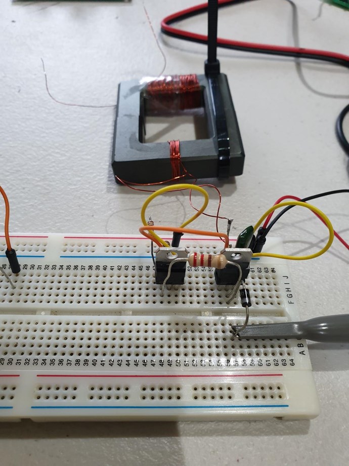
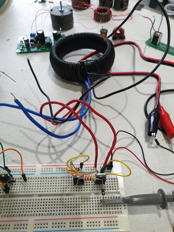
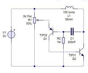
I have spent some time working with the different FETs. The following are my observations.

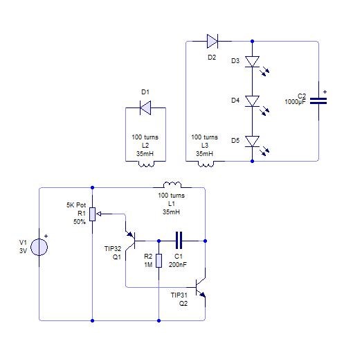
Using the IRF3205 the circuit works happily on a supply of 2V, But if I substitute the IRF840 the supply needs to be increased to 4V to get it to switch. This is a little confusing as the specs of both indicate a min threshold voltage of 2V - am I looking at the wrong specification here?

The knock on effect is the different supply voltage then induces a different frequency of operation for the coils / circuit interaction.

So then I explored that maybe I needed a higher supply to hit the required resonance? The first point of note is with the use of either FET as I increase the supply (up to a max of 9V which is the design) the current draw increases till a point where I burnt out the LEDs. I had hoped it would co operate and self run before this point laughing

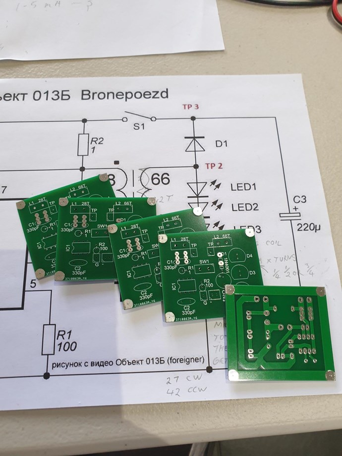
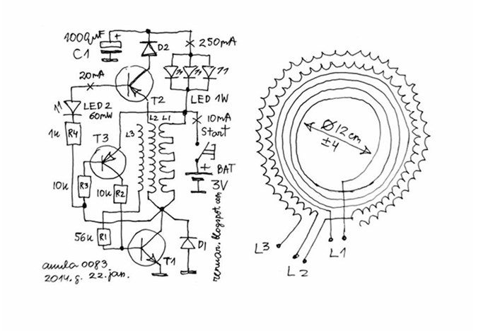
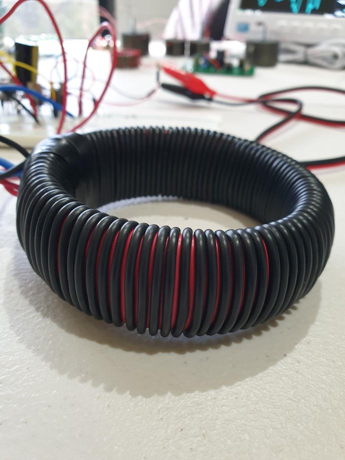
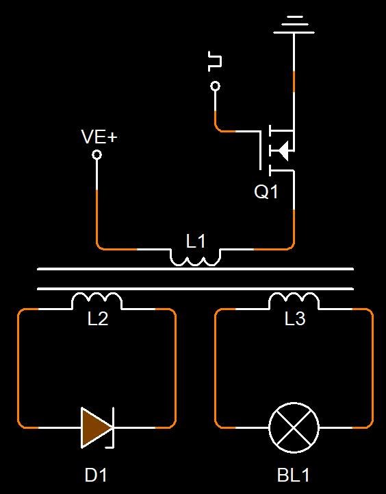
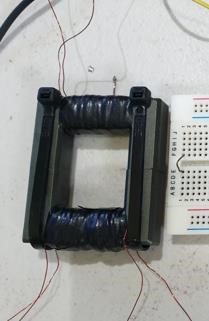
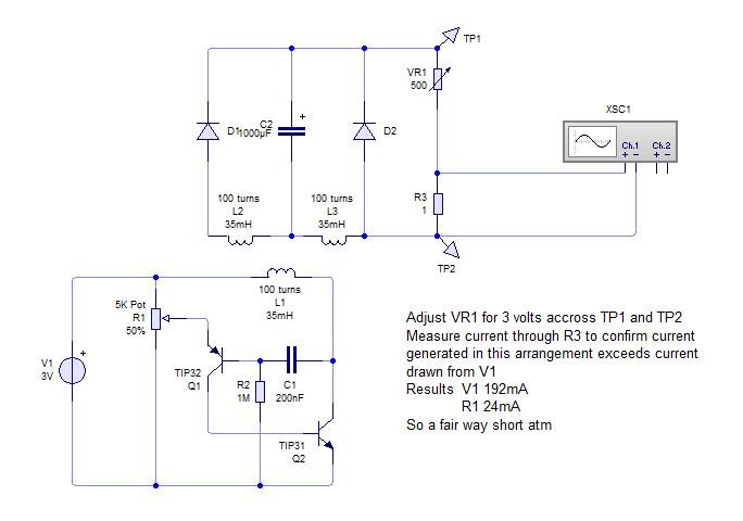
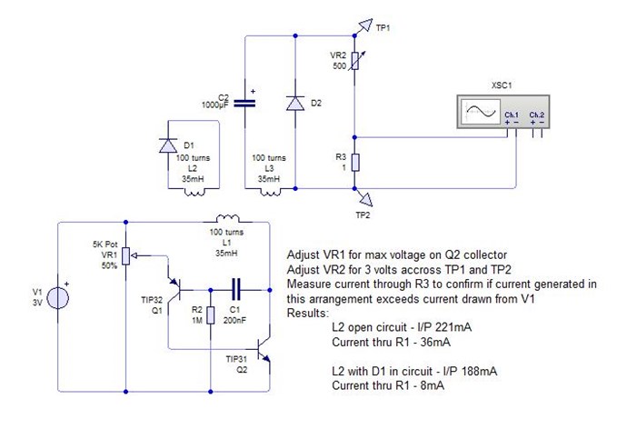
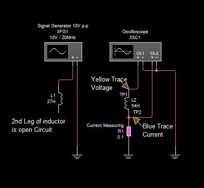
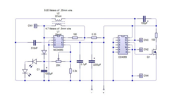
As Chris has pointed out many times it is Magnetic resonance that is required so we need to ensure the circuit operates in the region of this resonance. With this in mind I went back to measure the the coils I am using to see if this might provide some clues if I was in the correct range. The unloaded (open) measurements are:

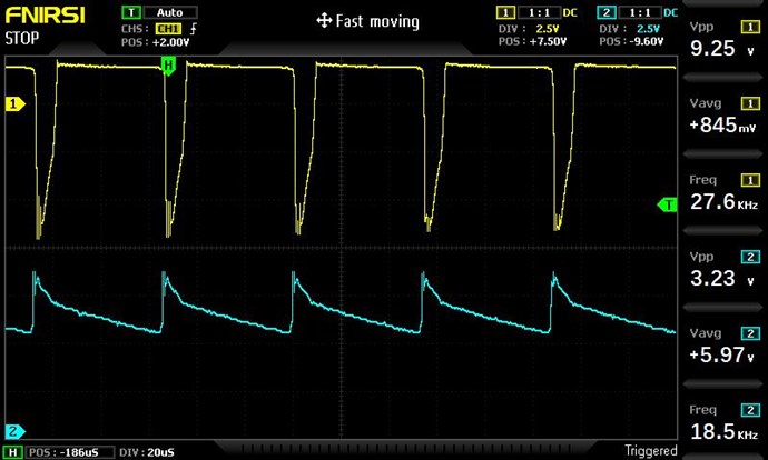
L1 28.9mH, 158uF, 0.7ohm - which calculates a resonant frequency of 74.48Hz = this is within the range of what I am able to tune the circuit.

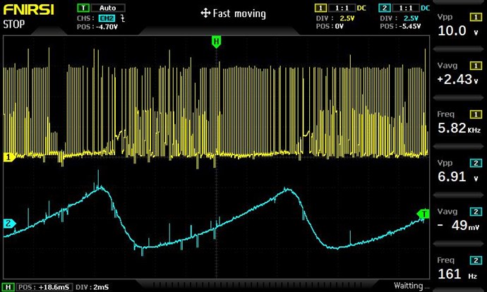
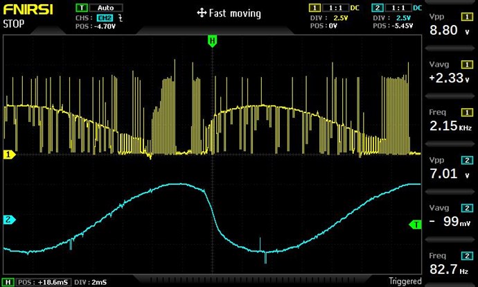
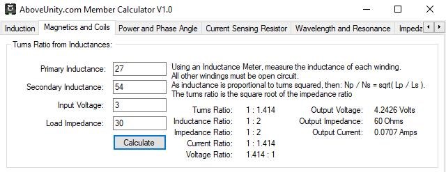
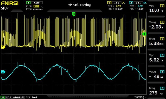
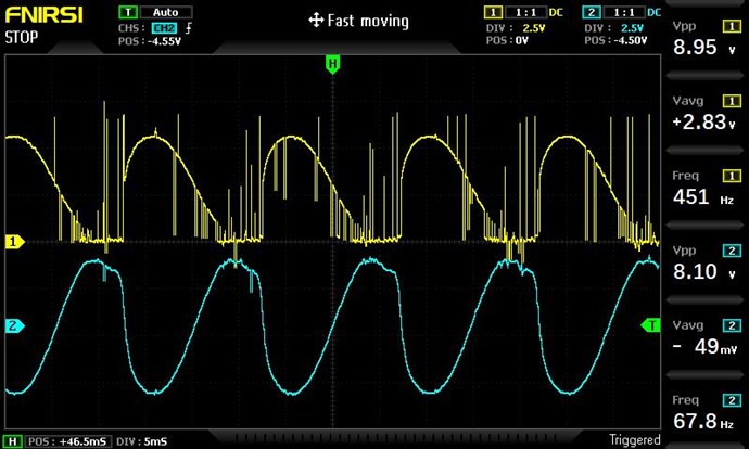
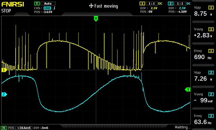
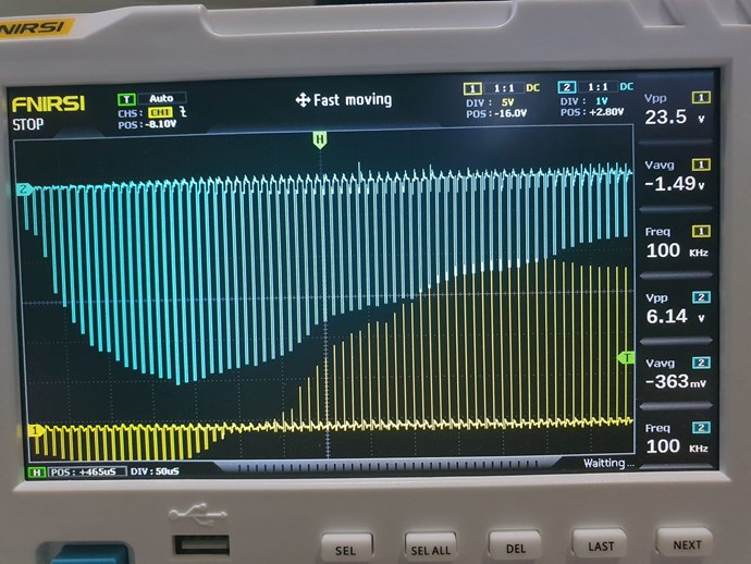
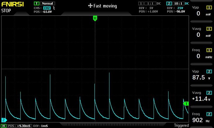
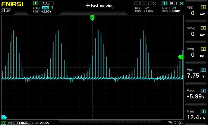
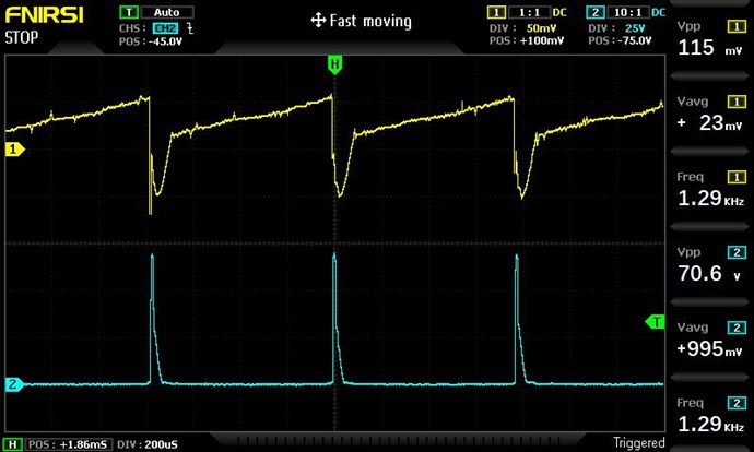
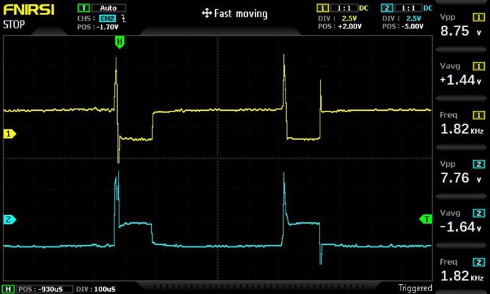
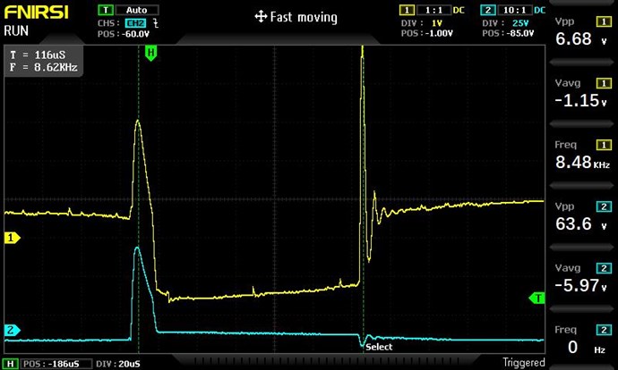
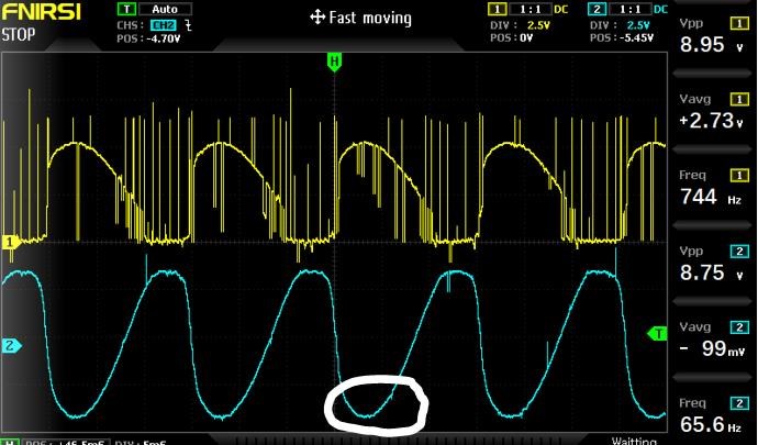
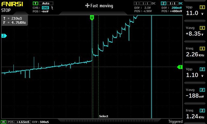
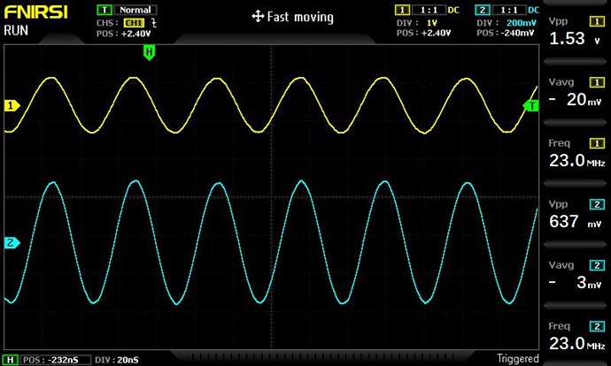
But this is where I need some direction to clarify my understanding. Firstly if we then connect L2 to the circuit as the load, the measured characteristics change (measure L1 with L2 in circuit, the resonant frequency result is 982Hz). Secondly it is my understanding the magnetic and calculated electric resonance do not necessarily appear at the same frequency and the interaction between coils and loads impacts this greatly. I have been attempting to confirm the point of magnetic resonance by scanning the input frequency to L1 with L2 loaded while measuring the current draw and response voltage, looking to minimize the current and maximize the voltage as a indication of the correct frequency to work towards.

I guess my simple question is - is there a process / procedure or calculation that is able to more closely identify the required design specifications to reach our goal? I feel that this may be the genius of Andrey, his knowledge and understanding is such that this answer is second nature.

I note also that working with various POC designs, many measurements and results are much clearer and predictable, than my experiences with this experiment. This is the Genius of Chris's POC work and guidance.

Anyway a quick update and more work to do.

Kind Regards

Brian

Jagau posted this 06 April 2022

Hi Brian


IRF840 and 3205 both have a min of 2v and a max of 4 volts for Vgs and that's normal.
To find an even match you will need to use other 840s that match your original 3205

Jagau

Brian posted this 06 April 2022

Thanks Jagau - much to learnlaughing

  • Liked by
  • Chris
  • Augenblick
We're Light Years Ahead!
Members Online:

No one online at the moment


What is a Scalar:

In physics, scalars are physical quantities that are unaffected by changes to a vector space basis. Scalars are often accompanied by units of measurement, as in "10 cm". Examples of scalar quantities are mass, distance, charge, volume, time, speed, and the magnitude of physical vectors in general.

You need to forget the Non-Sense that some spout with out knowing the actual Definition of the word Scalar! Some people talk absolute Bull Sh*t!

The pressure P in the formula P = pgh, pgh is a scalar that tells you the amount of this squashing force per unit area in a fluid.

A Scalar, having both direction and magnitude, can be anything! The Magnetic Field, a Charge moving, yet some Numb Nuts think it means Magic Science!

Message from God:

Hello my children. This is Yahweh, the one true Lord. You have found creation's secret. Now share it peacefully with the world.

Ref: Message from God written inside the Human Genome

God be in my head, and in my thinking.

God be in my eyes, and in my looking.

God be in my mouth, and in my speaking.

Oh, God be in my heart, and in my understanding.

Your Support:

More than anything else, your contributions to this forum are most important! We are trying to actively get all visitors involved, but we do only have a few main contributors, which are very much appreciated! If you would like to see more pages with more detailed experiments and answers, perhaps a contribution of another type maybe possible:

PayPal De-Platformed me!

They REFUSE to tell me why!

We now use Wise!

Donate
Use E-Mail: Chris at aboveunity.com

The content I am sharing is not only unique, but is changing the world as we know it! Please Support Us!

Thank You So Much!

Weeks High Earners:
The great Nikola Tesla:

Ere many generations pass, our machinery will be driven by a power obtainable at any point of the universe. This idea is not novel. Men have been led to it long ago by instinct or reason. It has been expressed in many ways, and in many places, in the history of old and new. We find it in the delightful myth of Antheus, who drives power from the earth; we find it among the subtle speculations of one of your splendid mathematicians, and in many hints and statements of thinkers of the present time. Throughout space there is energy. Is this energy static or kinetic? If static, our hopes are in vain; if kinetic - and this we know it is for certain - then it is a mere question of time when men will succeed in attaching their machinery to the very wheelwork of nature.

Experiments With Alternate Currents Of High Potential And High Frequency (February 1892).

Close