My Friends,
I am going to have a go at replicating the GLED of Andrey Melnichenko.
If this project helped you, please consider a Donation:
Please Note: My work, shared here: Chris's Non-Inductive Coil Experiment, is related to, the same concepts as, this work. But my experience outside of what I have shown you is limited. I have worked on this before, but it was a long time ago, and on a breadboard:
I am re-replicating this experiment for my own and others benefit. No guarantees here guys, ok. Lets just do our best here. I am sure we can do it again 
Some history behind the GLED, first designed and shown by Andrey Melnichenko and friends back around 2000. Some videos exist, the face of the person holding the GLED is Arthur Tränkle, currently the CEO of Steho Energy:
We have a thread here: Akula's circuits- is this the principle? that also has a LOT of information on this device! Its worth going and studding that thread also!
Akula, Roman Karnouhov, replicated the GLED and never gave Andrey Melnichenko any credit for it! Akula, Roman Karnouhov, did post this to the realstranik forum:
All schemes to develop and execute on principles of operation (Transgenerator magnetic field Andrey Melnichenko) and what to do with Pantyuhavu have!
Some months after the replication, Roman Karnouhov started working for Arthur Tränkle, and Steho Energy:
The Video Transcript:
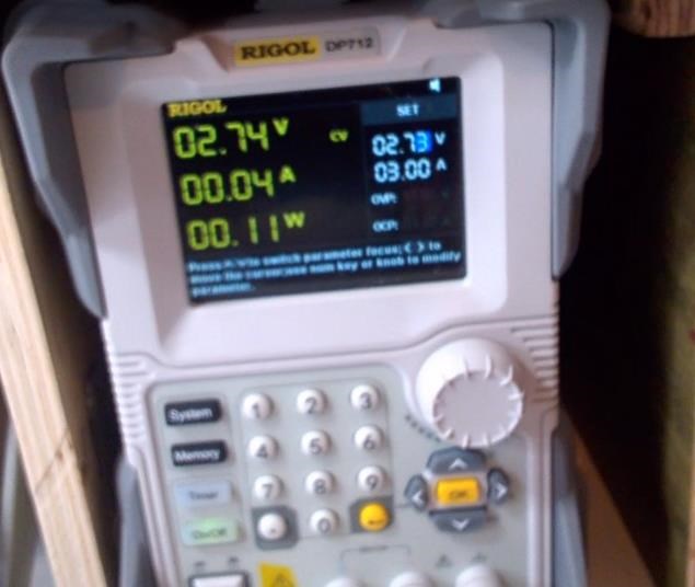
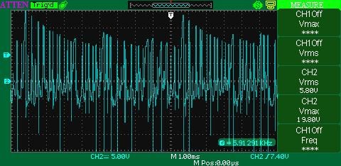
they don’t burn, but we have a voltage going on here goes 19 hertz 19 hertz is going on I'm not talking about what signals of their time and about his time about everything else I have no right we go to this spoon 1910 the power goes 2 and 6 volts and what do we see in our coils in our coils we see here the signal that the vadik showed, but I have it a little stronger since I’m just not the first time to assemble this design with a similar design so I have more serious fronts, that is, we feed 2 and 6 volts and we see that the pure moreover, we supply 2 and 6 volts and a frequency of 19 hertz, but this the transistor and what we see undamped oscillations, our coil, together with pyrite, it buzzes and at a cleanliness of 293 it becomes a little wrong this is 290 kilohertz here are our non-damped oscillations, that is, this is the beam now it’s on the collector then on the collector of this transistor it’s just we see our 19 hertz the whole set of work of the ether of a given coil design in automatic undamped oscillations oh well, now I think I’ll show the operation of the voltage, that is, now I will increase the supply voltage to That operation of our voltage stabilizer before they work on the diodes light up, that is, you can now add a little bit so 2 of 6 here are 2 and 6 and our LEDs are on, they light up and two of our undamped oscillations became even more than 10 volts here on the collector undamped oscillations with the frequency of the resonance firm and the overall design turned out to be 10 volts, that is, in principle, the record itself can now be made even without this generator, well, it is necessary for stabilization, since we have a load, there are nights, I can say wadik For you, but great successes, good luck, I’m glad that in just about a year and a half I see a person who with his own mind reached it with his own hands, launched the scheme, was able to stabilize this process and get the scheme so-called free energy, I won’t even collect the scheme for all unbelievers and bitches can consult with the author, he will tell you that this is the true work of this device to tell you more too I have no right do not be offended by all the questions to the author of this scheme, but a very original solution is generally very original Inalnaya, but only with this original solution we need to slightly change the design, that is, Vadik I can say for sure because this is not the first time I have assembled this design for such power and there are two but three LEDs in which your mistake was, it’s purely you will understand only you were the mistake in that you have two LEDs, but I didn’t actually consider it, maybe I didn’t see it, I don’t know, but I couldn’t turn up the power because you had two LEDs in parallel, you need to sequentially and here, at the output, raise a little voltage yes, of course, your return line will start up well and that’s all, but also what can I say? This is a microcircuit of working with this transistor that eats a lot, just eats the power of one of the LEDs, that is, it can be replaced with a simple multivibrator, it will be much more economical to form of what is needed here precisely with this generator, well, guys, see the free energy, he’s so very glad I’ll be talking with you, maybe even work together so that you don’t see something I even know a new share something very glad I will talk to you and indeed to discuss something interesting for the future, we
The Video Transcript:
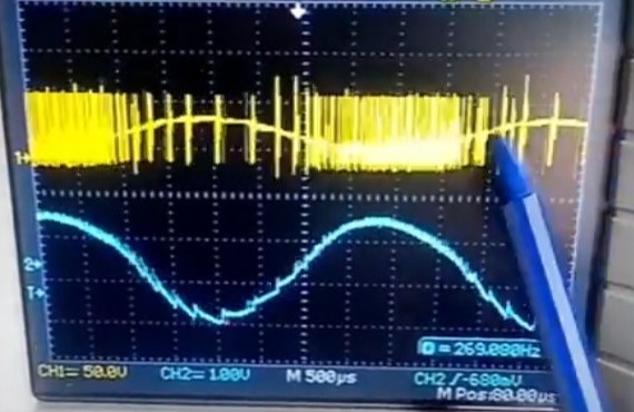
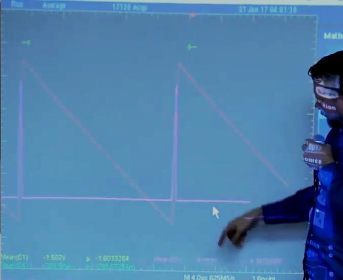
so well, what’s happened, I’ll show it’s most interesting, it’s not loving now, it’s not working at all yet, I haven’t completely caught up with all the signals, tested the working principle of forming a low-frequency resonance in seconds, that is, our face of cultures is output and this capacitor is what we have here it is here it is so here we have a series of bursts of pulses from them we see the low-frequency component and what’s actually looking for this thing is f**king erase three monsters I’ll rewind the general resonance of the fer Rita does not match for the formation of a low-frequency sinusoid I can’t raise the power then you have it for the last time I’ll be holy he would understand now we are looking for this one now it works like this
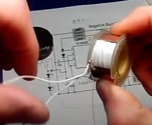
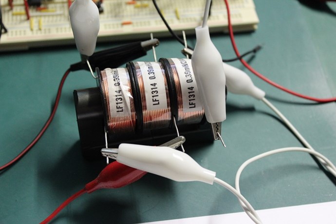
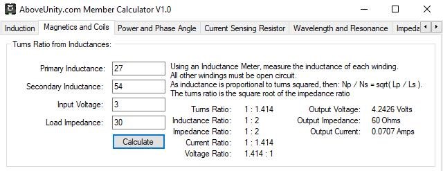
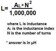
Observing the approximate lengths, where each unwind is approximately an arms length, about one meter, we get the following lengths:
23 arm lengths
26 arm lengths
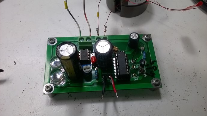
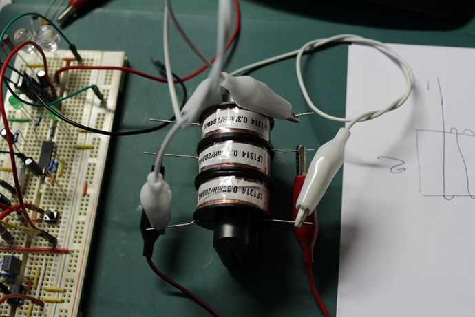
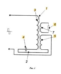
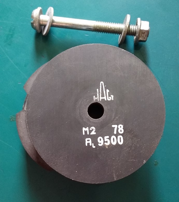
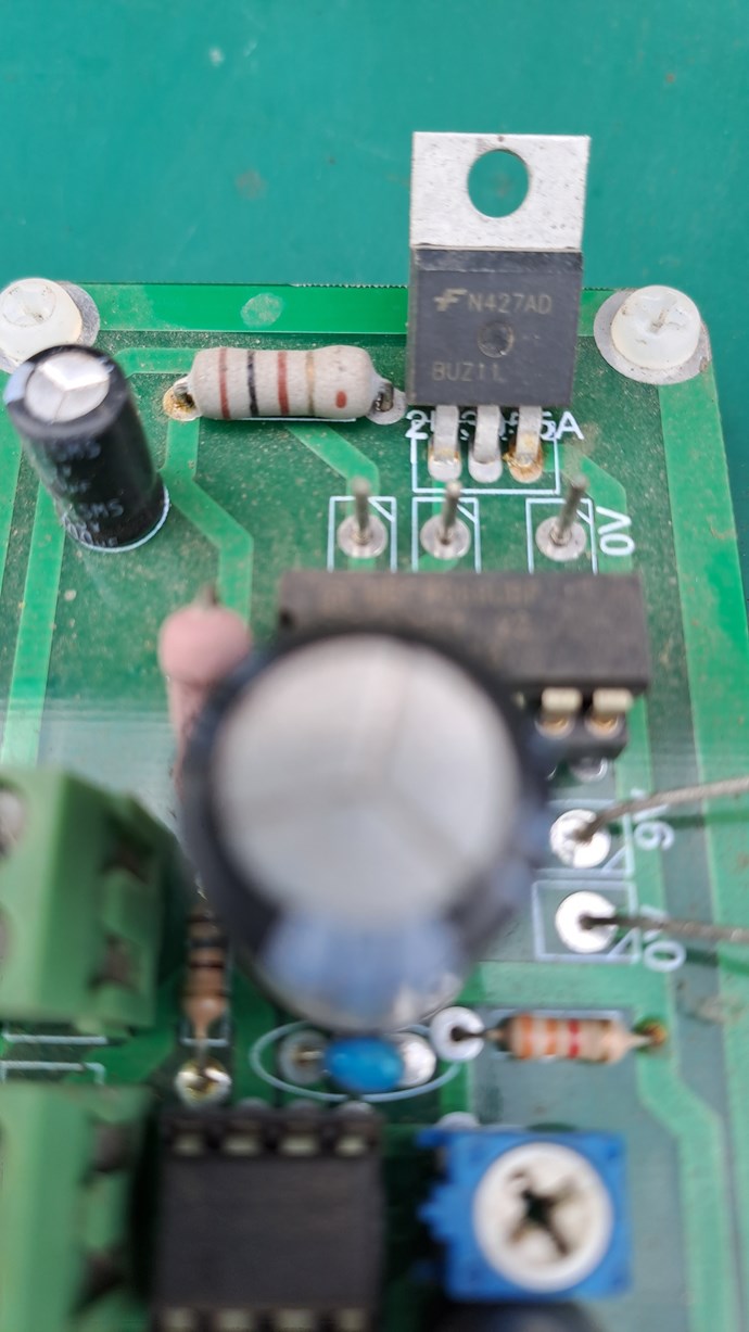
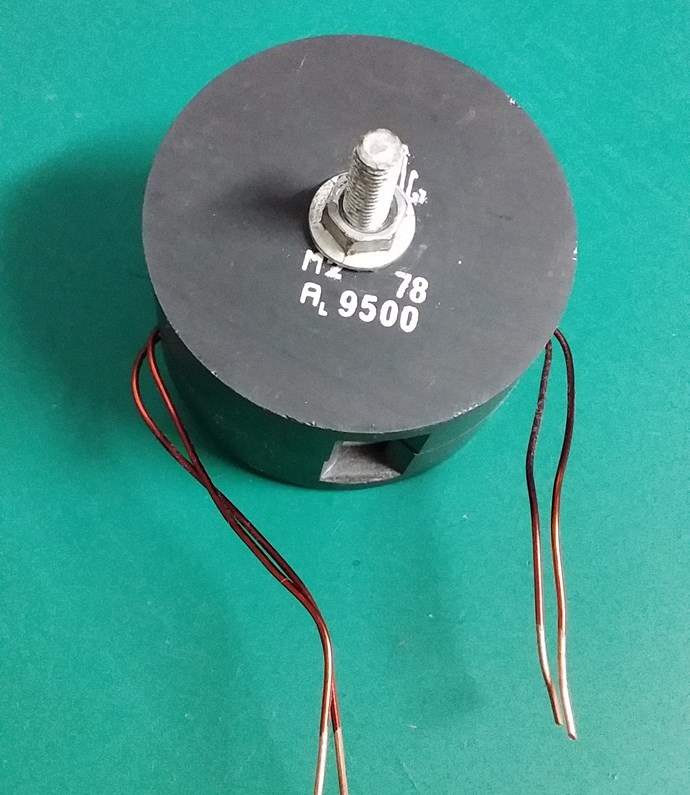
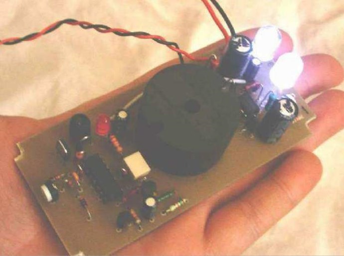
I have a Pot Core, one that you have seen before:
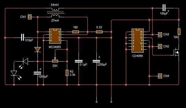
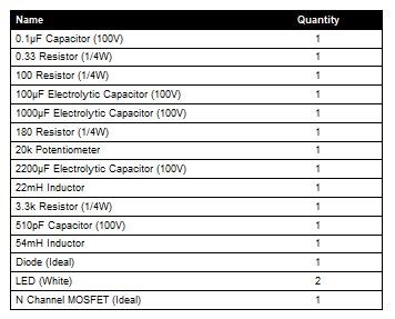
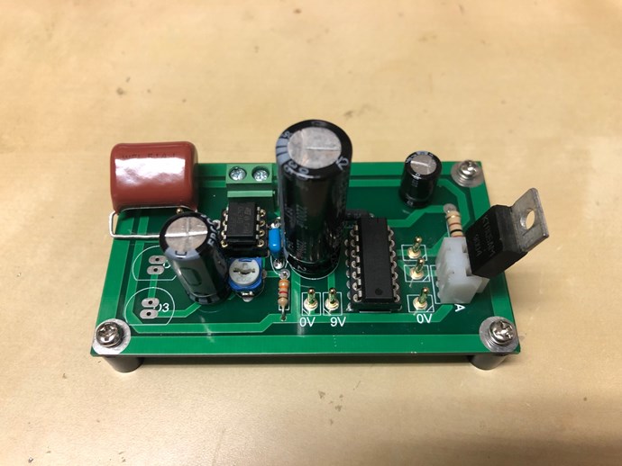
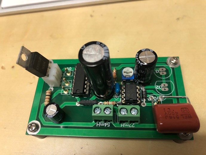
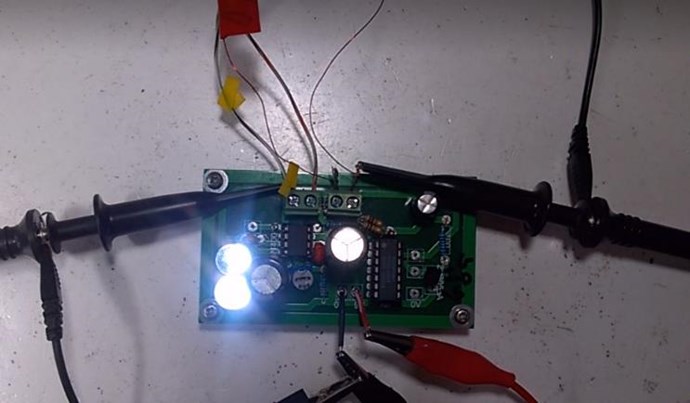
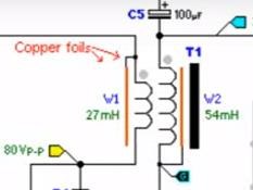
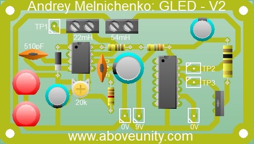
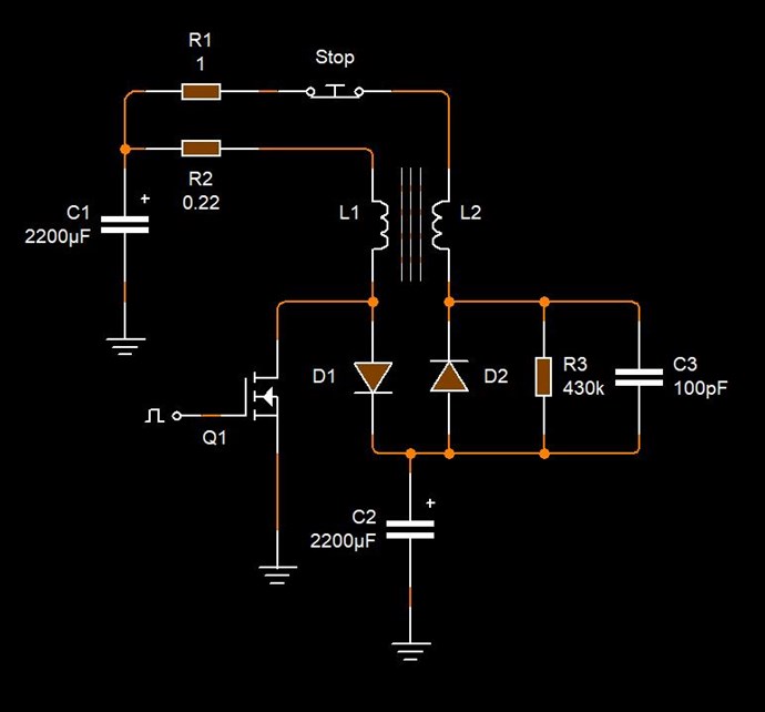
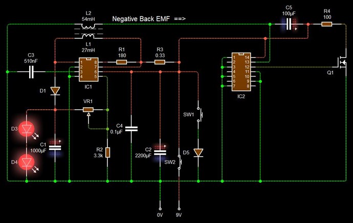
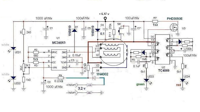
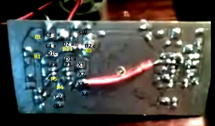
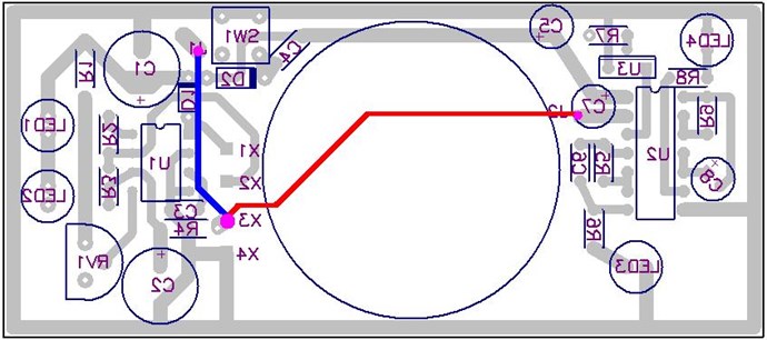
I have drawn the circuit and have the following design:
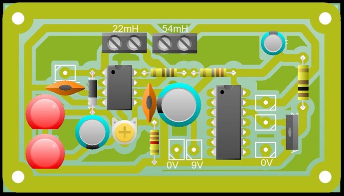
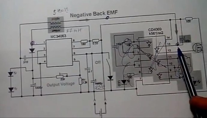
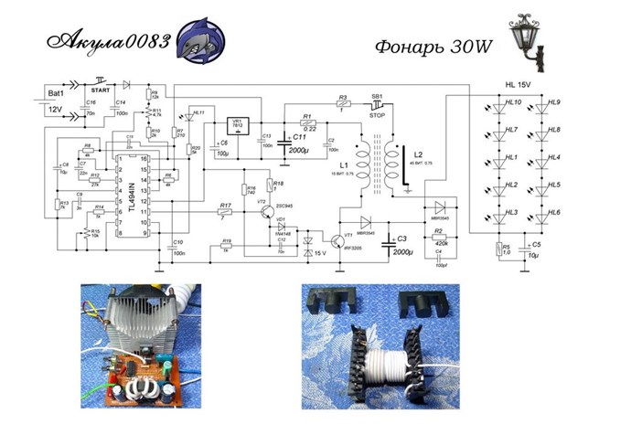
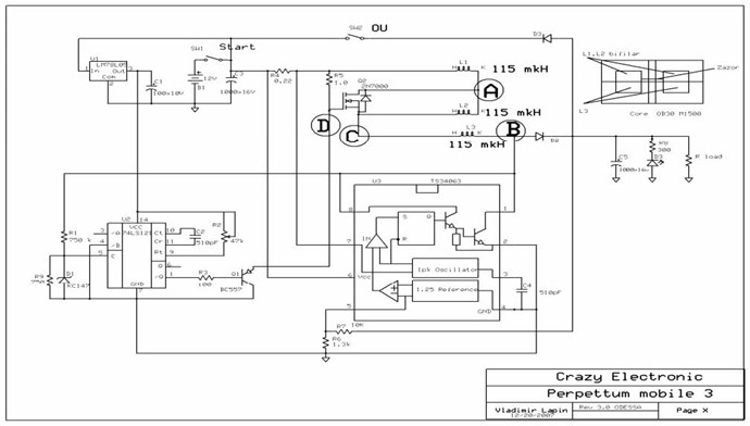
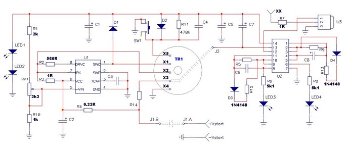
This is just a start. Any changes / improvements will be incorporated and a new circuit may be shown at a later date. This is a copy of Akula's Circuit:

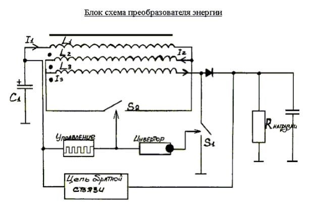
Which was a copy of Andrey Melnichenko's Circuit:

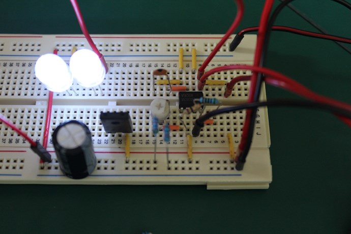
I have replicated this before, on the breadboard. I have had some successes with this circuit, but I thought I would make this a bit more evolved to show others. To try to help others advance! However, I can only do so much, I cant do it all for you! You need to so this for yourself!
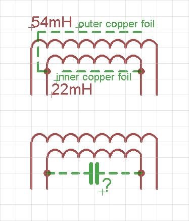
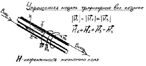
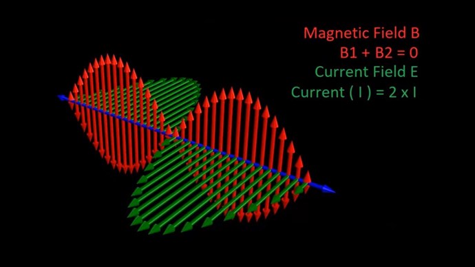
Equal and Opposite
I am going to continue harping on about the basics: Equal and Opposite!
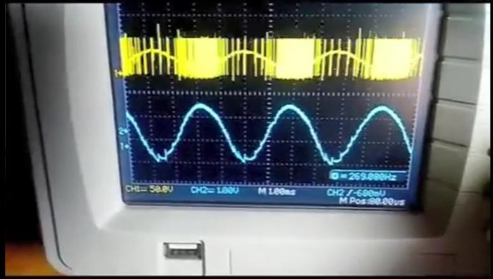
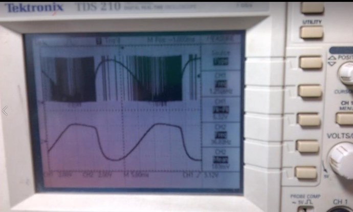
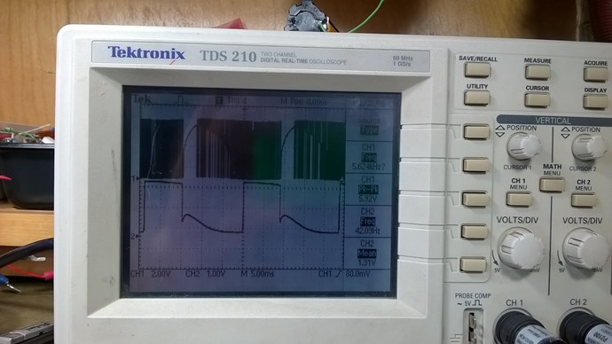
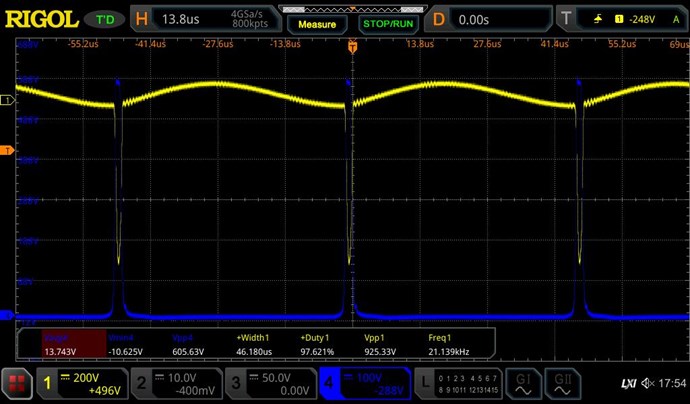
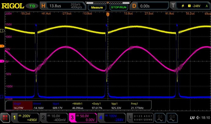
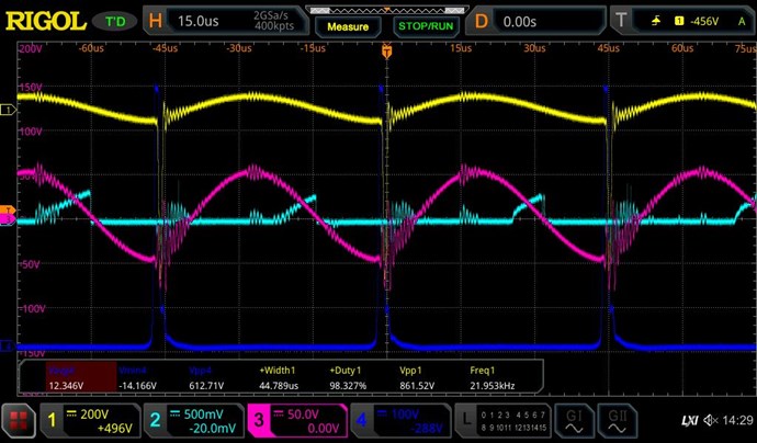
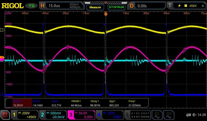
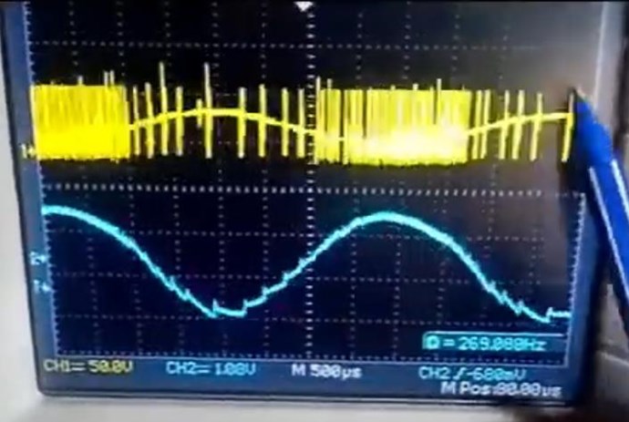
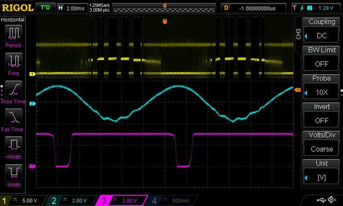
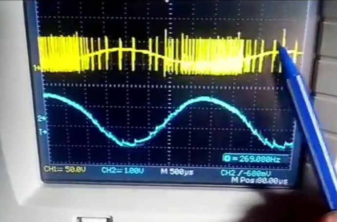
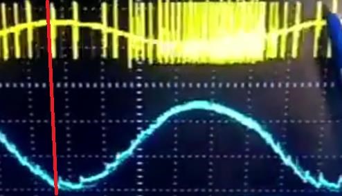
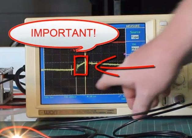
NOTE: The above schematic from Akula, he drew with pen, big dots, above. Each dot is a Test Point, where the Oscilloscope measures the Voltage at each point.
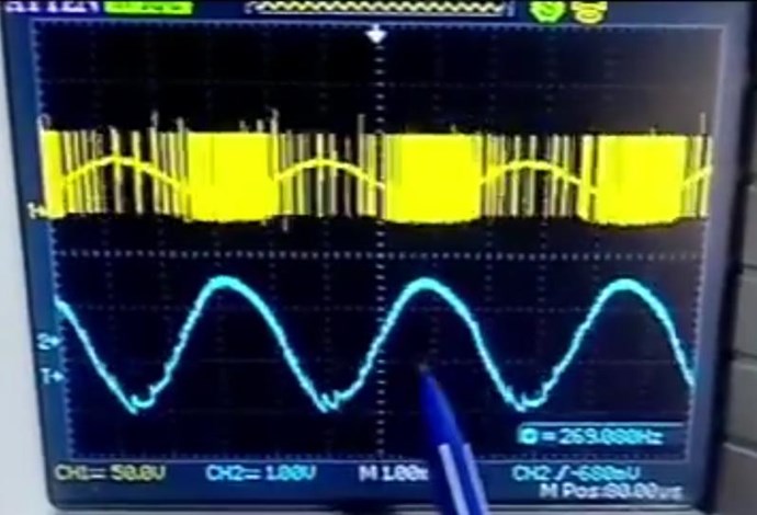
NOTE: The AC Voltage is equal and Opposite:
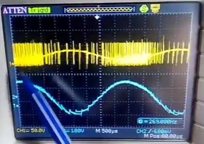
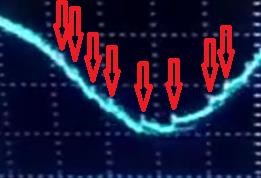
Also Note: The bottom waveform has a goodly degree of DC Offset!
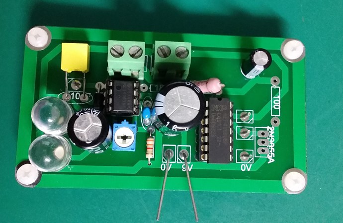
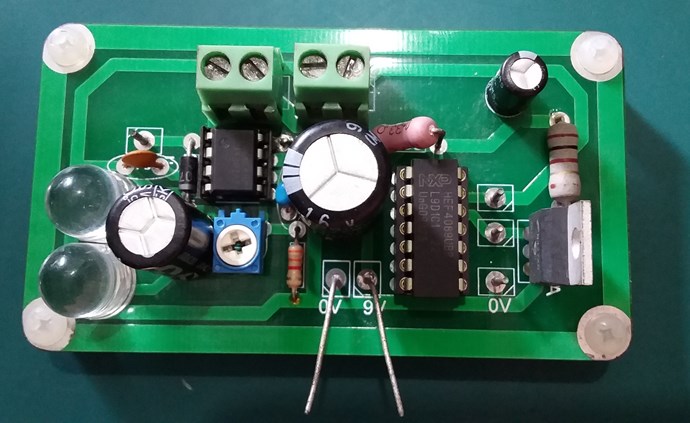
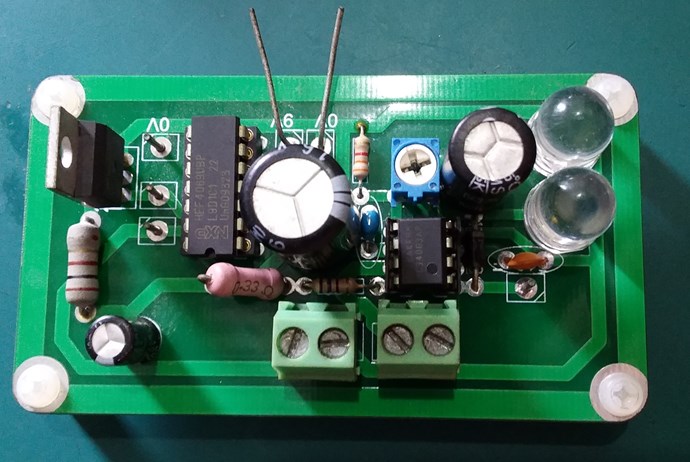
PCB Give Away:
I have some PCB's to give away, you pay for postage, from Aus to most parts of the globe its about 8 - 10$. PM Me and I will pick some lucky recipients! Its just a bare bones PCB, you purchase the components and fit as a kit for yourself.
I have most of the components already. I have the PCB's on order and they should be here in a few days.
Chris