Building a Smith Generator

  • 19K Views
  • Last Post 15 October 2022
  • Topic Is Solved
sampojoe posted this 12 January 2018

I am starting work on building a Smith Generator.  Thanks to your work here, I am getting the role of Bucking Coils on the circuit.  I found this link for starters, a pdf that purports to tell you how to build one:  

projectavalon.net/forum4/attachment.php?attachmentid=25399

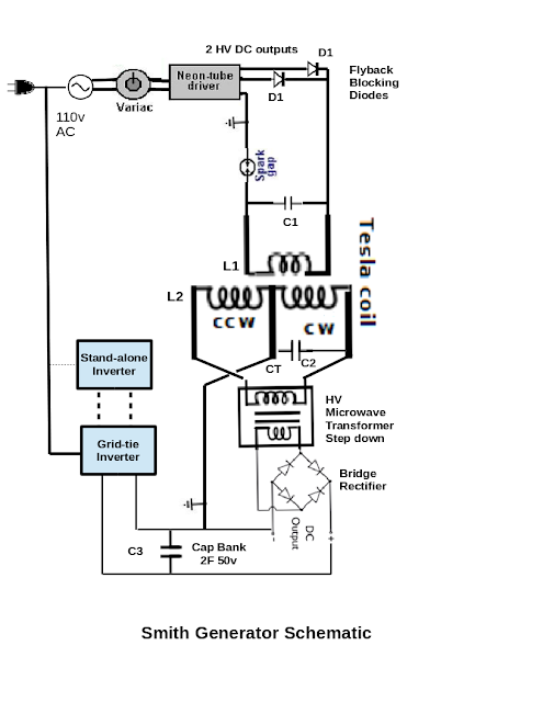
I extracted another schematic and made it an attachment below.  What they do not mention anywhere in the document is that coil L2 most likely is a Bucking Coil, as you have most eloquently shown here!  I guess they do say it is a "Tesla Coil".  I guess that could be a Partnered Output Coil.  I have seen similar schematics on youtubes by kdkinen, where he shows his replication attempts seemingly at least generating OU.  His schematics I can clearly see the Partnered Output Coils.  So with this understanding I think I will attempt a replication.   It seems very simple.  You use a 30 ma NST to get thousands of volts.  The front of the the circuit as shown uses a small inverter driven by a 12v battery to get 120v AC, which is fed thru a variac to control the input voltage to the NST.  The final output is supposed to be up to 8000v @ ~20A DC, as the L1/L2 is 4:1 step-up!   Pretty astounding.

I am not going to use a battery to run an inverter to drive the system.  I will just initially plug my variac into the wall.  You do need a real sine wave input for this.

So the front of the circuit feeding L1 starting with the output of the NST is grounded at the center point tap of the NST.  The output of the NST is rectified to extract the starting HV and then reconverted to AC with a spark gap tuned with resistors and caps to the coil L1 for about 31.5 kHZ AC .

Here is a hand drawn schematic online and in the pdf : Hand Drawn Don Smith Schematic

I got a little excited about solving the performance issues of the L1 circuit and clicked the solved button thinking it just applied to the post by Marathonman showing how Tesla built such circuits. But no, it got applied to the entire trhead, and is apparently a big database issue to correct.  So please ignore the green solved check!

Attached Files

Order By: Standard | Newest | Votes
sampojoe posted this 11 March 2018

As I have bothered everyone with my Tesla style DC asymmetric motor build, I was working on, I wanted give everyone some of my test results.  I built it on a Baldor frame and still have an untouched Edison style production ~1HP electric motor to compare it with.  These motors are industrial strength and run assembly lines and other heavy machinery, and operate on 60-90vdc as high amperage.  So I cobbled together two car batteries for 24v and compared rpm.  The production motor ran at a meager ~400rpm while my asymmetric built motor ran at more than triple the rpm coming in at about 1400.  Now I guess I need to build an electric car of some sort around it ;-)

  • Liked by
  • Chris
  • Augenblick
Jagau posted this 11 March 2018

Hi Sampojoe

Sorry, I could not answer you these days. About your question

I have a question about the quarter wave antennas used by the Don Smith Generator. Given that the frequency of the operation is 35.1kHz, the period is 28.49 microseconds (us). So in that time, the signal will travel 2135.3m, and q quarter wavelength is 533.8m.


I do not understand why all those who want to don smith system uses the frequency of the NST to do their coil, yet he says it in several places in his 40 page book I quote it to you at the moment (IN MY SYSTEM WORKING TO 220 MHZ )

Everyone want to make a L1 at 35.1khz, unfeasible!

In the section of Replication I will do an experiment with you if you are interested and you will be surprised of the result, I need a little time to explain it, I am not a good teacher but I'm going try.

jagau

Jagau posted this 12 March 2018

Dowload the Patrick J. Kelly book see page 42 and page 43

About earth electrical system 2 and my 220 mhz system

  • Liked by
  • Chris
  • Augenblick
Jagau posted this 13 March 2018

I found this interesting article about,

Natural electric field of the Earth

https://en.wikiversity.org/wiki/Natural_electric_field_of_the_Earth

I quote them;

The surface of the Earth is negatively charged, carrying 500,000 Coulombs (C) of electric charge (500 kC), and is at 300,000 volts (V), 300 kV, relative to the positively charged ionosphere. 

There is a constant flow of electricity, at around 1350 amperes (A) [approximately 1100 A, and resistance of the Earth's atmosphere is around 220 Ohms. 

This gives a power of around 400 megawatts (MW). There is no feasible means to harvest this power, which in any case averages a mere 0.8 microwatts per square metre of the earth's surface (compare solar radiation which is one billion times as large).

The charge is maintained by the stream of charged particles from the Sun. This process affects the ionosphere, as well as the troposphere, possibly causing thunderstorms. The electrical energy stored in the Earth's atmosphere is around 150 gigajoules (GJ). The Earth-ionosphere system acts as a giant capacitor, of capacity 1.8 Farads. The Earth's surface carries around -1 nC of electric charge per square meter.

 And what NASA sapceflight.com forum think  about that :  https://forum.nasaspaceflight.com/index.php?topic=24963.0

 In fact what it means is that Mr. Don L. Smith is telling the truth and he is very credible.

  • Liked by
  • Augenblick
  • ISLab
sampojoe posted this 15 March 2018

Hi Sampojoe

Sorry, I could not answer you these days. About your question

I have a question about the quarter wave antennas used by the Don Smith Generator. Given that the frequency of the operation is 35.1kHz, the period is 28.49 microseconds (us). So in that time, the signal will travel 2135.3m, and q quarter wavelength is 533.8m.


"I do not understand why all those who want to don smith system uses the frequency of the NST to do their coil, yet he says it in several places in his 40 page book I quote it to you at the moment (IN MY SYSTEM WORKING TO 220 MHZ )"


jagau


Well many videos of Don have him quite clearly talking about using an NST, and quite definitely stating you can get 160Kw out it.  Dummyload has PM's me and said Don said to go ahead and just build it and the NST frequency would drive it.  It may be easier to build it out at this point just to see.  Is it all in the partnered output coil arrangement or not?  That could amplify the current whether or not its a quarter-wave antenna, as we know induction will occur between the coils.  It is arguable that a quarter wave antenna would have better  performance, but Don's COP's are truly mind-boggling.  So Jagau, where do we get these 220MHz oscillators?  If we build that circuit, I am afraid that would take me a few months more.  But if you have a circuit handy, I am interested.  I think I can get to an NST demo in a matter of weeks.  At Don's insistence of using an NST in his videos, I could only assume you can make a compromise here and forego the use of a quarterwave antenna.  If you can get a spark gap to work with full-wave rectification, we could operate 70.2KHz, but still a far cry from 220MHz.  But the number of turns in L1 and L2 in the videos and the pictures on this thread would seem to fit the MHz range.  Is that microwave?

  • Liked by
  • Augenblick
Jagau posted this 15 March 2018

Hi sampojoe

You're absolutely right, for the final system of Don Smith we have to use a NST and a spark gap. In my post I just said that I used a different approach using lower AC voltage and trying to understand all the subtleties of the circuit with different frequencies before using an NST and a spark gap.

In the low voltage circuit that I am trying to experiment the final output frequency of L2 is not yet decided and in my case I experiment. However Don Smith guides us in these videos and documents without telling us exactly how to do it. Many have tried to do the D.S. circuit without succeeding and have discouraged other experimenters because they failed to do so.

Fortunately Chris has made us a great site to exchange our ideas and concept and I think that's the purpose of this thread, thank you Chris.

The dipole L2 is at half wavelength and the primary side which is the quarter-wave of L2 / 4 = L1 is inserted inside L2. We use the same concept. What is different is I do not use, at least for the moment, a NST and a spark gap since the voltage is too low to make a spark in the gap.

I believe that Don telling us that his system operates in the 220 mhz is true, but the subtlety is that it operates at a much lower harmonic frequency, this is my opinion it is not necessarily the truth. In search mode everything is possible. Between 30 mhz and 300 mhz are the frequencies VHF, between 3khz and 30 MHZ are the frequencies LF, MF and HF. You can find this in the charters of the frequency spectrum. Microwave are in the same range as you microwave on your home at 2445 mhz or 2.445 gigahertz.

I hope to continue to exchange with you and reach the final goal

  • Liked by
  • Augenblick
  • ISLab
sampojoe posted this 20 March 2018

Calculating the L1 coil inductance of Don Smith's Early Device

Using my college text to calculate the resonant values in an RLC circuit, (Foundations of Electromagnetic Theory), the formula is:

ω2=1/LC


Notice that Resistance is not present in the formula. However it is prominent in figuring Q value of a circuit. The lower the resistance of an RLC circuit, the higher the Q value and the sharper the resonance peak. This may be a reason that Don seems to use heavy wire on L1.


In the photographs of this generator, the capacitance used is clearly on display, and we know the frequency of the NST, so that the inductance of the coil may be solved for.


L=1/C ω2


Units are Henrys and Farads. For coil L1 the inductance of Don's display model calculated from this formula is 4 mH.


So now we must reverse engineer what a coil of this inductance looks like. I have 2 different formulas, one from Don's book, Resonant Energy Systems, and another from Navy Bupers manual, Basic Electricity.


The formula on the last page of Resonant Energy Systems is:


L = d2n2/ (18d + 40l)


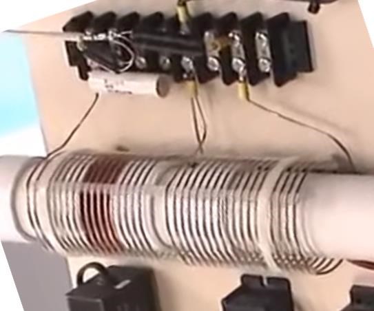
where l, coil length and d, diameter, are in inches, and n is the number of turns. Don seems to indicate in a number of videos that standard PVC pipes are used for forming L1 and L2, and so the diameter of a L1 is estimated at 2.9” and length at 6”. This formula for turns calculates at


n = 376

The Basic Electricity formula includes Permeability μ for Non-Air Core Coils. Permeability can be values even higher than 1000, with ferromagnetic cores concentrating the lines of force. Linear dimensions are in cm and inductance in Henrys.


L=.4πN2μA x 10-8

l

Assuming that substituting 1 for permeability is acceptable for an air core, and solving for number of turns,


N = 340


Results are comparable. You can play with coil length as you can see with thick wire that Don seems to use, it looks impossible to get this amount of turns in such a short coil. There seems to be a big discrepancy.  I intend to research my college texts for additional formulations, but the question of resonance in something approaching the presented pictures of the Smith Generator makes me wonder what the next step is.  Higher harmonics?

  • Liked by
  • Chris
  • Augenblick
Jagau posted this 21 March 2018

Hi Bob

Indeed a good grounding makes all the difference. I'm not talking about the ground all we have in our home power outle tbut from an 8 foot ground rod inserted into the ground in the back yard, this makes the difference.

In recent days I have not done much forums, I have successfully realized the experience of Dr. Konstantin Meyl that strangely resembles that of Don Smith and Tesla Magnifying Transmitter.

I reached with this experience more at the ouput than at the input, the most ably in this experience is thatit can be done in low voltage to study the smith donation system without burning your fingers and achieve a very interesting goal.

Indeed a good grounding has made all the difference, proof to support!

Jack


Jagau posted this 22 March 2018

HI

20 years later 2 universities (from italy and russia) have redone the Meyl experience, with components that can be easily found. It is quite simple to realize and very informative, it is very surprising to see the two leds connected antiparallel on and to be able to check the gains in current and voltage.

If you want to build it see attached file.

Jack

Attached Files

sampojoe posted this 22 March 2018

So I am going to take that tuning a Don Smith circuit means setting the capacitance in conjunction with the coil inductance to get sufficient charge on the circuit in one pulse of half-rectified NST output such that a sparkgap fires.  Perhaps I will try to match a quarterwave length of a 10th order harmonic of 35.1Hz.  This falls within the physical layout of the system he has shown so many times.  And also the number of turns on L1 I will approximate to the pictures and look into the benefit of introducing a ferrite core.  And as Don states, the 4:1 ratio of length for L1:L2 provides an almost automatic resonance?  It seems he just threw on a certain capacitor of .5uF and it gave him the needed difference to get some resnonance?  dummyload has informed me that on one video of the  "Donald L Smith Inventors Weekend 2001" at about 20m, Don says something like just make it "look nice" and it will work... (If you use a real tesla coil with a partnered output coil/bifilar pancake coil?)

  • Liked by
  • Chris
  • Augenblick
sampojoe posted this 26 March 2018

Part of Chris's Post

Re Wire Gauges:

Wire Gauges are important, basically the Wire Gauge determines the Resistance of the Wire. However, the rules you outlined: "A rule of thumb followed by most Tesla Coil builders is to have the same weight of copper in the L1 and L2 coils" - might be something to be cautious of. Floyd Sweet did not show this rule: 48 Turns #28 to 240 Turns #20...

-------------------------------------------------------------------

If I try to use a harmonic to create some resonance, then the quarter wave antenna approach nay also be applied.  Using 6ga - 12ga combo means one wire is almost exactly half the diameter of the other.  if the coils are the same actual weight, then, by cross-sectional area calculations, the length of L2 will be 4 times longer, but I think I will just measure it rather then weighing it! ;-)  Of course Don always talks about 4:1 will automatically "tune" the L2 antenna/coil.


  • Liked by
  • Chris
sampojoe posted this 29 March 2018

My L1 and L2 construction details

For L1, it looks like the 10th harmonic has a quarter wavelength of 6.8'.  So at about a diameter of 2.75", I calculate I need a coil with 9.5 turns.  Using 6ga wire.  So I will need to build L2 out to 2 halves at 13.68' each.  Each L2 half coil will be ~15 turns at a 3.5" diameter, using 12ga wire.  If I use a ferrite core in L1 with a permeability of just 400, I think I can get resonance there, as calculated in a previous post! (using the Basic Electricity formula however)  Resonance in L2 seems to be another story.  But since the ferrite core would occupy a smaller cross-sectional area for L2, it would have a smaller permeability.  That is what is needed, but L2 still only needs a permeability around 100 for resonance there.  OOPS  All calculations are using 35.1 kHz.  Should I be using the 10th harmonic?  35.94 MHz...  Well I'm punting...

  • Liked by
  • Augenblick
Marathonman posted this 29 March 2018


I don't want to bother everyone's work here but i found this circuit from Tesla in an old book that could be a substitute for the NST everyone is looking for. look at the frequency change after the spark gap, it went from 60 hz to 100,000 hz.

just a thought.

Marathonman

Attached Files

  • Liked by
  • Augenblick
  • ISLab
sampojoe posted this 07 April 2018

Hi Mman, wow seems like even 60cps will do a good job in my interpretation if I am correct.  So lets see, energy goes up with the square of the frequency, so the higher the better?  And double wow, It eliminates the need for the NST, So just plug it into 110v wall socket from the power company and get ?? COP return on the power company.  I like the simplicity.


  • Liked by
  • Augenblick
sampojoe posted this 07 April 2018

L1 Coil Redesign Thoughts

Using the design features of my previous post, the L1 coil would have 9.5 turns, using a 10th harmonic wavelength. With my wire coming in at about .25” thick with insulation, my coil length would be only 2.5” long. This seems kind of smallish upon examination of the pictures we have. It seems Don's L1 coil would be closer to 5” or 6”. If I look at the wavelength of the 9th harmonic, my L1 would be about 5” long at 19 turns. L2 construction would become more tedious then having to be 2 halves at about 27' of wire each, and 28.75 turns each. Each half would be 7.5” long with .25' spacing. Oh well gotta bite the bullet. I cut some wire, and hate to buy for the total length over, so I may be welding it back together.  Using harmonics may not even matter, it might make the difference, or somewhere in between.  So using a few brain cycles over it and a little extra copper seems like I should make the investment.  This would seem to bring L2 into the right size also.  Incidentally, upon trying to count the turns on Don's L2 it comes at 19 turns per half.   Overall Don's is smaller.  I have decided to make my calculations for C and L revolve initially around resonance calculations for 35.1 kHz of the NST as opposed to the 9th or 10th harmonic frequency. 


  • Liked by
  • Augenblick
Marathonman posted this 07 April 2018

AS Tesla was the master in his domain i would say yes as the frequency at 100,000 hz  could not be better in this case. this connected to the L1 would achieve the oyster one is seeking.


Marathonman

  • Liked by
  • Augenblick
Enjoykin2118 posted this 09 April 2018

 Attached

Tesla The_True_Wireless

Tesla Effects of Statics on Wireless Transmission


ps: If Tesla secondary is in partnered configuration or not,it must be tuned to parallel resonance point, Tuning via additional capacitors (asymmetric types used by Tesla ), at top and bottom of secondary , introduce additional phase shifts in each bransh, to achieve the critical frequency, at which Magnetic HZ field (scalar wave) was generated. 2 Phase shifts are in fact 2 timings, for each half of partnered secondary, Study HZ antennas design how to at this link: http://www.eh-antenna.com

Regards

Enjoykin

Attached Files

  • Liked by
  • Augenblick
Marathonman posted this 09 April 2018

Thanks for the link.

Are you referring to a second secondary added to the circuit above in a partnered output configuration?

Marathonman

  • Liked by
  • Augenblick
Enjoykin2118 posted this 09 April 2018

Yes.

Regards

Enjoykin


  • Liked by
  • Augenblick
Enjoykin2118 posted this 09 April 2018

Magnetic HZ field (scalar wave) in action. Old excellent Tesla technology.


  • Liked by
  • Wistiti
  • Augenblick
sampojoe posted this 11 April 2018

My L1 Coil Construction

Here is my L1 coil holder beside my 6ga bare wire on which I am slipping vinyl tubing for insulation.

https://4.bp.blogspot.com/-zDKh8ipKUb0/Ws5e8bHlgoI/AAAAAAAAAIw/luQ4Zi3DyQsuCgaN090i0Pr6JJujs9HGQCLcBGAs/s640/IMG_2002.JPG

Drilling an exit port at the bottom of the black form and cutting a starting slot at the top starts the L1 wind operation, CW from the top.

https://1.bp.blogspot.com/-5-QRmvAtYRA/Ws5fB0cDFvI/AAAAAAAAAI0/tuXT6R_2_NAkcZ8eWiWJDtEKqsa7m4weACLcBGAs/s640/IMG_2003.JPG

Inside L1 coil with one wrap complete

https://3.bp.blogspot.com/--_R8GpRhslU/Ws5fFvdBkyI/AAAAAAAAAI4/GbhdZehGM9sWEsGGZnRnoTTDHu1XN7-MACLcBGAs/s640/IMG_2004.JPG

L1 wrap half complete

https://4.bp.blogspot.com/-0b2BqK5VhwM/Ws5fMs4FdpI/AAAAAAAAAI8/rvm3GDBN79IV8jO9l-RUYC9ofCUCp4rjQCLcBGAs/s640/IMG_2005.JPG

L1 coil 19 turns, needs clamp

https://1.bp.blogspot.com/-pDO9hYKgr4U/Ws5gx_I2M2I/AAAAAAAAAJQ/-dhT6xr6bi4R1y4mP5uMJnmQQtwDYaXSQCLcBGAs/s640/IMG_2010.JPG


  • Liked by
  • Zanzal
  • Augenblick
Enjoykin2118 posted this 13 April 2018

Tesla had always used one turn primary coil. See the picture.

Massive A3 or A4 copper plate (or bigger) is enough for exciting the secondary coil with in series connected extra coil. Both secondaries were connected in partnered configuration CW-CCW or CCW-CW. On top of exciter coil should be assymetric capacitor with respect to the ground. Usually toroid or large metall ball.

What is the most important is very sharp mono-pulse/pure potential (compression wave or unidirectional pulse) so fast that there isnt running any conduction current through the primary. All electrons from outer orbits (same as inner) of copper crystal latticer must stand in place, or precise play the twist under the strike of pure potential impulse. Only the pure potential must be present in primary.To made this Tesla introduced Magnetic Quenching Spark Gap, with two powerful megnets to quench the arc between two gap electrodes. This Tesla way is probably the best way to achive longitudinal induction in partnered secondary. Minimum potentional amplitude shouldnt be less than 7kV. This was experimentaly estimated by Edwin Gray.

Tesla worked with 12MV potentials in primary.

Regards

Enjoykin 

  • Liked by
  • Augenblick
sampojoe posted this 13 April 2018

Hey Enjoy, I would need the Tesla Patent to begin to understand this diagram.  Maybe they are in your attached Tesla articles, which of course, look very interesting.  Thank you for those.  As of now, I am just trying to reverse engineer Don's generator, and I am estimating the L1 design at this point, and just trying to get some harmonic resonance at this point...  I don't have any more details on Don's design right now.  It seems Partnered output coil pairs can have many different configurations depending on the desired design goal.  I am optimistic that energy can be harvested in a variety of voltages and frequencies, even if not perfectly tuned.

  • Liked by
  • Augenblick
sampojoe posted this 18 April 2018

L1 Circuit Assembled and First test

Here is my L1 coil holder beside my 6ga bare wire on which I am slipping vinyl tubing for insulation.

https://2.bp.blogspot.com/-_7I2c5A01M8/WtdTKDWKX0I/AAAAAAAAAJ4/gvjhU9UMi1cgEn_NveuIiQ2k1PKgfZ7xACLcBGAs/s640/L1CircuitAssembled.JPG

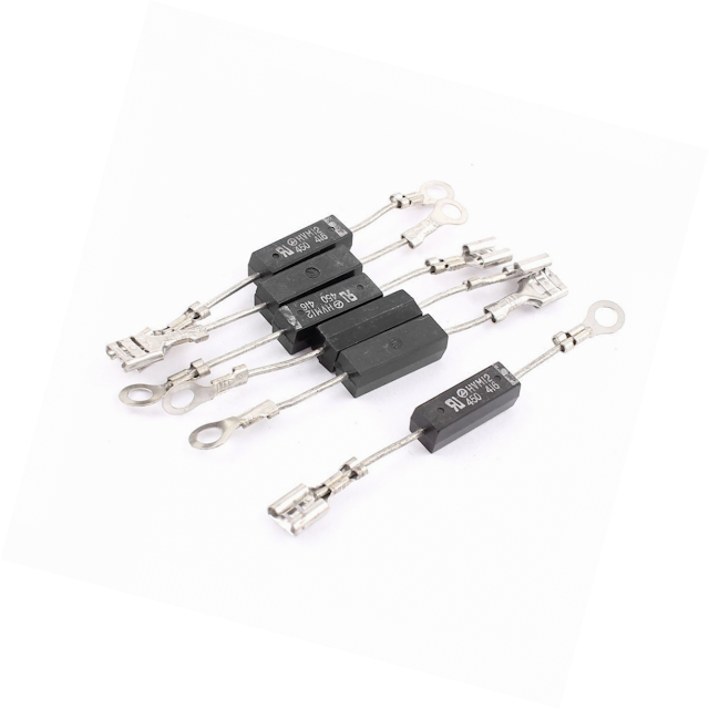
My VOM only can take 600v.  When I crank the variac up to 10vac input to the NST, I get 376~vac out of the NST.  As I cranked up to about 25v, I started getting some sparks at relatively slow rate of a few cps.  As I cranked up the voltage to about 40v on the variac, something went, and the sparking stopped.   The HV rectifiers don't seem to respond to normal diode testing, as I have spares, but I suspect they went.  They are HVM12 12kv 350ma microwave oven rectifiers, so they should not have been affected, (except for high flyback voltages?)

HVM12 rectifiters

The NST is still working.


  • Liked by
  • Zanzal
  • Augenblick
sampojoe posted this 18 April 2018

Ordered some higher voltage rectifiers, 20KV.

2CL20KV 30mA High Voltage Diode Rectifier HF Tesla Coil

 xEAAOSwmWVasOUo">2CL20KV 30mA High Voltage Diode Rectifier for HF Tesla Coil from ebay

  • Liked by
  • Zanzal
  • Augenblick
Marathonman posted this 19 April 2018

Sampojo;

 Do you think the Diodes frequency response was slower than the frequency of the NST and that's why they fried.

Just a thought. MOT diodes don't have to be very fast in their intended usage.

Marathonman

  • Liked by
  • Augenblick
sampojoe posted this 19 April 2018

All I know is they quit after a few minutes as I increased the voltage, and did have a very slow spark rate, which could be due to low voltages taking longer to charge the cap.  I can only estimate I was about 30% full power, so maybe doing a couple thousand volts at least.  I thought that maybe the circuit might have flyback voltages that exceeded their design, but I can see frequency might be a consideration.  But Microwaves do operate at near gigahertz range come to think of it, and I may have seen where they go up to 2 gig.  I am short of high voltage test equipment, and looking for some probes.

  • Liked by
  • Augenblick
Marathonman posted this 20 April 2018

There is no diodes on the magnetron side because of the high RF signal.  they are at the input side which is high voltage low signal. the frequency of the signal before would be that of the country you live in.

the signal then gets bounced around the magnetron which increases the signal through the roof so yes they could of fried as their response time is to slow. your new ones should do fine.

at least this is my understanding.

Marathonman

  • Liked by
  • Augenblick
sampojoe posted this 23 April 2018

I replaced the microwave diodes with new of the same.  And I suspect that the circuit is fading at the 5000v limit of the capacitor, but I am getting a random but slow spark at lower voltages, I estimate around 3-4000v.  I varied the spark gap to nearly touching without the expected result of faster sparking.   It kept to a sometimes a fast spark where I hear a chatter around 5-10  cps, but lasting only 1-2 seconds,  or just a longer spark of about .5 s every few seconds.  I think the NST has a ground fault interrupter which restores itself at the slow rate.  But when it is sparking, I suspect by the chatter I hear in single spark, it is around 10-20 cps.  Therefore this circuit does not seem likely to run at the 35.1 kHz.  Due to the voltages I am leary of putting a scope or meter on it.  I would be glad to run a simple HV coil at just the 60 cps home cycle power at this point.  The charge rate of that capacitor is the controlling factor I think.  I will have to look at the NST circuitry to see if there is some ground fault component that can be disabled.  It could be that all Don got from the NST was the HV and not the frequency.

  • Liked by
  • Augenblick
Marathonman posted this 23 April 2018

From my experience and research of the smith device the GF component was the cause of a lot of problems and should be avoided. introducing a spark gap adds basically all the frequencies that is why the circuit i posted has such a high frequency of 100,000 hz and no GF circuit to tend to. i think you can tune it to what ever frequency you want. with luck you can disable it.

Marathonman

  • Liked by
  • Augenblick
anothercat posted this 24 April 2018

Quick question for everyone...Did anyone studied a bit Don's nomograph (example of it here) ? How about you have 2 different LC circuits who are connected together and who are resonant to the same frequency.

As an example, let take 100Khz as the resonant frequency (like shown here)
Using Don's nomograph you would have:

1) As the input, the first LC circuit (connected in parallel - "The total impedance of a parallel LC circuit approaches infinity as the power supply frequency approaches resonance") with high inductance, low capacitance and high resistance. 

2) As the output, the second LC circuit (connected in serie - "The total impedance of a serie LC circuit approaches zero as the power supply frequency approaches resonance") with low inductance, high capacitance and low resistance.


Would you end up with more than what you put in? I know you will probably tell me to try it. I ask first because I'm sure that some of you here are more advanced than me regarding playing with resonant tank circuit. I would like to have your views on this.

Thanks

  • Liked by
  • Chris
  • Augenblick
Chris posted this 24 April 2018

Hey Anothercat - Energy Gain, it is unlikely, but also still possible.

I think you will find that what you describe is very close to The MrPreva Experiment.

Hi Q LC Tank Circuits are subject to Resistance no matter what, there are still losses. Without a method of "Generating" Energy to replace your Losses and some excess to measure a gain, then one is only Playing with an efficient LC Tank Circuit or in this case two efficient LC Tank Circuits.

With the correct phasing, one could achieve an Energy gain! This could be very tricky, very hard to achieve without the right hardware.

A Door exists, and it is the ability to increase the Rate at which Electrons Flow. Opening the Door a little will begin to approach Unity, opening the Door more will bring the machine Above unity, the Door is the Magnetic Field and Accelerating Electrons - Once people set this as their goal then we will see successes like never before!

Bucking Coils are the method, and understanding how is the Key!

   Chris


P.S: There is an experiment I wish I could share with you, but it is not mine to share, I am sorry.

  • Liked by
  • Augenblick
  • ISLab
sampojoe posted this 27 April 2018

From my experience and research of the smith device the GF component was the cause of a lot of problems and should be avoided. introducing a spark gap adds basically all the frequencies that is why the circuit i posted has such a high frequency of 100,000 hz and no GF circuit to tend to. i think you can tune it to what ever frequency you want. with luck you can disable it.

Marathonman

Ah I see now, I didn't notice the freq change on the other side of the spark gap in what you posted.  I can get at a few wires in the NST to perhaps disable the GFI and a couple IRF640 transistors are accessible.  But I am examining a wall dimmer/ignition coil setup. I will probably not have success if there is an oscillator circuit at 35khz in there as I have been led to believe.  The circuitry side potting compound is silicon based, and it may be remotely possible to remove it.  The question is  I have never heard Don talk about this problem with NSTs in his videos.  He clearly is showing the more modern "safer" potted style instead of the "Franceformer" models, which do not seem to have any oscillator circuitry.  I would have to hold judgement and assume that models 20 years ago did not have GFCI (or SGFP) protection.   If I can successfully disable it, that might make it a first in Youtube hisrory!  I think if I can even salvage a few wires, I can possibly use it as just a simple (and safely potted) transformer then.

Here is a question for you, Mman.  Is Tesla using any rectification in that diagram?  I don't see how anyone can get any sparks on a circuit without rectification. 


  • Liked by
  • Augenblick
Marathonman posted this 27 April 2018

No Tesla is not using any rectification. the circuit was Tesla's from an old school book from the early to mid 1900 and it is quite possible that it doesn't need it since Tesla was the master in his domain. i have not tried this circuit but always wanted to because of it's simplicity.

my experience on the bench told me simplicity is usually the way to go. building a small model could  easily expel all doubt. a regular transformer of low frequency can be used as the high frequency part of the circuit is on the right side of the capacitor in the spark gap - primary area. 

Diodes were an invention by status quo people to block extra energies from flowing that is why in the early 1900 they used a magnetic field to block one way but flow the other. using this technique still allowed extra energies into the system but this is just my take on the subject

earlier models of NST's did not  have a GFCI, later after a few people got fried did they start installing them so the first assumption of Don Smith's device not having one is probably correct thus should be mitigated.

PS. it will make the circuit more dangerous though so take precautions.

Marathonman

  • Liked by
  • Augenblick
sampojoe posted this 02 May 2018

I have been contemplating my next move.  The SGFP in the NST I believe is a big problem. Here is a picture of it with the access plate on the bottom removed.  

The potting compound over the transformer in the left compartment is epoxy-based and impossible to deal with.  As long as it is just the transformer in there, there should be no need for access as long as sufficient wiring comes out to feed the primary properly.  The compartment on the right hopefully contains all wires and circuitry needed for access as the potting compound there is very soft and easy to remove.  So it appears possible to perform an operation to remove the SGFP circuitry.  Is there an oscillator circuit that should be preserved?  If it is destroyed during potting compound removal, is the transformer ruined for a Smith Generator?

I am betting the oscillator circuit is not needed, by looking at Marathonman's post of Tesla's spark gap circuit to power a secondary and tertiary coil.  But if I tear it apart will I be able to preserve complete access to the transformer part?  That has led me to look for some other options.

Comparing the Smith Generator to the Tesla circuit,  the L2 is really the tertiary coil counting from the power input perspective.  But how does a circuit spark at such high frequencies without any oscillator circuitry and diodes to gracefully feed a capacitor to spark voltages?   I am beginning to think the Smith Generator is probably not operating at 35.1kHz of an NST, but at the 220 MHz that Don mentions in his videos and book.  In the Resonant Energy Systems book on p42, he states,

"Let us then compare the 60 c.p.s. System with my 220 MHz Device."

Two questions need answered.

  • How can the "early device" we are trying to build actually be Don's 220 MHz Device, and operate at the 220 MHz frequency and not 35.1kHz?  
  • How can the Tesla device operate without a diode/capacitor circuit to build voltages for the spark gap?

  • Liked by
  • Chris
  • Augenblick
sampojoe posted this 02 May 2018

I would say what is needed to generate extra power is high voltage, high frequency, and resonance.  Keeping these principles on the table going forward, lets look at question 2 first.  

  •  How can the Tesla device operate without a diode/capacitor circuit to build voltages for the spark gap (and provide a change to high frequency also)?

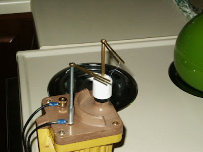
As a substitute system I have found a high voltage circuit using a car ignition coil online using a dimmer, capacitor, but no diode.  Here is a picture with a sizable spark.

Like Tesla's circuit, it works with 60 cycle power and no diode.  Here is the circuit diagram I have extracted as best as I can tell from the construction pictures.


So here we have a design more like Tesla's without the diodes, fulfilling the need of High voltage and possibly high frequency and noting that any coil automatically has capacitance.

  • Liked by
  • Augenblick
sampojoe posted this 02 May 2018

I have asked the question before:

Why does Don use Diodes on the Output?

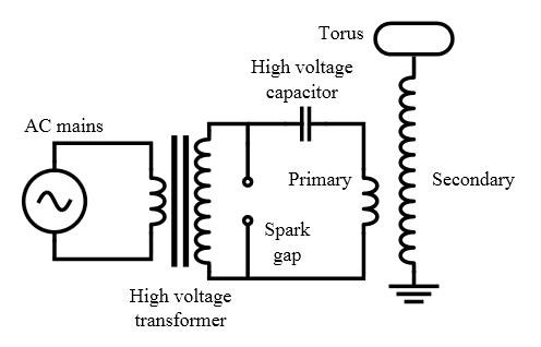
We know, for sure, the Input is a LC Resonant Spark Gap configuration, almost exactly like Nikola Tesla showed us 100 odd years ago:

Where, the 3 turn coil shown above is Dons L1 Coil which is 4 turns, and Don's Caps, 2 x 0.1 in parallel, is the Capacitor shown above, and the High voltage Neon Tube Transformer is the Step up transformer shown above.

Don's Secondary is completely different as we already know. Don's L2 Coil, as I have pointed out, is as described:

This is your L2 system, but its a double one, setup so that the Amps and Volts and everything are in there in the proper order.  This one I built in 1994.

Don Smith - /watch?v=W7GHqw7d1No&t=26m34s

   Chris


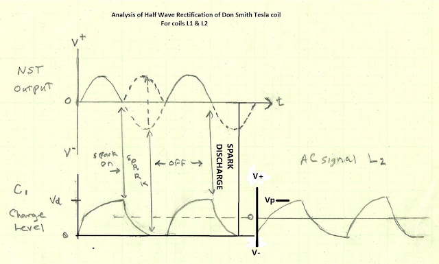
So lets take a stab at this post by Chris awhile back in conjunction with solving my L1 high voltage high frequency spark generation.  This question is the inverse of mine as I visualized how Don's rectified circuit might be made to generate an AC signal.  I think that a diode is required when developing high voltage for a SLOWER OUTPUT FREQUENCY  than the input, or when the input power takes several cycles to build sufficient charge for eventual discharge as when a HIGHER OUTPUT AMPERAGE is required on the output. Don may not have realized this, or its a distraction, but it seems Tesla understood it.  I believe the diodes are not needed at all for this application since the opposite requirements are the target in both cases.  So lets look at how this circuit may generate higher frequency.  The input voltage is a sine wave.  The spark gap is providing the frequency change, as long as once the minimum required voltage for discharge Vs is reached either at the positive or negative sides of the cycle, with the lower capacitance associated with the desired higher frequencies. So the higher the discharge rate the better, of course.  Here is a diagram to illustrate.

As Mman has recommended Tesla's circuit, so I have to wonder if he too has thought that a diode is not required and says as much when he stated that simpler is always better.

  • Liked by
  • Chris
  • Augenblick
Marathonman posted this 02 May 2018

The cap and coil in the Tesla circuit is an LC circuit which can be series or parallel.

And your assumption would be correct and that of the frequency also. remember the higher the frequency the larger the output thus your assumption about Don Smith. it may very well be just something he left out on purpose as he did with other information. what people don't realize Don was under contract with various entities thus could not divulge everything or suffer breach of contract.

i will leave you with this question and answer to ponder on, why do you think aircraft uses 400 hz and higher for military planes.? why does the size of the transformer change with higher frequency. 

power = square of the frequency.

Marathonman

  • Liked by
  • Augenblick
sampojoe posted this 02 May 2018

Thanks Mman.  My sine wave diagram posted previously then reveals the answer to my first question two posts back,

  • How can the "early device" we are trying to build actually be Don's 220 MHz Device, and operate at the 220 MHz frequency and not 35.1kHz?  
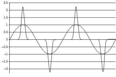
  • Answer: In the Sine wave cycle with the yellow bars, the yellow bars represent individual spark discharges.  Depending on the LC tuning, the frequency of the circuit that is of concern to this device is the spark rate contained with the  powering cycle sine wave. In Don's pictured device with diodes, it may be rectified, but in a Tesla device it is AC.  Thus the current in the Spark is flipping from plus to minus.  Does this matter to L2?  Not at all.  As I posted once before in this diagram, 

L1 loses all sense of polarity voltage when it transmits to L2.  Thus the circuit can be made to operate at a frequency much faster than an NST's 35.1kHz.  This is a red herring I have been chasing, to think this circuit operates around this frequency.  

And best of all, I have a hunch the spark gap drives the circuit automatically at its resonant frequency.

This should be set by the length of the L1 coil and capacitor in the circuit.  Hopefully at some point I can risk putting an oscilloscope on it to test my assumptions.  I will have to keep it operating under 2000v with a probe that I have.


  • Liked by
  • Chris
  • Augenblick
Zanzal posted this 02 May 2018

How can the Tesla device operate without a diode/capacitor circuit to build voltages for the spark gap (and provide a change to high frequency also)?

Greetings sampojoe,

I appreciate you are sharing your experiences here. I learn from them. I think the answer to your question (the frequency part) has to do with the wave form that can appear as the capacitor is charging and also discharging across the spark gap. Depending on how you configure your spark gap and capacitors the wave form at resonance can be a little unexpected. This simulation might give you an idea of what you could see when you are at resonance. Although I think the frequency shown in the simulator is a little on the absurd side (unmeasurably high). I've seen these when using GDTs at lower voltages. Perhaps someone has a better image they can post of this.

Spark Gap High Frequency

Oh and I'm not entirely sure about how the capacitor actually accumulates a net charge. Maybe its accumulating kinetic energy with oscillations growing larger and larger in response to continued input at regular intervals.. like pushing a swing at just the right time.

  • Liked by
  • Chris
  • Augenblick
Marathonman posted this 02 May 2018

sampojoe;

  The spark gap introduces all frequencies available to the system,  it is up to the R resistance, C capacitance, and L inductance of L1 that dictate the resonant frequency not the spark gap it's self.

This is explicitly shown in the Tesla circuit i shown you with the spark gap between the cap and L1 coil leaving the cap as the buffer, to say, to the 60 hz transformer.

the secondary can then be calculated at 1/4 wave length from that according to DS with automatic resonance. 

i hope this helps.


Marathonman

  • Liked by
  • sampojoe
  • Augenblick
Zanzal posted this 02 May 2018

This should be set by the length of the L1 coil and capacitor in the circuit.  Hopefully at some point I can risk putting an oscilloscope on it to test my assumptions.  I will have to keep it operating under 2000v with a probe that I have.

My cheapo-scope can often pick up wave forms if I place the probe near a capacitor or wire. It allows me to see the wave form without risking damage. The voltage will be wrong and there can be stability issues sometimes, but if you just want to see the waveform, it might work with yours.. Could be a feature of cheap design though.

  • Liked by
  • Chris
  • Augenblick
Chris posted this 02 May 2018

@Sampojoe,

In an LC resonant Circuit, with a Spark Gap, and knowing the average Spark duration is around the nano second range normally, and the Coil with the least resistance would see the largest discharge Current, would you say that it would be fair to estimate the current something like the following:

This very short, sharp pulse, Spark Discharge, a change in Magnetic Field, would do what to the output Coils?

   Chris


P.S: For the record, again, I still recommend learning this tech at high voltage is not a good idea, I don't recommend this. Low Voltages is a much batter idea. Experiment at your own risk.

sampojoe posted this 03 May 2018

With the dielectric of air running about 10000v per cm, with a very small gap of about 1mm, we may be able to observe operations around and maybe sllightly lower than 1000v.  

  • Liked by
  • Augenblick
Chris posted this 03 May 2018

It will raise the Voltage on the Output Coils, the Difference in Potential by a factor... Potential to now do work.

   Chris

  • Liked by
  • Augenblick
  • ISLab
Chris posted this 03 May 2018


Do we have any further perspective on the Diodes?

Why does Don Smith use Diodes on his Output Coils:


When the Diodes Conduct, and Current flows, what does this create?


   Chris

Jagau posted this 03 May 2018

Hi chris

See the attached document from Utkin, more precisely page 62 it explains very well what is the use of the 2 diodes at the output of 2 coils in buck mode.They create switchable inductance.

And with Tx quarter-wave balanced coil (L1C1) at resonance and the 2 Rx coils (L2C2) cut in half wave at the output and with the meeting point of the 2 coils to the ground this creates a receiving antenna which has a node in quarter wave.

Thus maximum current at the central nodal point, and maximum of voltage at the ends.

I realized what that Utkin proposes and I believe for a good understanding of Don Smith's project we should all try it. I work in low voltage for now to understand the effects.

Jack


Attached Files

sampojoe posted this 03 May 2018

Hi Chris,

I take the diodes on the output side to be the just the method Don has selected in his display model he used to begin the process of harvesting the ambient energy that has been captured by L2.  He has stated as much in his videos.  He shows an NST with 10000v potential running on a variac, so it is running at something less.  Aren't the caps on L1 5000v?  So again, something less than a 5000v operation may be indicated.  His spark arrestor component may top out around 2000v.  I haven't seen anything more on those.  So L1 may be operating around 2000v or less.  L2 is a step-up process of 4 times, or maybe around 8000v.  He has stated the system can put out 160kva, at 8000v.  The high voltage must be key to knocking loose the extra electrons i.e. current amplificaton, along with the nullification of Lenz's law with the opposing direction coils of L2.  So at the highest voltages on L2 must be transformed to something usable, but the 8000v cap bank is not the most practical method, but that is just the method Don has chosen to illustrate it on his display model.  And hence the diodes that do it on L2 are arbitrary also.

 Am I missing something from your knowledge and experience?  

In my modifications below, I am choosing to step down the voltage with a transformer first, and then rectify at voltages compatible with modern inverters available for solar panels.

However in the L1 circuit, I am now looking to drop the diodes (and the NST?).


  • Liked by
  • Augenblick
Marathonman posted this 03 May 2018

Thank you for sharing that information Jagau. lots of very valuable information.

Marathonman

  • Liked by
  • Chris
  • Augenblick
Chris posted this 03 May 2018

@Jack - Exactly! - This is exactly correct!

@All,

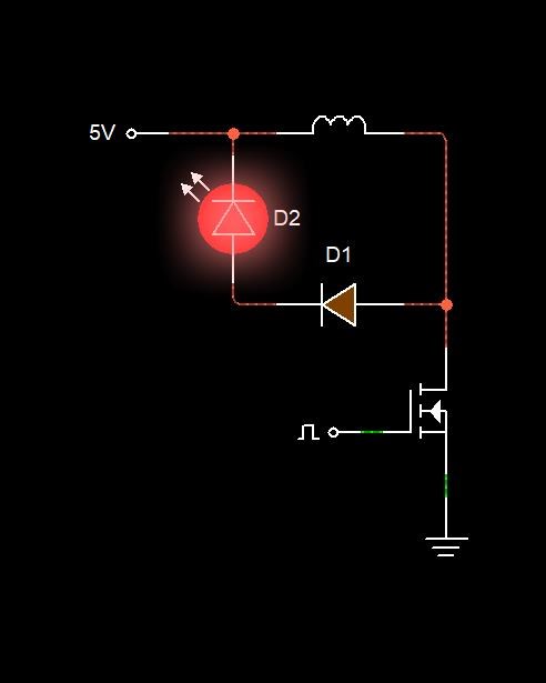
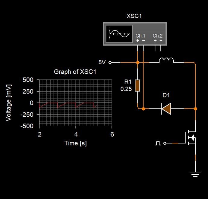
We are all familiar with the Bedini Works? Well, we have the oppertunity to capture Flyback, Inductive Collapse, or what ever term you wish to use. See the following diagrams:


The led Lights, the Current through a 0.25 Ohm Resistor is shown, but the Input is not the Action that creates this, not directly! The input, is Directly responsible for Creating a Magnetic Field!

The Coil wants to become a Source! An Active Element, or a Battery, but why?

  • The Mosfet apply's 5 Volts across the Coil.
  • The Coil creates a Magnetic Field as the Current through the Coil Ramps Up.
  • The Mosfet is switched Off.

What Happens Now:

  • The Magnetic Field Collapses.
  • The Magnetic Field Induces a Voltage on the Terminals of the Coil. Electromagnetic Induction!
  • The Voltage is the Potential for Current to Flow, and when the Coil is Loaded, Current Flows, as shown.  

As Jack points out, a Switchable inductance, the Coil becomes a Source! But only when the Diodes Conduct.

Note: As we have learnt, amplifying Current requires an Acceleration and a Liberation of Electrons! I have covered this in my Thread: Increasing the Rate of Kinetic Energy. Also, we have seen this in The Mr Preva Experiment

 I have also shown this in my Thread: Some Coils Buck and some Coils DONT


The Output Current is entirely dependant on the Voltage: I = V / R

   Chris

  • Liked by
  • Jagau
  • Augenblick
We're Light Years Ahead!
Members Online:

No one online at the moment


What is a Scalar:

In physics, scalars are physical quantities that are unaffected by changes to a vector space basis. Scalars are often accompanied by units of measurement, as in "10 cm". Examples of scalar quantities are mass, distance, charge, volume, time, speed, and the magnitude of physical vectors in general.

You need to forget the Non-Sense that some spout with out knowing the actual Definition of the word Scalar! Some people talk absolute Bull Sh*t!

The pressure P in the formula P = pgh, pgh is a scalar that tells you the amount of this squashing force per unit area in a fluid.

A Scalar, having both direction and magnitude, can be anything! The Magnetic Field, a Charge moving, yet some Numb Nuts think it means Magic Science!

Message from God:

Hello my children. This is Yahweh, the one true Lord. You have found creation's secret. Now share it peacefully with the world.

Ref: Message from God written inside the Human Genome

God be in my head, and in my thinking.

God be in my eyes, and in my looking.

God be in my mouth, and in my speaking.

Oh, God be in my heart, and in my understanding.

Your Support:

More than anything else, your contributions to this forum are most important! We are trying to actively get all visitors involved, but we do only have a few main contributors, which are very much appreciated! If you would like to see more pages with more detailed experiments and answers, perhaps a contribution of another type maybe possible:

PayPal De-Platformed me!

They REFUSE to tell me why!

We now use Wise!

Donate
Use E-Mail: Chris at aboveunity.com

The content I am sharing is not only unique, but is changing the world as we know it! Please Support Us!

Thank You So Much!

Weeks High Earners:
The great Nikola Tesla:

Ere many generations pass, our machinery will be driven by a power obtainable at any point of the universe. This idea is not novel. Men have been led to it long ago by instinct or reason. It has been expressed in many ways, and in many places, in the history of old and new. We find it in the delightful myth of Antheus, who drives power from the earth; we find it among the subtle speculations of one of your splendid mathematicians, and in many hints and statements of thinkers of the present time. Throughout space there is energy. Is this energy static or kinetic? If static, our hopes are in vain; if kinetic - and this we know it is for certain - then it is a mere question of time when men will succeed in attaching their machinery to the very wheelwork of nature.

Experiments With Alternate Currents Of High Potential And High Frequency (February 1892).

Close