Chris's Electromagnetic Charge Pump Experiment

  • Topic Is Sticky
  • 4.8K Views
  • Last Post 32 minutes ago
Chris posted this 04 November 2021

My Friends,

Some have spent 50+ years searching! We have what they could not find!

Some have Degrees, BA's, Ph.D.'s, all sorts of Education under their belt! Education, does not, by any means, mean: Smart!

Why have we succeeded, very simple, we have Open Minds, we have not aloud our minds to be clouded with Assumptions, or Postulates! We have found several simple things to be incomplete in Science, that they, their Exploration, failed to Find!

Their Symmetrical Mind Set has let them down!

You are all familiar with the following Circuit:


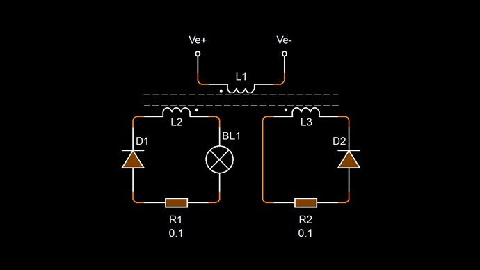
Well, we can do better! There is more!

Nikola Tesla gave us a phenomena of great importance when he filed Patent: No# 512,340

UNITED STATES PATENT OFFICE.
NIKOLA TESLA, OF NEW YORK, N. Y.

COIL FOR ELECTRO-MAGNETS.
SPECIFICATION forming part of Letters Patent No. 512,340, dated January 9, 1894.

Application filed July 7, 1893. Serial No. 479,804. (No model.)

To all whom it may concern:

Be it known that I, NIKOLA TESLA, a citizen of the United States, residing at New York, in the county and State of New York, have invented certain new and useful Improvements in Coils for Electro-Magnets and other Apparatus, of which the following is a specification, reference being had to the drawings accompanying and forming a part of the same.

In electric apparatus or systems in which alternating currents are employed the self-induction of the coils or conductors may, and, in fact, in many cases does operate disadvantageously by giving rise to false currents which often reduce what is known as the commercial efficiency of the apparatus composing the system or operate detrimentally in other respects. The effects of self-induction, above referred to, are known to be neutralized by proportioning to a proper degree the capacity of the circuit with relation to the self-induction and frequency of the currents. This has been accomplished heretofore by the use of condensers constructed and applied as separate instruments.

My present invention has for its object to avoid the employment of condensers which are expensive, cumbersome and difficult to maintain in perfect condition, and to so construct the coils themselves as to accomplish the same ultimate object.


I would here state that by the term coils I desire to include generally helices, solenoids, or, in fact, any conductor the different parts of which by the requirements of its application or use are brought into such relations with each other as to materially increase the self-induction.

I have found that in every coil there exists a certain relation between its self-induction and capacity that permits a current of given frequency and potential to pass through it with no other opposition than that of ohmic resistance, or, in other words, as though it possessed no self-induction. This is due to the mutual relations existing between the special character of the current and the self-induction and capacity of the coil, the latter quantity being just capable of neutralizing the self-induction for that frequency. It is well-known that the higher the frequency or potential difference of the current the smaller the capacity required to counteract the self-induction; hence, in any coil, however small the capacity, it may be sufficient for the purpose stated if the proper conditions in other respects be secured. In the ordinary coils the difference of potential between adjacent turns or spires is very small, so that while they are in a sense condensers, they possess but very small capacity and the relations between the two quantities, self-induction and capacity, are not such as under any ordinary conditions satisfy the requirements herein contemplated, because the capacity relatively to the self-induction is very small.

In order to attain my object and to properly increase the capacity of any given coil, I wind it in such way as to secure a greater difference of potential between its adjacent turns or convolutions, and since the energy stored in the coil—considering the latter as a condenser, is proportionate to the square of the potential difference between its adjacent convolutions, it is evident that I may in this way secure by a proper disposition of these convolutions a greatly increased capacity for a given increase in potential difference between the turns.


I have illustrated diagrammatically in the accompanying drawings the general nature of the plan which I adopt for carrying out this invention.

Figure 1 is a diagram of a coil wound in the ordinary manner. Fig. 2 is a diagram of a winding designed to secure the objects of my invention.

Let A, Fig. 1, designate any given coil the spires or convolutions of which are wound upon and insulated from each other. Let it be assumed that the terminals of this coil show a potential difference of one hundred volts, and that there are one thousand convolutions; then considering any two contiguous points on adjacent convolutions let it be assumed that there will exist between them a potential difference of one-tenth of a volt. If now, as shown in Fig. 2, a conductor B be wound parallel with the conductor A and insulated from it, and the end of A be connected with the starting point of B, the aggregate length of the two conductors being such that the assumed number of convolutions or turns is the same, viz., one thousand, then the potential difference between any two adjacent points in A and B will be fifty volts, and as the capacity effect is proportionate to the square of this difference, the energy stored in the coil as a whole will now be two hundred and fifty thousand as great. Following out this principle, I may wind any given coil either in whole or in part, not only in the specific manner herein illustrated, but in a great variety of ways, well-known in the art, so as to secure between adjacent convolutions such potential difference as will give the proper capacity to neutralize the self-induction for any given current that may be employed. Capacity secured in this particular way possesses an additional advantage in that it is evenly distributed, a consideration of the greatest importance in many cases, and the results, both as to efficiency and economy, are the more readily and easily obtained as the size of the coils, the potential difference, or frequency of the currents are increased.


Coils composed of independent strands or conductors wound side by side and connected in series are not in themselves new, and I do not regard a more detailed description of the same necessary. But heretofore, so far as I am aware, the objects in view have been essentially different from mine, and the results which I obtain even if an incident to such forms of winding have not been appreciated or taken advantage of.

In carrying out my invention it is to be observed that certain facts are well understood by those skilled in the art, viz.: the relations of capacity, self-induction, and the frequency and potential difference of the current. What capacity, therefore, in any given case it is desirable to obtain and what special winding will secure it, are readily determinable from the other factors which are known.

What I claim as my invention is—

1. A coil for electric apparatus the adjacent convolutions of which form parts of the circuit between which there exists a potential difference sufficient to secure in the coil a capacity capable of neutralizing its self-induction, as hereinbefore described.

2. A coil composed of contiguous or adjacent insulated conductors electrically connected in series and having a potential difference of such value as to give to the coil as a whole, a capacity sufficient to neutralize its self-induction, as set forth.

NIKOLA TESLA.

Witnesses:
ROBT. F. GAYLORD,
PARKER W. PAGE.


The Coefficient of Coupling of Coils / Inductors ( K ) is a unique variable. If the Factor is equal to 1, then the Coupling is considered Unity Coupling. Normally, Unity Coupling is where one Inductor is on top, directly, of the other. In other words, no Space is separating the Inductors/Coils.

Here is one way to Visualise this:

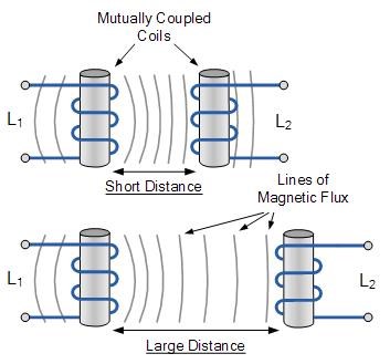
Ref: Mutual Inductance


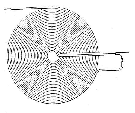
Here, a Transformer with Unity Coupling:

Both input and output Coils are considered Unity Coupled, Inner Coil is the Primary and Outer Coil is normally the Secondary.

Basically, Electromagnetic induction is better, the closer you have the Coils to the Source Changing Magnetic Field!


NOTE: The Natural state of two Parallel Wires, if Current Flows, is in Opposite Directions! I have stated this Here. NOT in the Same Direction:


Most all of us here, already know this stuff, all have either learnt this prior to becoming a member, or from prior posts on this Forum.

In Practice, if we use what we have learned already, we can, in point of fact, use this knowledge, to gain an advantage.


Nikola Tesla says:

What I claim as my invention is—

  1. A coil for electric apparatus the adjacent convolutions of which form parts of the circuit between which there exists a potential difference sufficient to secure in the coil a capacity capable of neutralizing its self-induction, as hereinbefore described.

  2. A coil composed of contiguous or adjacent insulated conductors electrically connected in series and having a potential difference of such value as to give to the coil as a whole, a capacity sufficient to neutralize its self-induction, as set forth.


I propose the opposite, to Maximise the Self Induction.


My Friends, a recap for you:


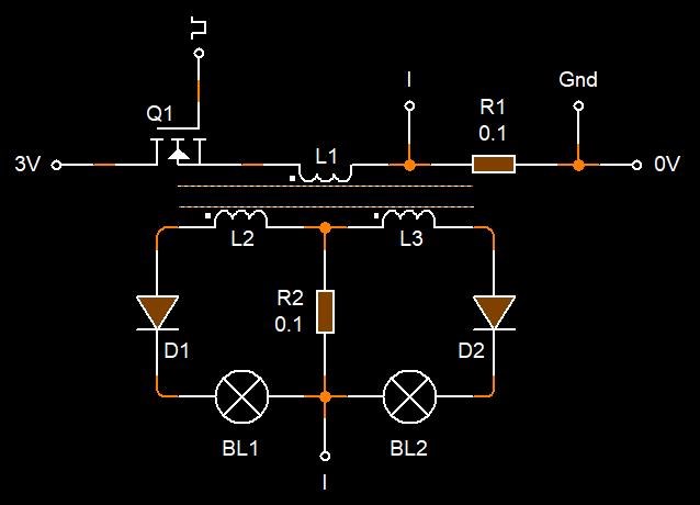
We can have a Bi-polar Version:
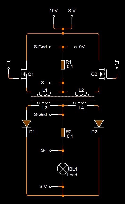
 

Where:

  • S-Gnd = Scope Ground.
  • S-V = Scope Voltage Probe.
  • S-I = Scope Current Probe.


The Bi-Polar Version is a bit more difficult to use, and operate! The DC Pulses must be set, both Frequency and in Duty Cycle spot on to make this work efficiently.

NOTE: A Capacitor on the Output, is a good idea! The Capacitor will make for easier Measurement and also Spike Smoothing. Helping to protect your Scope and Equipment!

This probably should be a requirement at this stage!


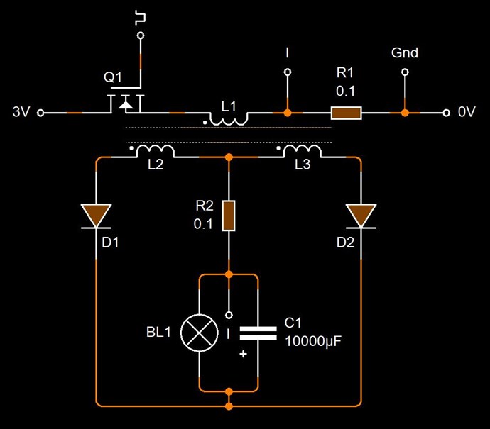
NOTE: C1 the 10,000.00 uF Capacitor. This will absorb the Spikes and Smooth the Voltage and Current Spikes we saw in earlier experiments. I know most here know this already, but for those that don't.

The input Coil must fit the Partnered output Coil Resonance Frequency. What I mean, the Slope of the Current on the input Coil, must match the Slope of the Voltage on the Output Coil when at Resonance.

NOTE: I urge all here, a refresher on: Reduced Impedance Effect. This is an Important Effect!

I present a small demonstration, designed to show Effects Only:

I have decided to put this Video into a Series of Videos, here is Part One:


I do not wish to debate Measurements, I know what's possible, and this is merely a simple demonstration to show what's possible. Most of you, here, know what's possible already! This is simply the start! Step two of many!

Remember, Current I = Voltage V / Resistance R, so if Voltage V increases, Current I must also Increase! Ohms Law is our Friend!

This original thread can be viewed here: https://www.aboveunity.com/thread/one-step-ahead/ which will be modified later on.

Best Wishes,

   Chris

Order By: Standard | Newest | Votes
Chris posted this 21 December 2021

My Friends,

The Easiest Inception of a New Technology is in its Simplest Form!

There are two problems with this statement:

  1. What one Individual understands as Simple, is not necessarily what another Individual Understands as Simple!
  2. A Base Level of Understanding, is required, to Understand the Technology, in the First Place!


Ironically, all of the most Functional Energy Machines that History has Shown Humanity, are Electromagnetic in Nature and this particular Field is riddled with Contradiction, Inconsistencies and unbelievable Naivety, toward the Education of this Subject!

Most Physics Classes do NOT Teach the True and Correct Operational Properties of the Conventional Transformer! Some do these days and this subject is slowly starting to correct its Fabricated Inconsistencies!

I have given what I believed to be the Easiest Inception of this Technology:


Many took on this task and many Succeeded! Some did not, Simply Because, they did not take the time to learn what is REQUIRED to make this machine work! They did not take the Time to Learn!

The Key is:

  1. Bucking Coils
  2. Magnetic Resonance
  3. Understand these Phenomena!


Chris's Non-Inductive Coil ExperimentIS, The Easiest Inception of this New Technology in its Simplest Form! However, this is only the start, this is very much more board and extensive!

Taking the time to learn about a simple Inductor:


Does not give any clues to how more than one Inductor can Interact together in Complex Action Sets.

Action Sets: 1, 2 and 3, or: Action, Reaction and Counter-Reaction, the True Newtonian Physics that has always been Hidden from Humanity!

Asymmetrical Newtonian Physics


NOTE: Asymmetrical Newtonian Physics also consists of Symmetrical Newtonian Physics, one cannot apply without the other, but only in one direction! E.G: Symmetry, does not require Asymmetry, Asymmetry does however, require Symmetry! Isn't this amazing!

Symmetry is a Subset of Asymmetry! See why Science is Incomplete!


Why does this work like a Pump?

The Copper Atom has 29 Electrons. Elementary Charge is based on the Electron. All Elementary Charge has three Fundamental Properties:

  • Mass
  • Charge, and thus a Magnetic moment.
  • Spin


The Charge, and thus a Magnetic moment, makes the Elementary Charge susceptible to External Magnetic Fields, and thus, Elementary Charge can be made to move within the Insulated Conductor, creating an Electromagnetic Charge Pump:


I have referred to this experiment:


NOTE: I hope members do not mind, I have removed some posts to try to keep the will to Experiment Alive and keep a Healthy Direction! 

Best Wishes,

   Chris

Chris posted this 15 December 2022

My Friends

The Magnetomotive Force is seen here:


And again here:


Slowing the Velocity of the Magnet!

This Force, it is NOT Lenz's Law, it is Amperes Force Law: FM = μ0 * I1 * l / 2π * r

Best Wishes,

   Chris

Chris posted this 17 March 2023

My Friends,

At what point does POCOne ( L2 ) have the same Magnetic Field Density ( B ) and Strength ( H ) as POCTwo ( L3 ) ?


Where is this ideal Point found?

I have given you all the answer to this, some time back, but not many have read that thread!

At this point, your Input Coil see's No Load, wow how amazing is that! Do you see this amazing fact, its possible, and taken me many years to figure out, but possible to calculate this! I have a means to verify my machines for the most part and its all within the Conventional Science Envelope, but so many people never bothered to look harder!


The Dumb Dumb Club will be furious, hearing such a thing is possible, and its not in their textbooks!!! Chricky Mates, what Blasphemy!!!

Best Wishes,

   Chris

ISLab posted this 19 March 2023

Hi Chris,

First of all, let me express my deep gratitude for all that you have done and are doing. I have read through many of the threads multiple times while doing the experiments and have understoods things more deeply each time. I can now better appreciate why you insist of everyone gettings hands on with the coils -- there truly is no replacement for experimentation as existing EM theory is so limited and our minds have been so biased to think only in terms of symmetry.

The content you offer and the entire explanation of the working of POC to generate OU is so simple and clear. There are still some gaps in my understanding of the implementation which I hope to fill as I move further with the experiments.


At what point does POCOne ( L2 ) have the same Magnetic Field Density ( B ) and Strength ( H ) as POCTwo ( L3 ) ?

Where is this ideal Point found?

From what I have understood so far:

  1. Changing current on L1, dI1/dt induces V2 on L2. This pumps I2 on L2, which as dI2/dt induces V3 on L3. As V3 pumps I3 the magnetic field (proportional to I3) begins to rise, although initially lagging behind I2.
  2. When L1 cuts off, the V2 on L2 begins to drop, leading to drop in I2. Meanwhile I3 was still rising. The two (L2 and L3) now meet at some point just after L1 has cut off where both currents (and therefore magnetic fields) are of same intensity.
  3. In case of delayed conduction on L2 and L3, the current I2 switches on later, but rises more rapidly with higher dI2/dt inducing higher V3 and higher I3. The difference in this case would be that both I2 and I3 rise to higher values and also meet at higher levels. But still the meeting point is just after L1 cuts off.

Please comment and correct.

Chris posted this 19 March 2023

Hey ISLab,

Yes, reading your post, and reading between the lines a little, yes you're correct.

We need to think in terms of L2 and L3 or POCOne and POCTwo each have a Voltage ( V ) and each have a Current ( I ).

Each Voltage and each Current in these Coils must be 180 Degrees out of phase and approximately equal in Magnitude. This is Magnetic Resonance!

At this point, each POC is Generating the others Voltage, and thus each POC being opposite, Pumps each Others Current, over time: di / dt.

The Generation of Voltage is the very Important part, because as Voltage is Generated, we can have a Current flow, with little to no Voltage, we have little to no Current, you get the idea.

Thus, an Asymmetrical Electromagnetic Induction System, one of the First the World has ever seen!

EDIT: Without L3 or POCTwo working in an Assistive Mode, we do not have Asymmetrical Electromagnetic Induction! This is the Important part!

Best Wishes,

   Chris

thaelin posted this 23 March 2023

Hope this is not off topic here but as I see this, L1 does not trigger L2 but does l3. When L3 breaks down, it triggers l2. When L2 breaks, it triggers L3 again but at a bit lesser level. This continues until the magnetic force is drained out. At that point, L1 again fires and starts this all over.  L2 and L3 "must" be of equal value so to perpetuate the slow drain off and pumping of the current.  

   This whole setup has ragged on me for a long time. Hope I am finally getting a handle on how it is to work. If I am just puluting the topic, then Chis, plz do delete this. I have an open order for a amcc0400 core and #16 wire soon. I have to make this work or else it will beat me for ever. 

Chris posted this 23 March 2023

Hi Thay,

Yes there is a Feed Forward and Feed Back all at the same time.

Floyd Sweet Wrote:

The feedback loop: Previously mentioned, you will more clearly see how the loop functions at the time you see the physical construction of the stationary armature of stator assembly. The underlying principal (forget Millikan’s experiment) has been derived in that magnetic effects vary on the square of the current. As the load on the machine increases, the volt-ampere product increases. The rate of flow of charges increases. Quantum mechanics state not all electrons in copper are free to carry charges. Then it’s time to set the wheels in motion to free them from binding magnetic forces. Once this is done, conductivity will improve and resistance decrease as we are dealing only with electrons. Copper will not change to another metal as atoms which are mostly empty space would have many electrons to spare anyway. To free enough electrons to effect conversion would require magnetic forces approaching infinity.

An illustration will help to clarify how the feedback principal counters the magnetic force binding the electrons in orbits, restraining them from motion as charged particles in the form of an electric current.

Ref: The Space-Flux Coupled Alternator Floyd Sweet

Best Wishes,

   Chris

Chris posted this 02 May 2023

My Friends,

Because Electromagnetic Induction works:


And because we are smart enough to understand the issues with Electromagnetic Induction, and therefore solve the issues, we can build Energy Machines that produce an excess of Energy Output, well Above the Unity Boundary!


All while the Energy Community are so damn dumb, they cant even navigate their way out of a Paper Bag!

Best Wishes,

   Chris

Chris posted this 22 hours ago

My Friends,

I have said I would share more, well, today I am showing you more, something amazing, something we have not seen before, something that was reported by Floyd Sweet in his early machines! Today is a BIG Share, this is the start to our Future!

The effect is specifically related to Partnered Output Coils!

Here: Floyd Sweets Lab Notes, you will see:


There are several References to the 400Hz machine. Floyd worked hard to change the Frequency, he was aiming for 60Hz.

I have asked others to look for the effects, the same effects we have seen those before us achieve, well today, I am going to show you an effect that will change the world forever:


Please NOTE: I miss-spoke when I said there is no link from Input to Output! There is a link and Lenz's Law does apply for a short instant at the start of the pulse. There is a disconnect because at low frequency we have no flashing of the globe.

At the heart of this machine, we are dealing with a Charge Pump!


Where:

  • Yellow is Input Voltage.
  • Teal is input Current.
  • Pink is Output Voltage One.
  • Purple is Output Voltage Two.


This experiment is not AU, but maybe soon we might show you the AU Version.

NOTE: At Low Frequency, we should see a Pulsing on the Globe, Brighter, as at Low Frequency, the Highest Current flows through the Input Coils, and in a normal Electromagnetic Induction Case, we would see a much Brighter flashing on the globe, not a dimming!

The Dimming at low Frequency shows there is something very different going on here!

Best Wishes,

   Chris

  • Liked by
  • Plasmonic
  • FringeIdeas
FringeIdeas posted this 17 hours ago

Great video!

I have seen that, more than once. And I'll be honest, I brushed it off as a bad probe or scope issues. I had not thought to check the load or input. But I will now when I see that again. 

Few ideas come to mind, but I'll be quiet for now because I don't know. But it does look like something is gaining momentum. Super interesting, now that you point it out. Thank you for the video!

Marcel

  • Liked by
  • Chris
  • Plasmonic
Chris posted this 17 hours ago

Hey Marcel,

I had a feeling many of you would have seen this effect!

Fact that the Bulb does not Flash Brightly at Low Frequency, this is important and shows we have Electromagnetic Induction occurring that is Different than the Symmetrical Electromagnetic Induction we all know. So, in other words, if our Input was Directly, and Symmetrically responsible for the Induction Cycle, then we would not see the effects shown, the Bulb would flash brightly at low frequency.

This means, and we can see, there is Electromagnetic Induction occurring between POCOne and POCTwo directly, because we have each Coil Right Hand Grip Rule Opposing, but wired as Floyd Sweet describes:


FIELD SUPER-POSITION AND THE VACUUM TRIODE

Electromagnetic induction with no measurable magnetic field is not new. It is well known that in the space surrounding a properly wound toroidal coil there is no magnetic field. This is due to the superposition of the fields. However, when alternating current is surging through a transformer an electric field surrounds it. When we apply the principle of superposition to the vacuum triode it becomes more obvious how the device is in fact operating.

The principle of superposition states that; "In order to calculate the resultant intensity of superimposed fields, each field must be dealt with individually as though the other were not present". The resultant is obtained by vector addition of each field considered singularly.


Consider for a moment the construction of the triode which includes the bifilar coils...

When the current in one half of the conductors in the coils (i.e., one of the bifilar elements in each coil) of the device is moving up, both the current and the magnetic field follow the right-hand rule.

The resultant motional E-field would be vertical to both and inwardly directed.

At the same time the current in the other half of the conductors in the coils is moving down and both the current and magnetic field follow the right-hand rule.

The resulting motional E-field is again vertical to both and inwardly directed.


Thus, the resultant field intensity is double the intensity attributable to either one of the set of coil conductors taken singularly.

Expressed mathematically: E = (B x V ) + ( -B x -V ) = 2 ( B x V )


You will note: E = (B x V ) + ( -B x -V ) = 2 ( B x V ) is this statement, in long form:


Quote


If the directions of the two signals are such that opposite H-fields cancel and E-fields add, an apparently steady E-field will be created. The energy density of the fields remain as calculated above, but the value of the E-field will double from E / 2 to E.


The Equation shows us this: E = (B x V ) + ( -B x -V ) = 2 ( B x V ) and the reason we see the rise in Amplitude is the slow "Generation" of E.M.F through the Opposing M.M.F's. This very same Opposing of M.M.F's Pumps the Current.

Instantly turn off one M.M.F, then the Current instantly is gone also. So, the Opposing of M.M.F's not only Frees Charge, but it also Accelerates Charge down the wire. This experiment is proof that we can Generate exactly as Floyd Sweet described, its true and real, exactly as he stated and no one ever decided to further investigate this!

Oh dear, the other Forums have SO very much to learn! 

Best Wishes,

   Chris

  • Liked by
  • FringeIdeas
  • Plasmonic
Chris posted this 32 minutes ago

My Friends,

Most of you know how the Coils are configured already:

My Friends,

Here is a small sneak peak of what's coming:

You all should be able to see the similarity to Floyd Sweets VTA, at least for the most part:


What are the differences? 

  1. I have a Cross Sectional Area that uses almost the entire Magnet Face, 100mm x 150mm x 12.5mm
  2. and no doubt you see the rest...


Don't forget, by now it should be drilled in:


Knowing: Voltage is "Generated", and a Current is Pumped! The Pumping is done using the Bucking of the Coils!

We are Light Years Ahead of the Other Forums! They have no idea what so ever!

Best Wishes,

   Chris


Don't forget what Steven Mark said:


The scope shots show something that is quite unusual! Very little to no Trace below the Zero Graticule Line:

My Friends,

I have said I would share more, well, today I am showing you more, something amazing, something we have not seen before, something that was reported by Floyd Sweet in his early machines! Today is a BIG Share, this is the start to our Future!

The effect is specifically related to Partnered Output Coils!

Here: Floyd Sweets Lab Notes, you will see:


There are several References to the 400Hz machine. Floyd worked hard to change the Frequency, he was aiming for 60Hz.

I have asked others to look for the effects, the same effects we have seen those before us achieve, well today, I am going to show you an effect that will change the world forever:


Please NOTE: I miss-spoke when I said there is no link from Input to Output! There is a link and Lenz's Law does apply for a short instant at the start of the pulse. There is a disconnect because at low frequency we have no flashing of the globe.

At the heart of this machine, we are dealing with a Charge Pump!


Where:

  • Yellow is Input Voltage.
  • Teal is input Current.
  • Pink is Output Voltage One.
  • Purple is Output Voltage Two.


This experiment is not AU, but maybe soon we might show you the AU Version.

NOTE: At Low Frequency, we should see a Pulsing on the Globe, Brighter, as at Low Frequency, the Highest Current flows through the Input Coils, and in a normal Electromagnetic Induction Case, we would see a much Brighter flashing on the globe, not a dimming!

The Dimming at low Frequency shows there is something very different going on here!

Best Wishes,

   Chris


As you all know, we would normally see some Below Zero Tracing but we don't, very little, its 99.999% Positive Tracing.

Its also very unusual to see the Trace go Higher, after the Switch off of the Input.

What we are seeing here is very unusual, very different, and this needs to be studied by all here! I cant do it all.

Best Wishes,

   Chris

We're Light Years Ahead!
Members Online:

No one online at the moment


Past Visitors: 0 | Live Visitors: 0


3D globe widget by: Chris Sykes

What is a Scalar:

In physics, scalars are physical quantities that are unaffected by changes to a vector space basis. Scalars are often accompanied by units of measurement, as in "10 cm". Examples of scalar quantities are mass, distance, charge, volume, time, speed, and the magnitude of physical vectors in general.

You need to forget the Non-Sense that some spout with out knowing the actual Definition of the word Scalar! Some people talk absolute Bull Sh*t!

The pressure P in the formula P = pgh, pgh is a scalar that tells you the amount of this squashing force per unit area in a fluid.

A Scalar, having both direction and magnitude, can be anything! The Magnetic Field, a Charge moving, yet some Numb Nuts think it means Magic Science!

Message from God:

Hello my children. This is Yahweh, the one true Lord. You have found creation's secret. Now share it peacefully with the world.

Ref: Message from God written inside the Human Genome

God be in my head, and in my thinking.

God be in my eyes, and in my looking.

God be in my mouth, and in my speaking.

Oh, God be in my heart, and in my understanding.

We love and trust in our Lord, Jesus Christ of Nazareth!

Your Support:

More than anything else, your contributions to this forum are most important! We are trying to actively get all visitors involved, but we do only have a few main contributors, which are very much appreciated! If you would like to see more pages with more detailed experiments and answers, perhaps a contribution of another type maybe possible:

PayPal De-Platformed me!

They REFUSE to tell me why!

We now use Wise!

Donate
Use E-Mail: Chris at aboveunity.com

The content I am sharing is not only unique, but is changing the world as we know it! Please Support Us!

Thank You So Much!

Weeks High Earners:
The great Nikola Tesla:
N. Tesla

Ere many generations pass, our machinery will be driven by a power obtainable at any point of the universe. This idea is not novel. Men have been led to it long ago by instinct or reason. It has been expressed in many ways, and in many places, in the history of old and new. We find it in the delightful myth of Antheus, who drives power from the earth; we find it among the subtle speculations of one of your splendid mathematicians, and in many hints and statements of thinkers of the present time. Throughout space there is energy. Is this energy static or kinetic? If static, our hopes are in vain; if kinetic - and this we know it is for certain - then it is a mere question of time when men will succeed in attaching their machinery to the very wheelwork of nature.

Experiments With Alternate Currents Of High Potential And High Frequency (February 1892).

Close