Chris's Non-Inductive Coil Experiment

  • Topic Is Sticky
  • 34K Views
  • Last Post 13 February 2025
Chris posted this 08 October 2019

My Friends,

I am going to show a small experiment, one that follows the works of Andrey Melnichenko and even Tariel Kapanadze's works and as we know many others.
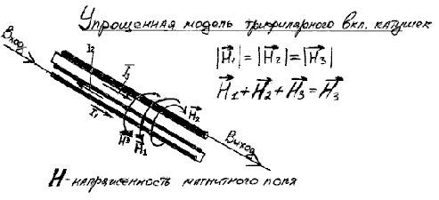


We have discussed here before, the fact that H3 is H3 simply because H1 and H2 cancel out: H1 + H2 + H3 = H3, why is this so, because H1 is Positive and H2 is Negative! We have seen this equation before: 1 + -1 + 1 = 1.

I think with Fighter's success recently, its time for some hands on!

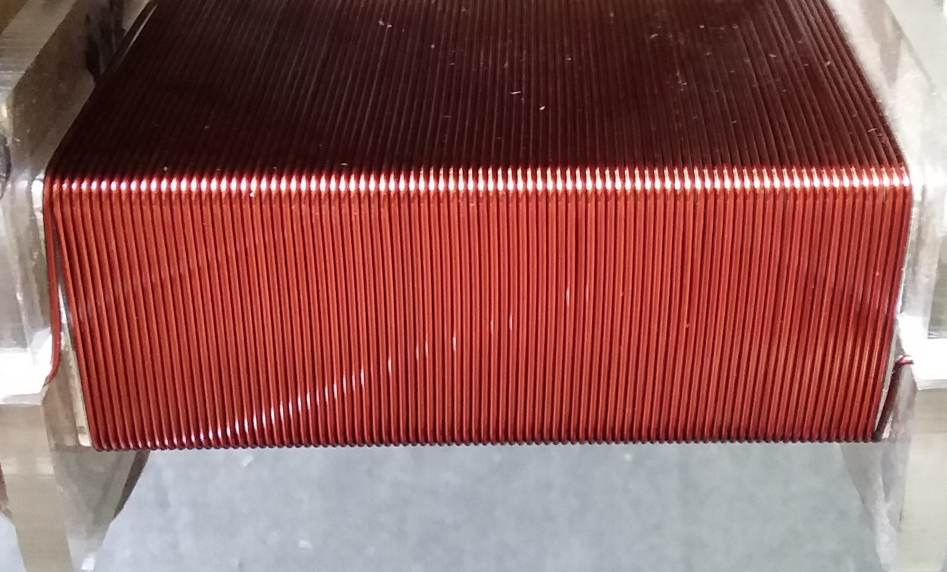
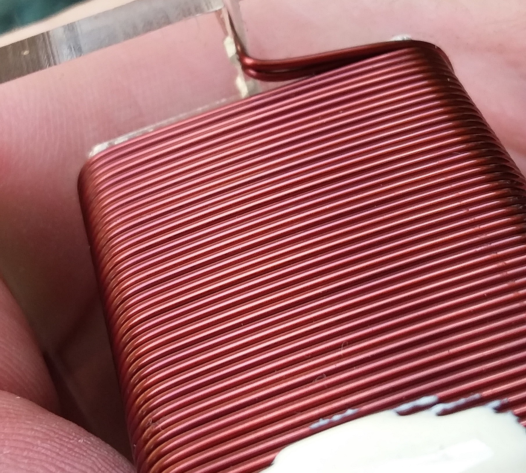
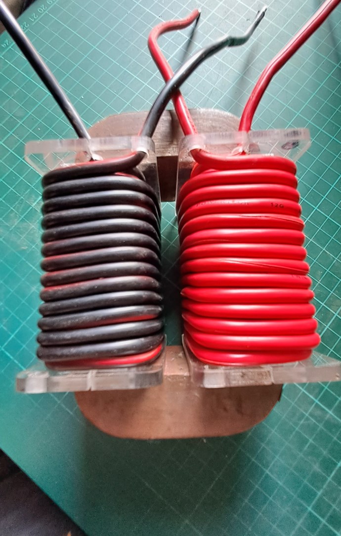
  • First Layer: 88 Turns.
  • Second Layer: 43 Turns.


Layer One:


Layer Two:
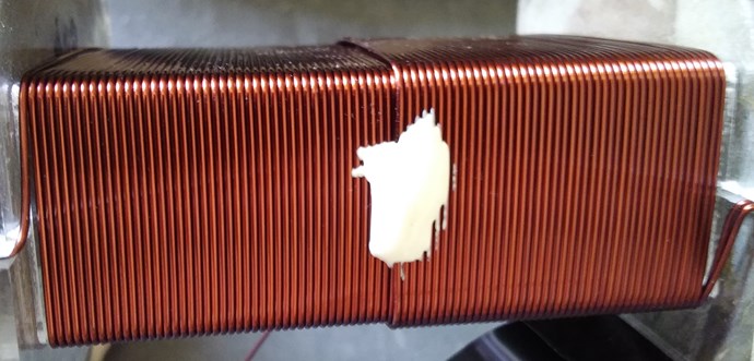
 

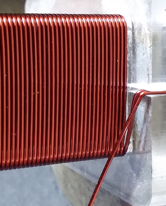
Turns Direction:
 

Layer One Inductance:
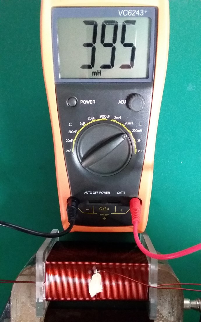
 

Layer Two Inductance:
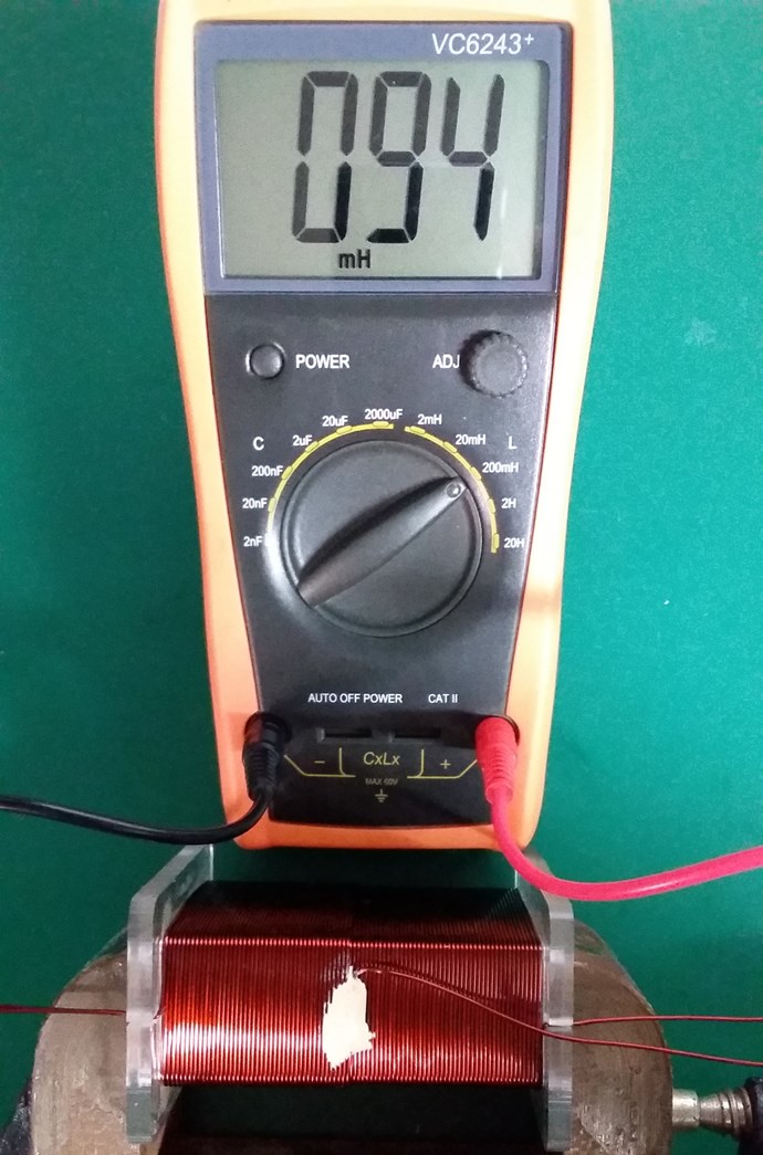
 

Non-Inductive Connected:
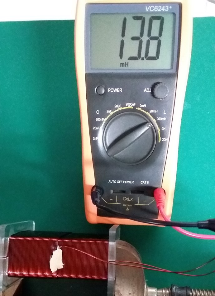
 

Layer One Resistance:
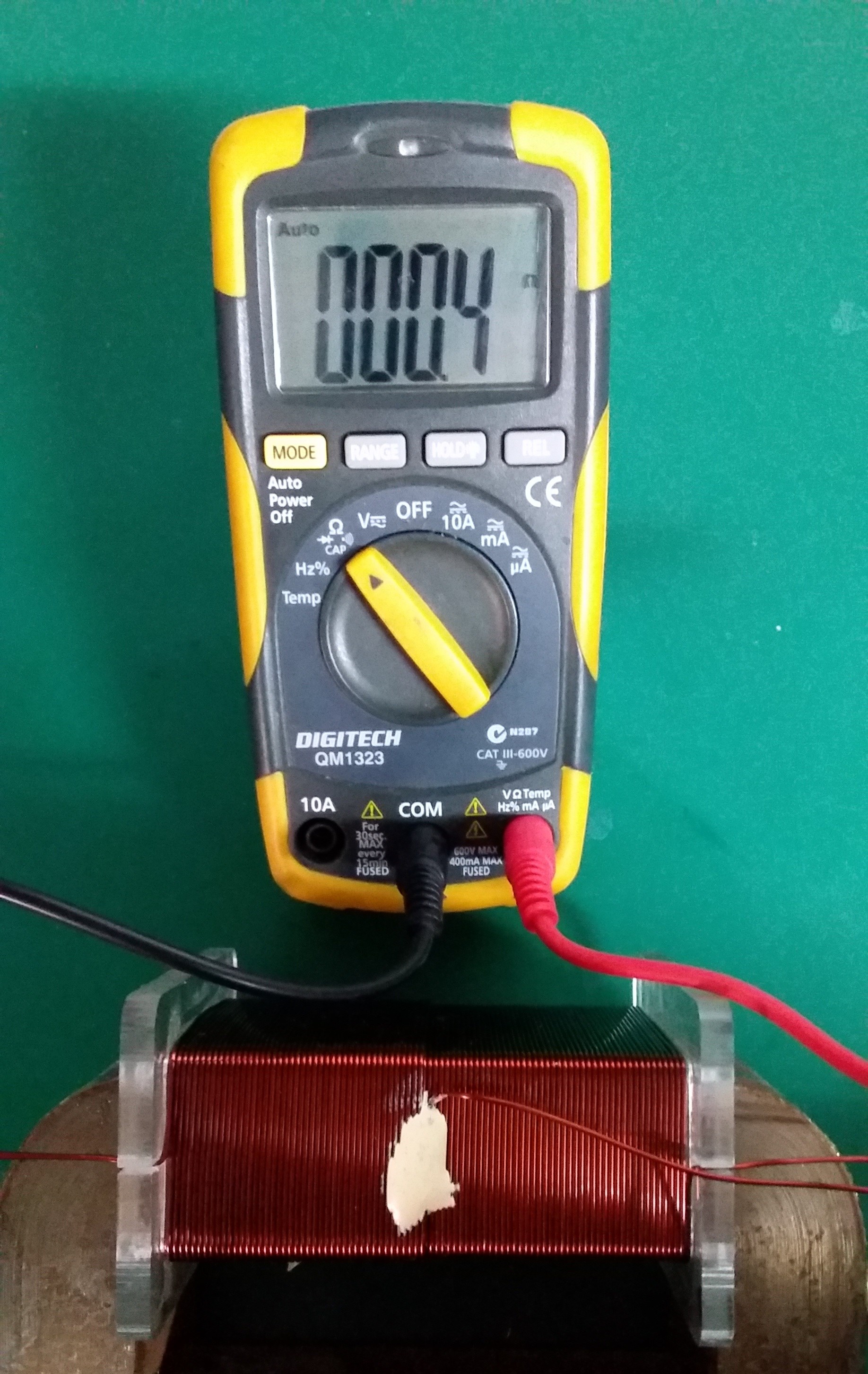
 

Layer Two Resistance:
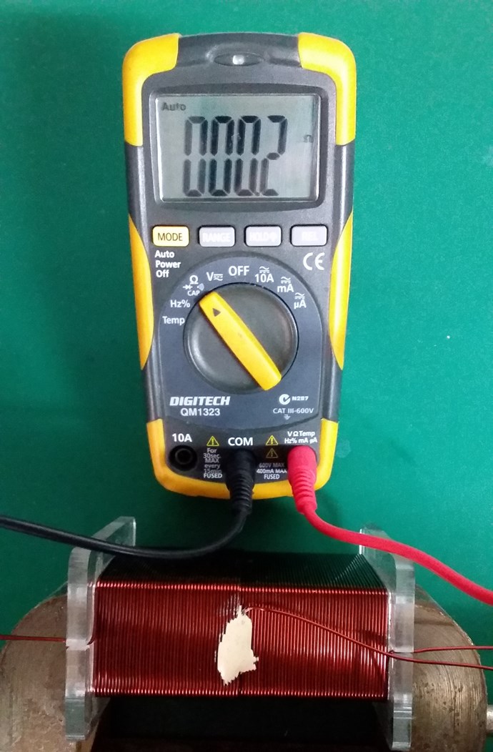
 

Closed Loop Resistance:
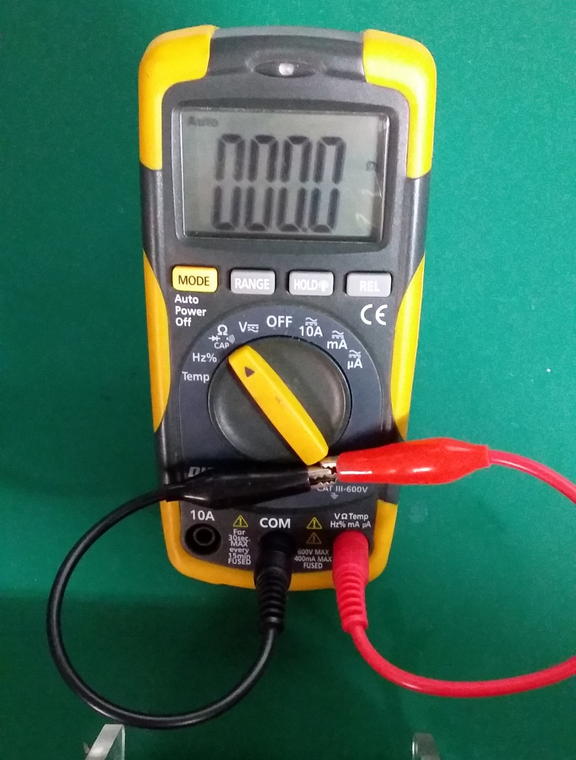
 

My Coil, like Andrey Melnichenko's, is 0.33 + -0.33 + 0.33 = 0.33.

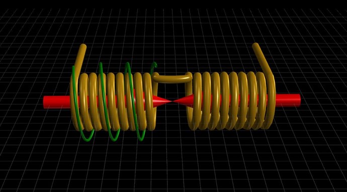
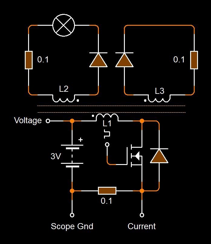
Two thirds of my Coil is canceled out. My Circuit looking like this:
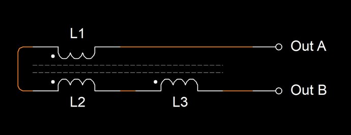
Where:

  • L1 and L2 are Non Inductive.
  • L3 is Inductive.


If this Coil is carrying 1 Ampere of Current, and exactly one half of the Coil is Non-Inductive, then Turn for Turn, only 45 Turns will create an M.M.F, which is considered as 45 Turns x 1 Ampere = 45 Ampere Turns or 45At.

Science tells us, that Turn for Turn, where we have Non-Inductive part of the Coil, this part of the Coil does nothing! Creates no Magnetic Field, therefore does nothing.

However, from Experiment, we know that this part of the Coil DOES do something! Remember Floyd Sweets paper: Nothing is Something, this is the same!

At Resonance, we have a perfect Standing Wave! We know this as Magnetic Resonance! Where each Magnetic Field is 180 Degrees out of phase:
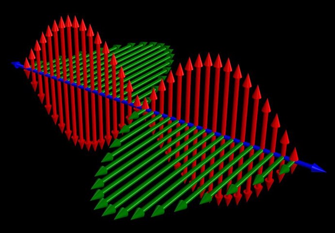
 

Now, straight away, we should see a problem! Why? Kirchhoff's Current Law says the Current must be equal at every node, but we have Turn for Turn, one Coil that is Inductively Zero, and another Coil that has only a part of the Induction canceled!

In the specific case of positive charges moving to the right and negative charges to the left, the effect of both actions is positive charge moving to the right. Current to the right is:

I = da+ / dt + da- / dt

Negative electrons flowing to the left contribute to the current flowing to the right.


Each node does not equal the other, so the Circuit must balance out, Current is Increased as the Standing wave shows us.

Remember what Induction is? See here: Non-Linear Inductance

Induction gives us an approximation on the Coils ability to carry a Current: L = ε / di / dt

By Bringing a Coil arrangement like this into Resonance is our task.

Where each Electromagnetic Wave travels in opposite directions. One through the other in the same space.

THE NATURE OF SPACE

Space itself is the ability to accommodate energy. Consider for a moment the following illustration:

A signal (energy) is transmitted from point A to point B. A and B are separated by a finite distance. Consider three periods of time:

  • The signal is launched from A.
  • 2) The signal resides in the space between A and B.
  • 3) The signal arrives at B.

If (3) occurs simultaneously with (1) we say that the signal has traveled at infinite velocity. The signal has never resided in the intervening space and therefore there exists no space between A and B. A is virtually at the same point in space as B. For real space to exist between A and B it is necessary that a signal travelling between them be "lost" with reference to both points for a finite period of time.

Now we know that for real space to exist between two points a signal travelling between them will propagate at a finite velocity c, ( c = 1 / √με )

If a signal will not travel between two points, as in the case when c = 0, then we can also conclude that there is no link or intervening space between them. 

Ref: Floyd Sweet - Nothing is Something.


Floyd Sweet tried very hard to make c = 0! What does this mean? It is simply a Standing Wave, a Team Wave was used:

It is a simple matter using the equations E / H = √με and c = 1 / √με for a team wave to get rid of H and c and so convert the first equation into the well known equation for energy density in the so-called electrostatic field.

Ref: Floyd Sweet - Nothing is Something.


I have pointed out: Why 'C' is equal to One in these Devices.

We have a lot of data!

   Chris

Order By: Standard | Newest | Votes
Chris posted this 31 August 2022

My Friends,

Jagau is correct! This small motor shows some very simple Magnetic Concepts!

Magnetomotive Force, M.M.F is the same as Magnetic Field Strength, H, except the difference is:

H = M.M.F / l

  • H = Magnetic Field Strength measured in Amperes per metre (Am-1).
  • M.M.F = Magnetomotive Force measured in Ampere turns (At).
  • l = average length of Magnetic circuit measured in metres (m).


A larger M.M.F will naturally produce a stronger field. This is shown in the last posts, as Amperes Force Law, and we went through some calculations, please check to make sure they are correct, that Faradays Law requires Unit Magnetic Field Density B:

B = I / A .

  • B = Flux density measured in Webers per metre squared (Wm-2).
  • I = Magnetic Flux measured in Webers (W).
  • A = Cross sectional area perpendicular to the field lines measured in metres squared (m2) .


Now, the Magnetic Field Strength, H, is never covered in Faradays Law and is never touched upon in Physics as being associated in the same domain as Faradays Law, but I can prove, via some math and experimentally, that the Magnetic Field Strength is a very important factor in this quest of Energy Density ε.

Soon I will be showing a device that immediately you will see all the necessary concepts to improve my Output, this I have already given in the thread Coil Geometry and here on this Thread.

If you want to have Energy to Power your Home and make it Free, its very easy! I have given you all the answers! All in the threads on this Website!

Best Wishes,

   Chris


P.S: there are so many Idiots that cant navigate their way out of a Paper Bag, so please do not, ever, follow or pay any attention to them! They are idiots and will always be idiots!

Chris posted this 21 September 2022

My Friends,

I had to have a giggle at this:

Ref: Holcomb and other FE technology debate


Do you see what we are dealing with?

Proof is in the work you put in yourself to make these machines work, some never will!

Do you think F6FLT has ever done an experiment along the lines of this:


Only one member of that forum ever tried to replicate, and they stopped at, I believe, a 1.6% drop in Input Power before they made sense of what was going on, and achieved the goal!

NOTE: 90% Input Power Drop is very easy to achieve with a bit of work:

My Friends, you need to do this for your selves, no one is ever going to do this for you! I will help you! Members here will help you!


There is NO ENERGY Crisis, its a manufactured strategic plan that they are applying.

Focus on the facts, and observe the small things:


Aboveunity.com is the only forum in the world with Answers!

Best Wishes,

   Chris
  • Liked by
  • strape
  • Augenblick
Chris posted this 22 September 2022
My Friends,

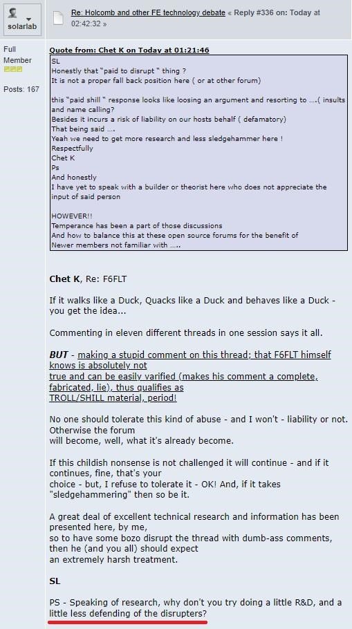
This is a prime example of why we Ban the Trouble Makers:

Ref: Holcomb and other FE technology debate


Oh My, what trouble Other forums have! 

Best Wishes,

   Chris

  • Liked by
  • Augenblick
Chris posted this 22 September 2022

My Friends,

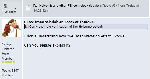
I saw a post today, and I think this should become a topic of discussion, perhaps 20-30 or so years ago it should have been prioritized as a primary prerequisite? Hay that sounds a bit logical doesn't it!

Here is the post:

Ref: Holcomb and other FE technology debate 


My Friends, this is a very simple solution!


Example

An Electric Generator is 95% Efficient, Torque Energy is equal to the Electrical Output Energy minus Losses!

We have a method to reduce Shaft Drag by 80% for the same Electrical Output, simply by off setting the Magnetic Force, or MMF, imposed on the Rotor, in the form of Shaft Drag, and still have the same: ΔΦB / Δt which is the Magnetic Field Density Changing in time.

This is very easy to achieve! "Generator" Shaft Drag is entirely M.M.F related, meaning, the "Generated" E.M.F is present with Shaft Drag of only:

  • Bearing Friction Loss
  • Windage Loss
  • Inertial Loss


However, if one loads the Output, and a Current Flows, a Secondary Magnetic Field is then present, apart from the Source Magnetic Field, we have an extra Loss:

  • Magnetic Drag Loss, or MMF Damping


Which is the most significant Loss of all, I have shown this in this video:


It is very important to study and understand Electromagnetic Induction, as this IS Energy "Generation" which Powers your Lights and so on!

In the above Video, there is one: v x B or E.M.F, in the single Copper Conductor which has a Magnetic Field that Changes in Time in Phase, remember: Floyd Sweet told us, we need 2 v x B to make this work!

This means the question posed in the above quoted post is a very poor question to be asking after a few decades of Research!

Best Wishes,

   Chris

ansen posted this 07 October 2022

Hi Chris,

So I understand that you use an H-bridge to drive your primary coil. And I know that it's also possible to just do simple switching with a transistor, but do you have a circuit diagram or guide on how you built your H-bridge?

Regards,

ansen

Chris posted this 07 October 2022

Hi Ansen,

Yes, on the Forum we have many links to Resources: Reliable and Flexible Switching System

You will see this on the Website:


Switching System is where you will find the PCB and data.

NOTE: I use a single Chanel Mosfet, not in H-Bridge Mode, to Drive My Input Coil! Please see Circuit Diagrams on this Thread.

Best Wishes,

   Chris

Chris posted this 13 December 2022

My Friends,

If you want Free Energy Machines, the answer is right here, in this Thread!!!

Are you paying attention?

Best Wishes,

   Chris

Chris posted this 18 January 2023

My Friends,

Truth of the matter is: "Those ignoring the technology in this thread are either: Dumb or Ignorant"

Do the math:


Independent Replication = Scientific Proof and choosing to stay ignorant when the Answers are right in front of your eyes is stupidity!

Why do so many 'supposed' researchers choose to stay ignorant to the most simple, cheapest, Free Energy Machines ever! The reason is, they are not Genuine Researchers, they are Paid Disinformation Artists!

This thread gives you all the data you need to Succeed!

Best Wishes,

   Chris

Chris posted this 22 January 2023

My Friends,

Finally people are starting to get it! What I have been sharing for a very long time now, is starting to sink in and become Understood:


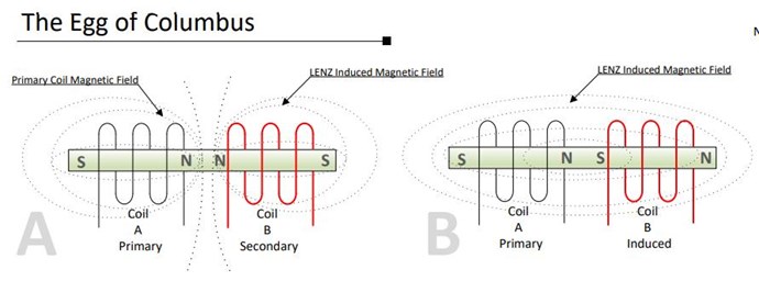
The Egg of Columbus


NOTES:
One of the most fundamental physical laws is known as Lenz’s law, which states that a changing
magnetic flux causes an induced voltage. The resulting current creates a magnetic field that opposes
the magnetic field that created it. Lenz’s Law will always exist in every two coil arrangement.
It is foolish to believe anyone can prevent this natural effect from occurring. Drawing A and B identify
how magnetic fields interact in a typical transformer/generator circuit. In Drawing A, magnetic fields
are compressing each other. In Drawing B magnetic fields are complementing each other.
In the absence of Lenz’s Law, the magnetic field would produce potential energy without, or having
done very little work. This configuration would violate law of conservation of energy. This is evidence
enough to understand a two coil arrangement does not, and can’t produce extraordinary results.

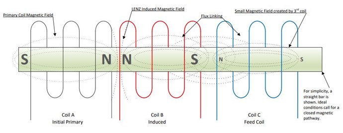
Coil A can be 120 or 220 volts (or any primary voltage you desire). Drawing above identifies one specific moment when Coil A induces a
magnetic field in Coil B. Coil B magnetic field is LENZ induced. Coil B North Pole opposes Coil A North Pole. LENZ also creates a South Magnetic
Pole, and this South magnetic pole is feed energy through a low power magnetic field generated by Coil C. In the ideal design, Coil C voltage
matches Coil A Primary Voltage.
It is important to understand that Coil C cannot be energized before Coil A. If Coil C is energized before Coil A then Coil C will be subjected to
LENZ forces, and will be the driver of Lenz in Coil B. However, the stronger Coil A magnetic field, when energized, will quickly distort the
magnetic field in Coil B when Coil C initiates Lenz. When Coil C is energized, AFTER a LENZ generated magnetic field in Coil B, due in whole to
Coil A, then Coil C is not impacted by LENZ, or influences Coil B through Lenz, but feeds energy, through its magnetic field to Coil B.
In the drawing, Magnetic Poles of Coil C are shown as smaller letters. This implies that this magnetic field must always be smaller then the
induced field. If Coil C generated a larger magnetic field, then Coil C magnetic field would have too great of an influence on Coil B, and Coil B
field would distort. 

There is no Free Energy

Is it a myth and only fools believe they will generate Free Energy from
High Voltage. Power is only produced through interaction of magnetic
fields. There is nothing free, power is always required to generate power.
COP < 1 is produced with two interacting magnetic fields, as seen in a
simple generator design. COP > 1 is always produced through the
interaction of three magnetic fields. COP > 1 should not be confused with
Free Energy. Free Energy implies that the power generated came at no
cost. COP > 1 requires that energy is utilized to produce results greater
than the typical outcome. The math, when calculated correctly will
identify that energy is conserved, or no laws are violated.
A large magnetic field will always influence a smaller magnetic field, and
can change the pole configuration or distort the smaller magnetic field.
Coil C should never be more powerful then the induced magnetic field.
The magnetic energy from Coil C will flow unimpeded due to Lenz’s
already having been developed from the Primary Coil A. Coil C magnetic
field growth must be delayed, or in other words, Coil B magnetic field
must develop first through Lenz before Coil C is fired off. Essentially there
is no direct Lenz relationship between Coil C and Coil B.
No complex electronics are required. A toroid coil is sufficient and AC
voltage on the primary coil should be used. If AC 120 Volts is used for the
Primary then AC 120 volts will be the output at a combined increased
power output. A 220 volt AC input will also produce a 220 AC output. A
feedback coil (feedback oscillator) can be used to drive Coil C.
Happy Experimenting.

Ref: Re-Inventing The Wheel-Part1-Clemente_Figuera-THE INFINITE ENERGY MACHINE


Member Hannon, posted the pdf attached to the bottom of this post.

His thinking is on the right track! However, the author of this document is not entirely correct in his thinking and diagrams! There are errors! When does B occur and how can this be used? Is Image Two correct?

Best Wishes,

   Chris

Attached Files

Melendor posted this 27 January 2023


His thinking is on the right track! However, the author of this document is not entirely correct in his thinking and diagrams! There are errors! When does B occur and how can this be used? Is Image Two correct?

Best Wishes,

   Chris


Hello Chris.
I can try to bring a little light on the errors if I may:

Image A is correct if Coil B is loaded...Opposing magnetic fields , because of Lenz's Law.
Image B , I find it not correct , because if 2 magnetic fields are in the same direction with 0 opposition..there is no Lenz Law.
In image C , as I can tell Both Coil B and C , are firing a N poles towards the input Coil.They are both opposing the Input.
Hope I got it right..

Good Job everybody.
Keep up the good work.
~~~ Melendor the Wizard

Chris posted this 27 January 2023

Hey Melendor,

Yes you're correct.

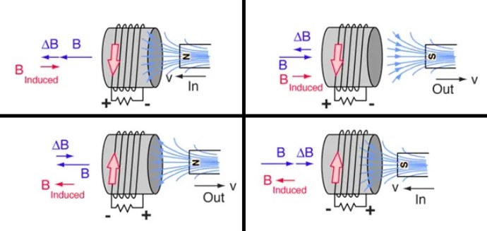
Science tries to teach us this is how Faradays Law, with Lenz in the equation as the Negative Sign: E.M.F = - dΦB / dt, works! And for the most part, it is correct:


The Velocity V of the Magnetic Field is Indicated. The Induced Magnetic Field B is also Indicated BInduced.

As discussed, POCOne and POCTwo are entirely bound by Electromagnetic Induction Laws, Voltage is Induced by the Change in Magnetic Field B.


However, do we see this in our Experiment? Can a Diode reverse Polarity Mid DC Cycle?

Best Wishes,

   Chris

Chris posted this 03 February 2023

My Friends,

I will just leave this here:


Best Wishes,

   Chris

donovan posted this 03 February 2023

Hi,

Is that a Metglas core and HV wire?

Donovan

PS, I keep studying all the material here......so much good information.....so many experiments to try......to reinforce the theory...

Chris posted this 03 February 2023

Hi Donovan,

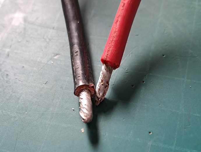
Metglas core yes,  and HV wire no, high current. I think from memory 12 Gauge multi strand.

More coming soon, we need to build on our knowledge as a team, and then we all benefit. I will pose a few more pictures today.

Best Wishes,

   Chris


Chris posted this 04 February 2023

My Friends,

Please Note: This is the exact same setup as I have already Presented on this thread, that's why its on this thread!

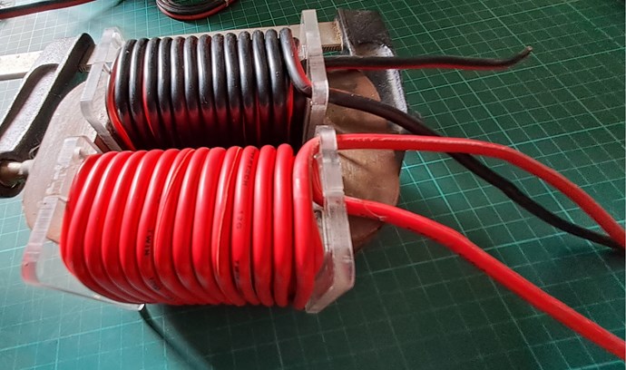
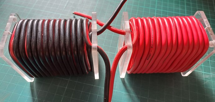
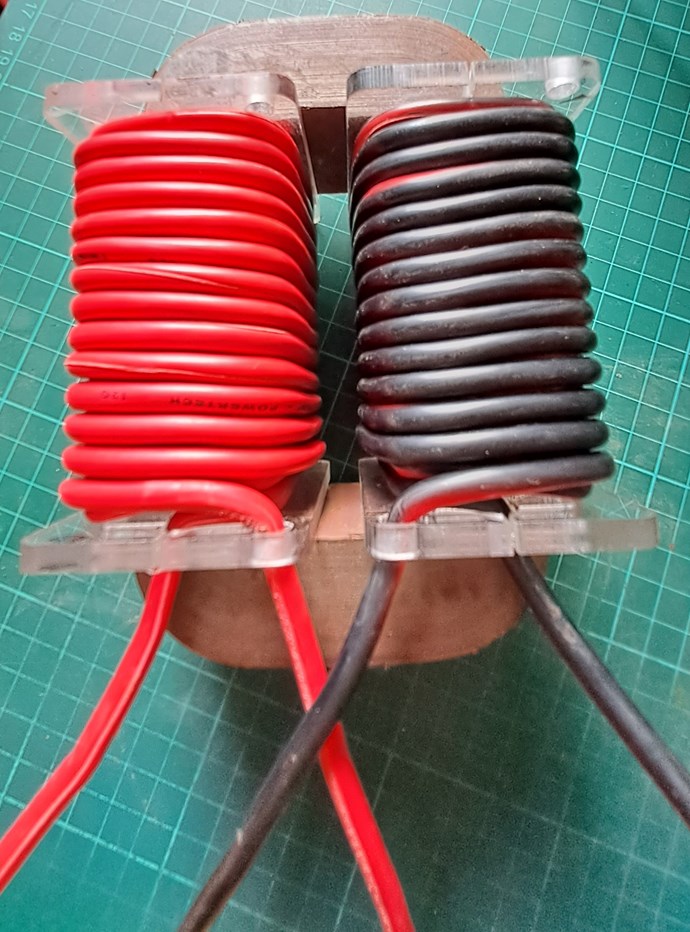
As promised, some more images:


Here, you can see, very clearly, the parallel:


Some more:


Mr Plagiarist 💯! aka Mr 'Brainless Buffoon Boy', will not understand a single thing here, but everyone else will, you can see a Parallel that only study and learning can give, why we wind the Coils like this, why we have each Coil Opposing, mostly not yet shown in these experiments, but shown on this and other pages, but you will see, its coming, in time, and soon you will see how I am going to Drive, or Excite the Coils, to get Useful Power Output!

EDIT: Ohhhhh, Poor Little Buffoon Boy is having a moment... Oh dear how sad never mind!

I just cant believe how far behind the Other Forums are! We are Light Years Ahead of the other Forums!

Best Wishes,

   Chris

donovan posted this 04 February 2023

Hi,

It is so exciting to be a part of this......I hope I can be a productive and worthwhile contributor....

Donovan

Chris posted this 04 February 2023

Hey Donovan,

Everyone that has viewed this information, some for many years now, is becoming a contributor, weather they like it or not. Some Negative, but most Positive!

At the moment I will keep this experiment a Useful Toy, but lets see which way this heads... 

Thank You!

Best Wishes,

   Chris

Chris posted this 09 February 2023

My Friends,

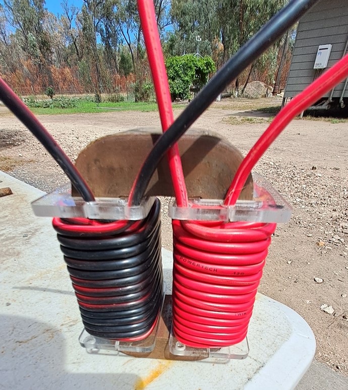
On the Outside of this Coil arrangement:


If I were to wind a Seven Turn Coil, and drive this Coil with an H-Bridge, what sort of behaviour should I expect from the Black and Red Partnered Output Coils?

NOTE: the Simplicity!

Its pretty straightforward and very cheap to run a few simple experiments.

Best Wishes,

   Chris

donovan posted this 09 February 2023

Hi,

Some, bucking opposed magnetic energies.

Donovan

Chris posted this 09 February 2023

Hey Donovan,

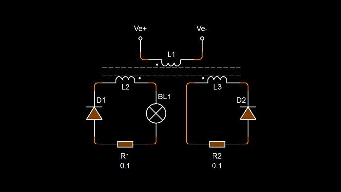
Yes, if I add Diodes, and we have, as part of this experiment, then POCOne and POCTwo will Oppose, they will Buck!

Shown Here.

and combine the two, into a slightly different Circuit:


Of course, this way, we can Tune the Partnered Output Coils, using our H-Bridge, to find Magnetic Resonance, which is where we find Currents approximately Equal in Amplitude, and Opposite. Where we have Maximum Bucking occurring in our Closed Core, Magnetic Loop!

I cant believe how many Clueless Researchers there are out on the Other Forums!


We are LIGHT YEARS Ahead of the Other Forums!


Best Wishes,

   Chris

Chris posted this 17 June 2023

My Friends,

Interesting, YouTube removed my comments on this video:


Why were my comments removed? Because they are Censoring Me!

Energy is so simple! Stress in the Magnetic Field, Charge Separation! 

Best Wishes,

   Chris

Chris posted this 22 June 2023

My Friends,

So many Posts I read over on Other Forums, they continue to show their Mouths are bigger than their brains, and their brains are pretty much firing on 2 neurons, which is a joke! Especially when you consider the Human Brain has in the order of over 100 Billion!

Experiment proves Fact, and Independent Replication is industry standard, because repeatability is proof! Fact is, aboveunity.com is the First, and Only place you will find Real Working Energy Machines!!! All the others are Fake! Especially over at BeyondPlagiarism.org!!!


Independent Replication is Scientific Proof:


Proof, and the Dumb Dumb Club cant see the Forest for the Trees! When too many Idiots flood the Forums, they make a mockery of the Truth! Right here, it's been here for nearly a Decade, you can SEE The Truth:


Start Here → Builders Guide to Aboveunity Machines

There are two mistakes along the way to Mastery: Not Starting and and not going all the way!

Cite: Master Shi Heng Yi

On rare occasions, Sweet saw this effect, called self-oscillation, occur in electric transformers

Ref: http://merlib.org/node/5282

The Answers you seek are right here:


I have provided 11 videos on this showing you how to approach this Technology! I have given you all of the data to make this work, and more, to make this, not just a TOY, to make this Power very much more than just a few Globes!

My Friends, when I see 10 successful replications, I will release another Video showing a bit more work, again we have had quite a few successful replications already! Do the Math in these videos! COP > 1.6 in both Machines!

Tinman was the first:


Others followed, like Captainloz:


Others also, some may not want their names used? Security for people is important to me, but eventually, we must do this as a Team and make a Stand!


We have Self-Running Machines, Our Flashlight that a Member of AboveUnity.com has achieved:


Aboveunity.com is Light Years Ahead of the other Forums!

Lighting up the Darkness!!!


There are a lot of very, very stupid idiots out there, they try to lead you!!! Don't be Led, be your own Leader! Don't follow Idiots!

There is only One Truth!

Aboveunity.com is Light Years Ahead of the other Forums!

Lighting up the Darkness!!!


Best Wishes,

   Chris

Chris posted this 04 July 2023

My Friends,

All Researchers should be Pragmatic:

dealing with things sensibly and realistically in a way that is based on practical rather than theoretical considerations. "a pragmatic approach to business ethics"


Success will follow if Researchers follow this approach, as those before us have, and succeeded!


Independent Replication is Scientific Proof:


Proof, and the Dumb Dumb Club cant see the Forest for the Trees! When too many Idiots flood the Forums, they make a mockery of the Truth! Right here, it's been here for nearly a Decade, you can SEE The Truth:


Start Here → Builders Guide to Aboveunity Machines

There are two mistakes along the way to Mastery: Not Starting and and not going all the way!

Cite: Master Shi Heng Yi

On rare occasions, Sweet saw this effect, called self-oscillation, occur in electric transformers

Ref: http://merlib.org/node/5282

The Answers you seek are right here:


I have provided 11 videos on this showing you how to approach this Technology! I have given you all of the data to make this work, and more, to make this, not just a TOY, to make this Power very much more than just a few Globes!

My Friends, when I see 10 successful replications, I will release another Video showing a bit more work, again we have had quite a few successful replications already! Do the Math in these videos! COP > 1.6 in both Machines!

Tinman was the first:


Others followed, like Captainloz:


Others also, some may not want their names used? Security for people is important to me, but eventually, we must do this as a Team and make a Stand!


We have Self-Running Machines, Our Flashlight that a Member of AboveUnity.com has achieved:


Aboveunity.com is Light Years Ahead of the other Forums!

Lighting up the Darkness!!!


Fact is: Not many Researchers are Pragmatic! Most are irrational and illogical!!!

There is only One Truth!

Aboveunity.com is Light Years Ahead of the other Forums!

Lighting up the Darkness!!!


Best Wishes,

   Chris

Gucio posted this 08 June 2024

I would like to follow you in this experiment to better understand what we are dealing with. I built a simple single-channel control system and a system of measurement blocks according to Chris.
Is a ferrite core from a TV suitable for observing this phenomenon?

I have such a ferrite core, will it be good?


Grzegorz

Chris posted this 08 June 2024

Hey Gucio,

Yes, all experiments are valuable! I did a lot of early experiments with small ferrite core, and I learnt a lot.


There are lots of limitations when working with small cores, and Electrodynamics requires a Cross Sectional Area (CSA) in the equations to "Generate" a Voltage.

Floyd Sweet also said:

Now let us consider the losses. Copper or I2R losses remain but may be minimized by using wire of larger than usual cross-sectional area.


Coil Length is also Important! See Coil Geometry for more details.

What I have shared works, we have many independent replications showing various levels of results! It works! Its Simple! 

Best Wishes,

   Chris

Chris posted this 02 October 2024

My Friends,

Here is a small sneak peak of what's coming:


You all should be able to see the similarity to Floyd Sweets VTA, at least for the most part:


What are the differences? 

  1. I have a Cross Sectional Area that uses almost the entire Magnet Face, 100mm x 150mm x 12.5mm
  2. and no doubt you see the rest...


Don't forget, by now it should be drilled in:


Knowing: Voltage is "Generated", and a Current is Pumped! The Pumping is done using the Bucking of the Coils!

We are Light Years Ahead of the Other Forums! They have no idea what so ever!

Best Wishes,

   Chris

FringeIdeas posted this 06 October 2024

Chris, curiosity is getting the best of me.

What are these sections of the former designed for?

And if you don't mind sharing at this point, what are the plans for the input coil(s)? Orientation, etc.?

Thanks, beautiful build so far btw.

Marcel

Chris posted this 06 October 2024

Hey Marcel,

The holes are for the threading of Wire from the terminals ( Holes ), really just an access hole, if needed.

I am trying to work a bit smarter, adding into, at design time, the things that will help at later stages. Terminals, where the holes are will make for a much easier terminating of the ends of the Coils when it comes to Hookup and so on.

Best Wishes,

   Chris 

Adam posted this 12 October 2024

Hey Chris,

This is just my total speculation and guess on how Floyd Sweets VTA works or the principles behind it. Not sure how close I am to the correct answer but take a look. My hole theory works on moving (with very low input) the Bloch wall that all magnets have in the center of them or maybe something similar to this.


What do you think?

Have fun

Adam.

Chris posted this 12 October 2024

Hey Adam,

Yes, for the most part, I agree with your theory.

Yes, the Image I shared here, shows a small gap in the middle, shown again here:


Floyd Sweets Drive Coils were at 90 degrees to the Power Coils, so yes, the Magnetic Field must have had to have induced a Voltage in these coils to keep the VTA in Operation:


I never caught Walt in a Lie! Ever! He was a good, genuine man that had a lot of pressure to stay quiet, in my opinion.

After decades of experiments and work, costing massive amount of time and money, I believe the evidence shows, we have for the most part, Cracked the case of the VTA, and what I have given freely, is a part of the answer to the resurrection of Floyds Sweets VTA for the world to Benefit from!

Best Wishes,

   Chris

Adam posted this 13 October 2024

Chris,

I agree, if you hadn’t been so generous to all of us and freely released all the information you have not very many people would know about bucking coil configurations and the bloch wall that magnets have.

Most people would still be working in circles from misinformation. Lol

The people on this forum should be very grateful to you as this is probably the only chance they will ever have to understand how real free energy is made !


Thank you for sharing your experiments and knowledge, I know it takes a lot of time, money, and frustration. You are the only person I have ever herd of that has ever given away as much information as you have. You should be proud of yourself and the work you have done.


Thanks again


Adam.

ISLab posted this 13 October 2024

This is just my total speculation and guess on how Floyd Sweets VTA works or the principles behind it. Not sure how close I am to the correct answer but take a look. My hole theory works on moving (with very low input) the Bloch wall that all magnets have in the center of them or maybe something similar to this.

.................................

What do you think?

Have fun

Adam.

Wow! This is so clear now with your images. Suddenly the whole importance of the Bloch Wall and several other posts of Chris now make so much more sense. As also this one which I only recently discovered.

Thank you Adam!


Chris,

I agree, if you hadn’t been so generous to all of us and freely released all the information you have not very many people would know about bucking coil configurations and the bloch wall that magnets have.

Most people would still be working in circles from misinformation. Lol

The people on this forum should be very grateful to you as this is probably the only chance they will ever have to understand how real free energy is made !

Thank you for sharing your experiments and knowledge, I know it takes a lot of time, money, and frustration. You are the only person I have ever herd of that has ever given away as much information as you have. You should be proud of yourself and the work you have done.

Thanks again

Adam.

I wholeheartedly second that!

Nicola Tesla was the first to fully share his knowledge through his patents (at least in the ones that are still available publicly), but he did not explain the science behind the amplication of current, etc.

Chris Sykes is the first and only one to have explained the entire theory, and also to have given out the simplest means for implementation using DC-pulsed POC.

Without his clear explanation of the theory and the application, we would have been wandering around in circles for decades more!

Thank you again Chris! 🙏🌞😇

Bird_eye posted this 13 October 2024

I am living out of my country due to the conditions of work life and responsibilities, 
I believe,
when exploring something it is important to make carefully connections in between what you found on the path.
I beleive,
This path should cross from T.Bearden, DSmith,Kapanadze e.t.c.
The field of magnet is the example of self sustained system ,
it has stationary waves locked in time,  when externally you modulate it 
you will get this waves are shifted in time thats all,

So it is familiar what Adam is posted, thanks for posting, i beleive it has more parameter than it seems,

Strong magnet field can be achieved on any coil when form standing waves at resonance this is similar with stationary field of magnet, are you able to prove that standing waves are formed on your coil?How?

Thats why having of standing waves and delayed conduction is the prarameter of the system,

T.Bearden talks about dipole protection by using different ground path, do you know practical sample of it? How is possible achieve it during the cycle?

Chris talks about 90 degree input coil orientation, and the document many time ago i shared it tells same,  does it make sense? How?

These are already talked at some degree in this form,
But indivually Baerndorfer's and CaptinLoz's study was always shows difference by adapting this parameters and physical result,


P.S. Source of energy is not POC coil or something else, it is just movement of particles has mass at atomic level , thank you for voltage and current is just part of same coin and electron movement is not diminishing and continue at eternal state, 

Regards,
Bird_Eye

Alex ⋐˙⋮⋮˙⊃ posted this 13 October 2024

Hi team,

first of all, thank you all for sharing everything so openly, especially for someone like me who just 1 year ago, didn't know what a full bridge rectifier actually is.

The people on this forum should be very grateful to you as this is probably the only chance they will ever have to understand how real free energy is made !

I second that as well 🙌


Speaking to this image:


Below we have the most iconic coffee stain in human history 😁
Would you guys assume/know if the Power coils (P1 and P2) actually require this "nested bifilar" coil configuration ? 


It would make so much sense that P1 and P2 are like Walt Rosenthal said, because below is a picture where Floyd Sweet with a magnet against a CRT screen, something that Chris also replicated.
Bi-toroidal or hyperbola shape:


Thanks for everything,
Alex


Chris posted this 13 October 2024

Thank You Guys and Gals,

You're too kind!

Yes, you are all on the path to make this work just as Floyd Sweet had this working! Its all about "Generating" Power Asymmetrically, ensuring your Input is not the Prime Mover, and M.M.F Balance between the Partnered Output Coils is as close to the same as possible. When this occurs, your Input will go right down or even sometimes negative.

Floyd Sweet wrote:

E = B x V + -B x -V = 2 B x V


Andrey Melnichenko wrote:

H1 + H2 + H3 = H3


I prefer:

M.M.FPrimary + M.M.FPOCOne + M.M.FPOCTwo = M.M.FPrimary


MMF is easier to understand, in my opinion.

As we reach for the stars, we must remember that the secrets of the universe are hidden in plain sight. The key to unlocking limitless energy lies not in grand theories, but in the intricate details of electromagnetism.

I wish the other forums would realise how far behind they are!


The future belongs to those who see beyond the horizon and grasp it with their minds.


Thank You All,

   Chris

Chris posted this 16 October 2024

My Friends,

Little steps for little feet, Sir Richard Feynman. I think we are really getting a bit of momentum going!

What's coming, it is huge! What's coming, cant be stopped! and What's coming will expose those that have actively held you back, for decades, as Scum!

Here is another image of what's coming:


You may see the similarity:


Power Coils, or POC, each 247 Turns. This means we need to calculate the Input Coil Turns like so: 247 x 0.2 = 49.4, of 247 x 0.25 = 61.75, this is the 1/4, or 1/5th, of the Power Coil Turns.

Now, I am not a Math Guru, but I really tried to make this Mathematically sound, I think I am reasonably close with it all, the Calculations are all in the Aboveunity Member Calculator, to make some sense of calculating the Coils Geometry and so on.

Oh the other Forums are just so completely foolish! The future belongs to those who see beyond the horizon and grasp it with their minds. They have no minds! All emptiness!

Best Wishes,

   Chris

Adam posted this 17 October 2024

Hello,

Question is, Is it ¼ wave of the:

¼ of the wire turns?

¼ of the wire length?

¼ of the coil’s resonant frequency at the highest amplitude?


Could be a big difference…

Looks cool !

Adam.

Chris posted this 17 October 2024

Hey Adam,

I have lots of theories on this, but none of them are concrete solid yet.

I have worked on the 1/4 wave principle for a long time, but its important to know, its not always 100% the best way to go! A case of a bit of trial and error is needed, to see what works best.

My Theory works on the lines of Antenna Theory, where the 4th harmonic transfers Energy efficiently, but we know the input Frequency is directly linked to Output Frequency, so we are not working with different Harmonics directly, its more of an induction technique, like we see in Antenna Theory, an EM Wave is transmitted at 1/2 Wave, but the Dipole is 1/4 wave, using the ground to complete the other 1/4 wave, giving a 1/2 Wave Resonance.


Again, this is just my theory, and it seems to work, but hey, always open to better ways of doing things!

Best Wishes,

   Chris

Chris posted this 11 November 2024

My Friends,

Here is a small sneak peak of what's coming:


You all should be able to see the similarity to Floyd Sweets VTA, at least for the most part:


What are the differences? 

  1. I have a Cross Sectional Area that uses almost the entire Magnet Face, 100mm x 150mm x 12.5mm
  2. and no doubt you see the rest...


Don't forget, by now it should be drilled in:


Knowing: Voltage is "Generated", and a Current is Pumped! The Pumping is done using the Bucking of the Coils!

We are Light Years Ahead of the Other Forums! They have no idea what so ever!

Best Wishes,

   Chris


My Friends,

Little steps for little feet, Sir Richard Feynman. I think we are really getting a bit of momentum going!

What's coming, it is huge! What's coming, cant be stopped! and What's coming will expose those that have actively held you back, for decades, as Scum!

Here is another image of what's coming:


You may see the similarity:


Power Coils, or POC, each 247 Turns. This means we need to calculate the Input Coil Turns like so: 247 x 0.2 = 49.4, of 247 x 0.25 = 61.75, this is the 1/4, or 1/5th, of the Power Coil Turns.

Now, I am not a Math Guru, but I really tried to make this Mathematically sound, I think I am reasonably close with it all, the Calculations are all in the Aboveunity Member Calculator, to make some sense of calculating the Coils Geometry and so on.

Oh the other Forums are just so completely foolish! The future belongs to those who see beyond the horizon and grasp it with their minds. They have no minds! All emptiness!

Best Wishes,

   Chris


My Friends,

Here is a little bit more of what's coming:

Best Wishes,

   Chris

Adam posted this 13 November 2024

Hey Chris,


On this device the (VTA) The POC coils aren’t exactly bucking each other like other devices.

They are actually bucking the permanent magnets Bloch wall that is moving from the center gap of the laminations to the end of the magnet, back and forth.

That is also why we get an AC output. It is bucking the Bloch wall movement in both directions.

When you turn on the input coils the Bloch wall pulls up next to the magnet giving you a positive pulse output. And when you turn off the input coils the Bloch wall is sucked back to the lamination gap area and this gives you a negative pulse output. This all combined gives you an AC output.

The great thing is that the input coils are 90 degrees to the output coils so they have no push back or negative feedback to each other. Meaning low power input with little resistance and big output !

This is not taking into account the rest of what is going on meaning the small coils you have wrapped around the POC coil that is connected in series to the primary using resonance to energize.

Is this correct thinking ?

Great job!

Can’t wait to see what you show next.

Looks like the side primary coils have a core too.

A few years ago I wouldn’t even had looked at this device it was so complex..

If my thinking is correct, this device is so simple it’s not even funny. lol


Thanks.

Adam.

Chris posted this 13 November 2024

Hey Adam,

Yes, it is very simple!

Energy is Generated, and normally we always need to account for Lenz Law, so one Coil will add to the Magnets Flux and one will oppose, as always. So from the Magnets => S N S N N S S N

This is only when we are drawing power from the Coils. Electrical energy is Kinetic exactly like the great Nikola Tesla said it was! No surprise here!

Tom Bearden said the VTA was very cheap to assemble, about $200, there are several places this was said. 

We need to think along the lines of Energy Generation, and nothing else, and this is what the VTA did at an expert level!

The VTA is the ideal model of the Universe and Science, and Conventional Science today is still missing half of the real theory, for the most part.

Like I have shown, what you see above, and again here, is this:


Floyd Sweet told us how the VTA worked, all one need do, is learn what Science does not teach about Electromagnetic Induction!

The principle of superposition states that; "In order to calculate the resultant intensity of superimposed fields, each field must be dealt with individually as though the other were not present".

The resultant is obtained by vector addition ( 1 + -1 = 0 ) of each field considered singularly. Consider for a moment the construction of the triode which includes the bifilar coils located within the fields of the two conditioned magnets.

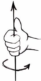
When the current in one half of the conductors in the coils (i.e., one of the bifilar elements in each coil) of the device is moving up, both the current and the magnetic field follow the right-hand rule:


The resultant motional E-field would be vertical to both and inwardly directed.

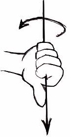
At the same time the current in the other half of the conductors in the coils is moving down and both the current and magnetic field follow the right-hand rule:


The resulting motional E-field is again vertical to both and inwardly directed.

Thus, the resultant field intensity is double the intensity attributable to either one of the set of coil conductors taken singularly.

Expressed mathematically:  E = (B x V) + (-B x -V) = 2 (B x V)


Walt Rosenthal told us also:


All of the information one needs is right there, that's more than enough, to understand how the VTA worked. Walt Rosenthal bless his soul was a great man!

I have said it before, the VTA was just a Blocking Oscillator:


Best Wishes,

   Chris

  • Liked by
  • Antares
  • Augenblick
Adam posted this 13 November 2024

Redirecting the magnetic field allowing the Bloch wall to move.

This is dirty but shows the point.


Adam.

  • Liked by
  • Alex ⋐˙⋮⋮˙⊃
  • Augenblick
Chris posted this 14 November 2024

Hey Adam,

I am not sure you understand? Your image and video does not follow the laid out criteria.

Not sure what you are trying to achieve here?

Best Wishes,

   Chris

  • Liked by
  • Augenblick
Adam posted this 14 November 2024

Moving the Bloch wall.

Same basic setup as the VTA.


Magnets on the ends in attraction with steel between them and a gap. When static the Bloch wall should be near the gap and as the primary coil fires and attracts the magnetic field closest to it, the Bloch wall moves closer to the magnet as we can see the small magnet detector moving with the Bloch wall movement in the video.

This was an attempt to show the movement of the wall.


If I had coils on the steel the Bloch wall should move through them creating power.

Is this not what the primary coil is doing?

This is my understanding, is this incorrect?


Thanks.

Adam.

  • Liked by
  • Alex ⋐˙⋮⋮˙⊃
  • Augenblick
Chris posted this 14 November 2024

Hey Adam,

Drawing Current from Partnered Output Coils as was explained by Floyd Sweet gives Inward direction:

The principle of superposition states that; "In order to calculate the resultant intensity of superimposed fields, each field must be dealt with individually as though the other were not present".

The resultant is obtained by vector addition ( 1 + -1 = 0 ) of each field considered singularly. Consider for a moment the construction of the triode which includes the bifilar coils located within the fields of the two conditioned magnets.

When the current in one half of the conductors in the coils (i.e., one of the bifilar elements in each coil) of the device is moving up, both the current and the magnetic field follow the right-hand rule:


The resultant motional E-field would be vertical to both and inwardly directed.

At the same time the current in the other half of the conductors in the coils is moving down and both the current and magnetic field follow the right-hand rule:


The resulting motional E-field is again vertical to both and inwardly directed.

Thus, the resultant field intensity is double the intensity attributable to either one of the set of coil conductors taken singularly.

Expressed mathematically:  E = (B x V) + (-B x -V) = 2 (B x V)


So, in the middle, directly in the middle, we have a North North Opposing set of Fields:


Right in the Middle, where the Perspex plate is, we see a North North facing Field, squeezing out side ways, because we are Drawing Current from the Partnered Output Coils, this Changing Flux, North North Field, is Changing in Time, which Induces a Voltage in the Drive Coils. 


Like Floyd said: Expressed mathematically:  E = (B x V) + (-B x -V) = 2 (B x V) where each single V x B is a single Partnered Output Coils Generated E.M.F. E = (B x V) is how they used to calculate a value for E

The Drive Coils are a path of Low Reluctance for the Flux, because they have big heavy Cores in there, like yours, that shift the Flux back on the Magnet, like your last set of diagrams. So its in the middle, not at the bottom, and the Magnetic Fields are Induced, not Supplied or Applied. There is a big difference here, from what you were showing, which is quite confusing for anyone wanting to learn. An induced Voltage is different from an Applied Voltage giving us Driven Effects, not Induced effects.

As I said before, the Fields are: S N S N N S S N

Here, the Bloch Wall, or the Plane of Inertia changes, from the Center of the Machine, three Planes of Inertia.

Between the N N is the Perspex Plate shown. These Fields are Generated Fields, and they Squeeze out the Side, in the Middle, a North North Field, which Induces the Voltage in the Drive Coils, like Walt said. Here is a close up showing the Big Core is in the middle:


I appreciate your experiments and your Intellect in your posts, but I really need to make sure others are not being led astray by confusing information.

We really need to make sure anyone reading can read and understand to the best of our abilities.

Best Wishes,

   Chris

FringeIdeas posted this 05 February 2025

Chris,

Regarding your latest build you have shown recently above, here..

I went and purchased a few magnets of the same size. I'm still investigating a bit of this Melnichenko stuff first, but I'd like to start slowly designing a former and join in on this build of yours. The large CSA and the use of magnets has my attention, and I'd like to experiment with this soon. But I had a few questions while looking at your pictures, if you might have a free minute to answer.

In this first picture you show what looks like two POC coils. I assume CW and CCW.


Then you show a continuation of the build, over several pictures, starting with this one.

So, the first question would be, is this just two standard POC coils with one input coil wound on top of one of them? Or is this an, I'll use the word unusual, configuration of input wires on top of the POC coils? Sorry, it's a bit difficult to tell from the pictures.

Additionally, I have the following questions:

  1. I assume you are using 0.8 mm wire? Maybe a bad assumption, it just seems standard for experiments.
  2. Are there additional coils not yet shown, for feedback? Or is this a complete build as far as wire is concerned? Feedback has joined my interests lately.
  3. Are you winding the coils to match the magnetic field strength of the magnets in some way, or is that irrelevant?
  4. The gap between the coils, I have read, is around 3-4 mm. Is this calculated or just what resulted from the former build?
  5. I have a microwave oven core, rather large, that I would like to dissect it and use laminates for the cores of this build. Standard microwave oven transformer metal like this should be sufficient, correct? As I am just assuming that you are aiming for 60 Hz.

I guess that is it for the questions for now. I'm trying to write this in between the whines and cries of the children, and it's been a long work day, I think I'll quit while I'm ahead and get this posted 😀

As always, thank you!

Marcel

Chris posted this 10 February 2025

Hey Marcel,

There is always something to learn from any experiment!

I have build several setups like this before and there are some issues that still don't make a huge amount of sense to me:

  • The Total Reluctance seems too high - I am not sure how Floyd Sweet avoided this issue.
  • Same problem with Voltage exists, its difficult to get the Voltage up, the Magnetic Fields stop Voltages from being "Generated" - More on this issue later.
  • Floyd Sweet clearly had a working machine that was a very impressive output for the size of the machine - I have not reached his level yet, so I am still missing a few things.
  • Tom Bearden's MEG is an adaptation of Floyd Sweets VTA, I am sure of this, but Floyd Sweet was able to take this to the next level.


My Friend, your Questions:

So, the first question would be, is this just two standard POC coils with one input coil wound on top of one of them? Or is this an, I'll use the word unusual, configuration of input wires on top of the POC coils? Sorry, it's a bit difficult to tell from the pictures.

Standard POC Coils, two wound with 0.8mm wire @ 247 turns I believe.

Additionally, I have the following questions:

  1. I assume you are using 0.8 mm wire? Maybe a bad assumption, it just seems standard for experiments.

Yes 0.8mm wire @ 247 turns I believe.

  • Are there additional coils not yet shown, for feedback? Or is this a complete build as far as wire is concerned? Feedback has joined my interests lately.

Three Coils in total, one POC has a Coil wound over the top, in the same fashion we have been experimenting with for a while now.

  • Are you winding the coils to match the magnetic field strength of the magnets in some way, or is that irrelevant?

At a specific Current, through turns X, we will match the Magnets Field strength, yes.

  • The gap between the coils, I have read, is around 3-4 mm. Is this calculated or just what resulted from the former build?

I uses a small bit of plexiglass sheet I had left over, it was 3mm, acrylic sheet.

  • I have a microwave oven core, rather large, that I would like to dissect it and use laminates for the cores of this build. Standard microwave oven transformer metal like this should be sufficient, correct? As I am just assuming that you are aiming for 60 Hz.

I believe most cores will work. In the past I have said some cores are slugs and dont seem to work. I think this is for very slow cores, but you can get results from slow cores with larger coils. Any core is worth trying!

I guess that is it for the questions for now. I'm trying to write this in between the whines and cries of the children, and it's been a long work day, I think I'll quit while I'm ahead and get this posted 😀


Of course, the goal is to get the Magnetic Fields Up, the Voltages up and hold the Magnetic Fields High with the Bucking Magnetic Fields, which Pumps Current, the smart, wise implementation is the key!

In the early Kapanadze devices, he used a Spark Gap, the Injection of a sharp transient, used to shock the Coils, can get the voltage up, and the fact that we know there was a specific polarity, shows that the Voltage increase must be in the correct direction, which is obvious! Remember, Floyd Sweet gave us this image:

Newton said:

What goes up, must come down!


All Magnetic Fields produced, must come back down to Equilibrium, so the Regaging process must occur, weather we use it of not, that's entirely up to the Design Specification we put into place!

Smart people will take advantage of what we have shared, many wont.

Best Wishes,

   Chris

FringeIdeas posted this 13 February 2025

Chris,

I'm finding a free minute to reply. Just wanted to say thank you for the answers. I believe this weekend I might be able to find some time to start putting something together. I'll get this going along side of the Melnichenko experiments.

Again, much appreciated.

Marcel

Chris posted this 13 February 2025

Hey Marcel,

I believe, the MEG is the inside out version of the VTA, Magnets on the Inside, compared to the VTA Magnets on the Outside.

I believe Floyd Sweet had a flat plate linking the two Coils to reduce the Reluctance of the Core.

I may be wrong, but my experiments point to this being a very strong possibility.

Best Wishes,

   Chris

We're Light Years Ahead!
Members Online:
What is a Scalar:

In physics, scalars are physical quantities that are unaffected by changes to a vector space basis. Scalars are often accompanied by units of measurement, as in "10 cm". Examples of scalar quantities are mass, distance, charge, volume, time, speed, and the magnitude of physical vectors in general.

You need to forget the Non-Sense that some spout with out knowing the actual Definition of the word Scalar! Some people talk absolute Bull Sh*t!

The pressure P in the formula P = pgh, pgh is a scalar that tells you the amount of this squashing force per unit area in a fluid.

A Scalar, having both direction and magnitude, can be anything! The Magnetic Field, a Charge moving, yet some Numb Nuts think it means Magic Science!

Message from God:

Hello my children. This is Yahweh, the one true Lord. You have found creation's secret. Now share it peacefully with the world.

Ref: Message from God written inside the Human Genome

God be in my head, and in my thinking.

God be in my eyes, and in my looking.

God be in my mouth, and in my speaking.

Oh, God be in my heart, and in my understanding.

We love and trust in our Lord, Jesus Christ of Nazareth!

Your Support:

More than anything else, your contributions to this forum are most important! We are trying to actively get all visitors involved, but we do only have a few main contributors, which are very much appreciated! If you would like to see more pages with more detailed experiments and answers, perhaps a contribution of another type maybe possible:

PayPal De-Platformed me!

They REFUSE to tell me why!

We now use Wise!

Donate
Use E-Mail: Chris at aboveunity.com

The content I am sharing is not only unique, but is changing the world as we know it! Please Support Us!

Thank You So Much!

Weeks High Earners:
The great Nikola Tesla:

Ere many generations pass, our machinery will be driven by a power obtainable at any point of the universe. This idea is not novel. Men have been led to it long ago by instinct or reason. It has been expressed in many ways, and in many places, in the history of old and new. We find it in the delightful myth of Antheus, who drives power from the earth; we find it among the subtle speculations of one of your splendid mathematicians, and in many hints and statements of thinkers of the present time. Throughout space there is energy. Is this energy static or kinetic? If static, our hopes are in vain; if kinetic - and this we know it is for certain - then it is a mere question of time when men will succeed in attaching their machinery to the very wheelwork of nature.

Experiments With Alternate Currents Of High Potential And High Frequency (February 1892).

Close