Hi Community,
it took me quite some time to step forward and start sharing my experiments, so here we are 
Current Knowledge
The observations I provide are based on my current understanding and experiments. I don't have "the truth", but I'm in the search for it  I want to focus on understanding and mastering the effects, measurements are in the second place.
Details
I'll try to be as precise as possible with details, so that you can replicate and proof if you like. I will answer to questions as best I can. I will provide part numbers and links to the equipment I use.
Focus
I will ask to stay focus on the experiments provided. If you have new ideas, please make a new Thread and provide a link to it. I will ask Chris to (re)move posts, which diverge peoples attention to get down the rabbit hole. I ask you to respect this
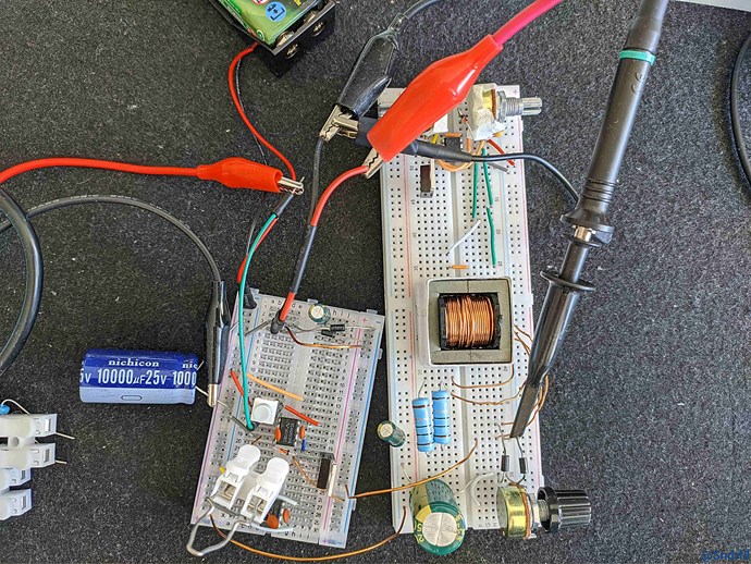
Equipment
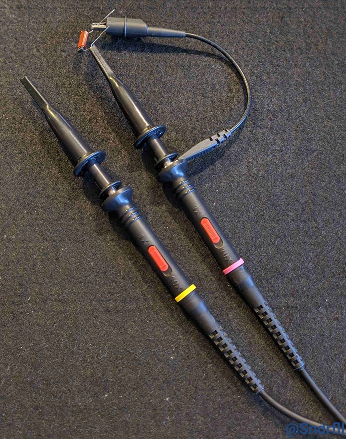
- Digital Signal Oscilloscope (DSO): [Rigol MSO5072] Easy to be upgraded
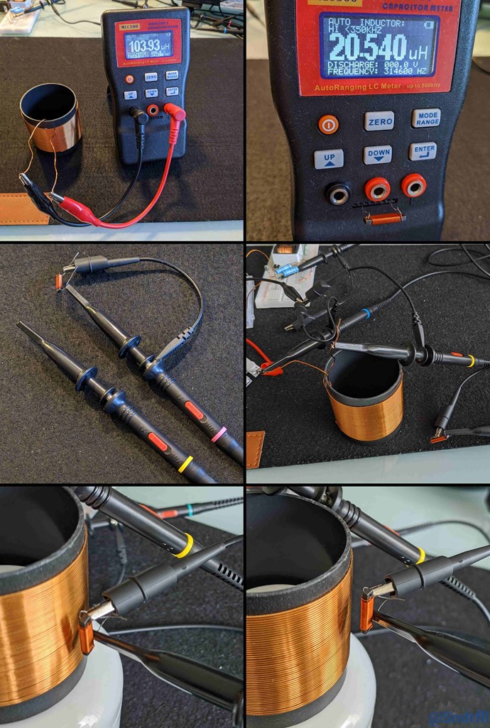
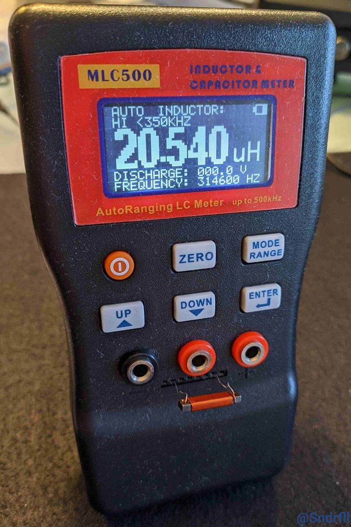
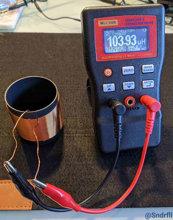
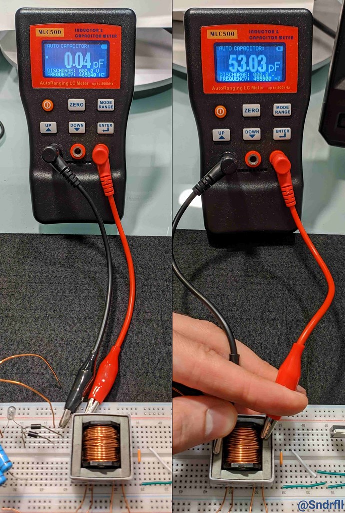
- Inductance/Capacitance-Meter (LC): [MCL500]
- Signal/Function-Generator: [FY2300-6 MHz]
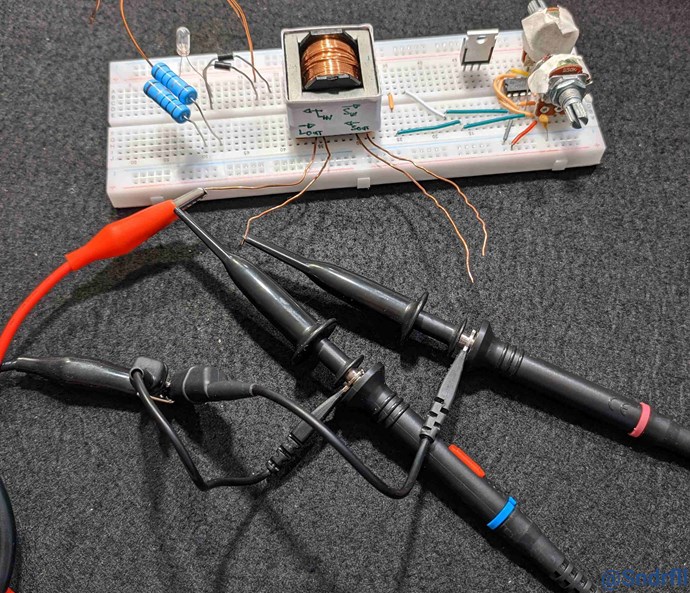
Experiments / Machines
- MOSFET-Driver-IC: [TC4420]
- MOSFETs: [IRF3205]
- Current sensing resistor (CSR): [Constantan 50mR / 0.05 Ohm]
- Toroid Core [Sendust]
- ETD Core [ETD Ferrite Core]
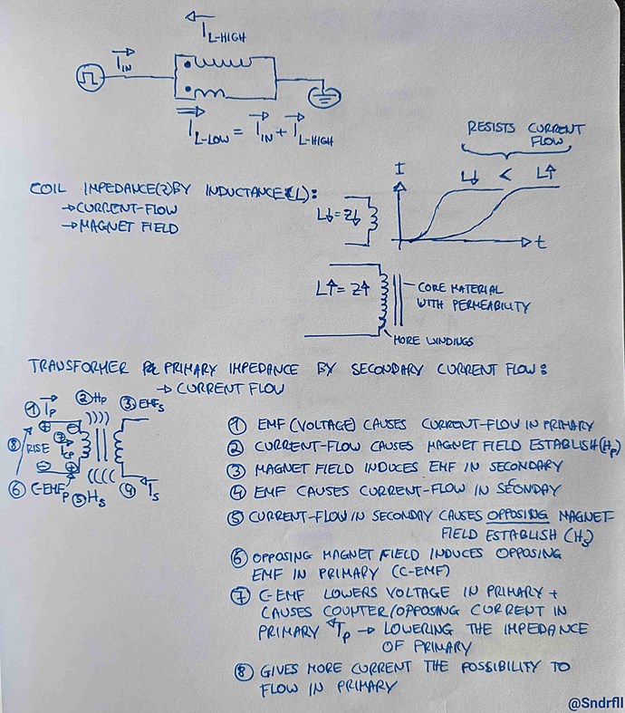
Winding direction of coils
- Depending on the winding direction of the coils the magnetic flux is oriented in different directions.
- The dottet line means the wire is "running behind the core".
- If you want to make the fields oppose use the right hand grip rule to find out the direction of the magnetic flux.
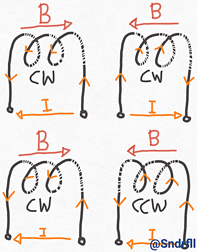
To check magnet flux orientation use an LC-meter and connect the two coils in series.
- The configuration with the lower inductance (L1-L2) means opposing fields (Reduced impedance?).
- The configuration with higher inductance (L1+L2) means adding fields.
WARNING: Keep in mind that the magnetic flux in a loop core (CC or toroidal) core is the opposite on the two "sides" of the core. So if your coils are on opposite sides, make a drawing of the magnetic flux to visualize better.
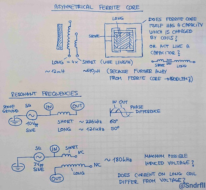
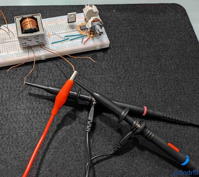
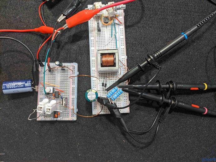
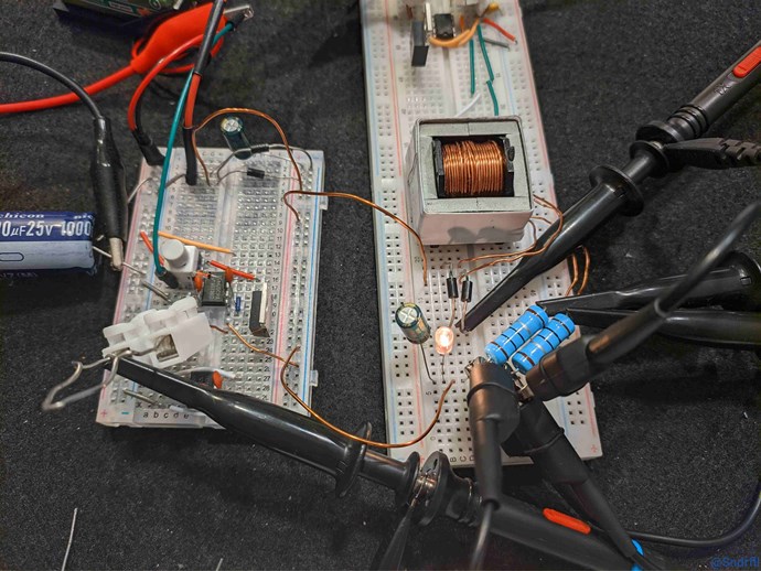
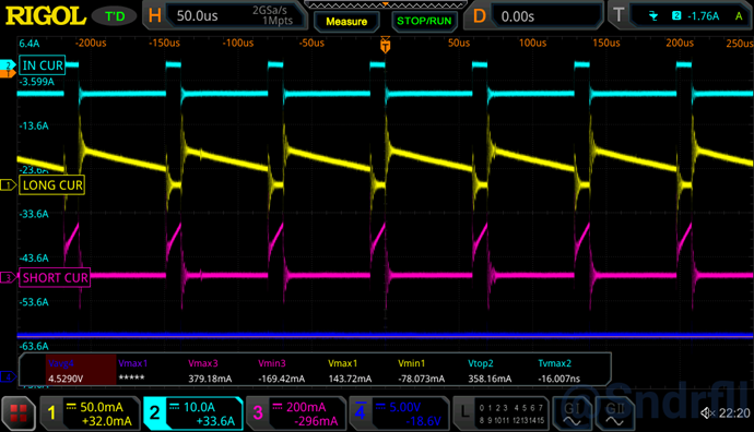
MrPreva Experiment
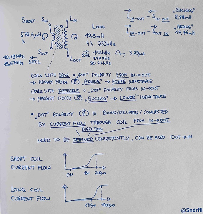
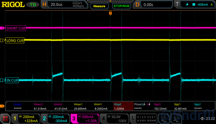
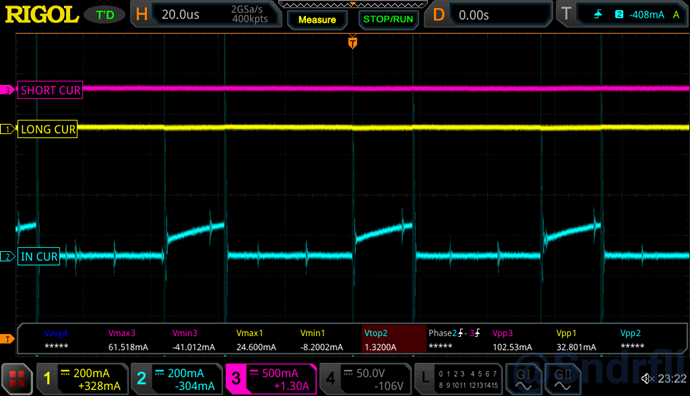
Lower inductance of SHORT coil allows for quicker (time) current to flow through coil VS LONG coil.
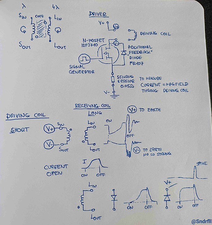
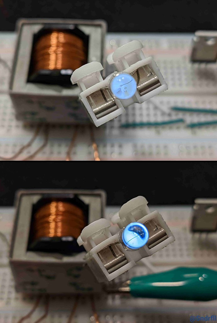
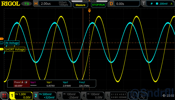
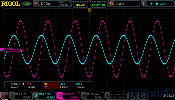
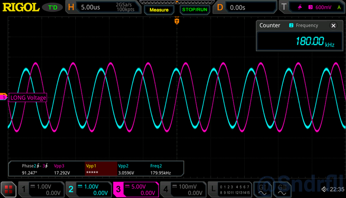
Driving SHORT coil and checking generated (EMF) output voltage on the LONG coil.
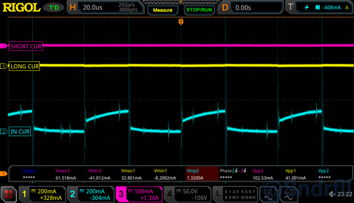
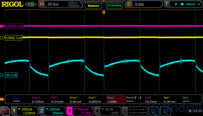
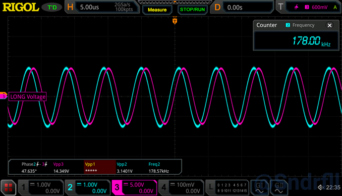
SHORT (L-LOW) coil induces voltage (EMF) in LONG (L-HIGH) coil. Current in LONG coil adds to current in SHORT coil.
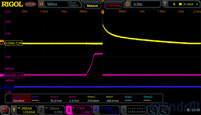
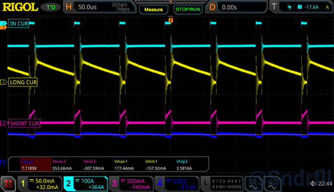
Signal generator input (DC pulse to gate driver @20 Hz, variing the length of the pulse). Pulse must be long enough to observe different phases of coil interaction (in this case > 2ms).
Starting using low frequency to not damage MOSFET.
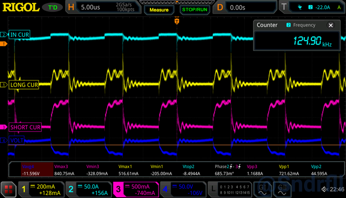
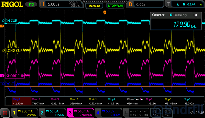
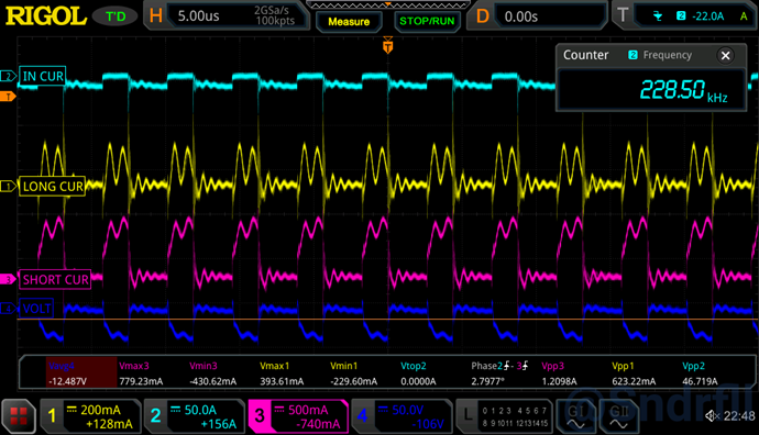
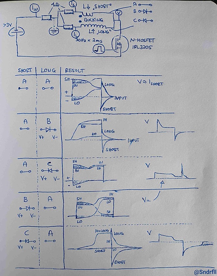
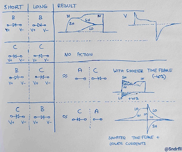
Placing different diode combinations on low voltage (MOSFET Drain) side between coils.
Current adding behavior marked in diagramms.


 )
)


 )
)