My Friends,
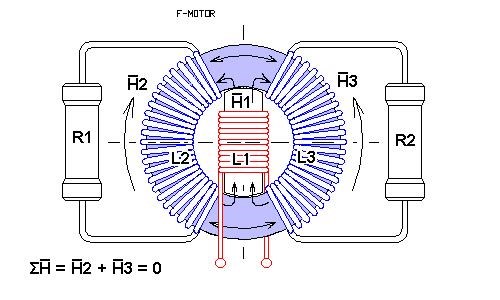
Pointed out above, with the Electromagnetic Induction Schematic and Turns on a Transformer, The Magnetic Fields in a Transformer have a specific relationship to each other.
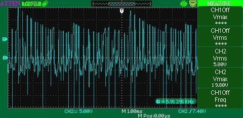
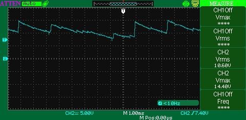
I have asked the question before: "Why is our Voltage so low? Why such a large Voltage Drop?" - None picked up the Ball.
Of Importance, Turns and Winding Directions also have a specific relationship to each other:
Buck Boost Transformer
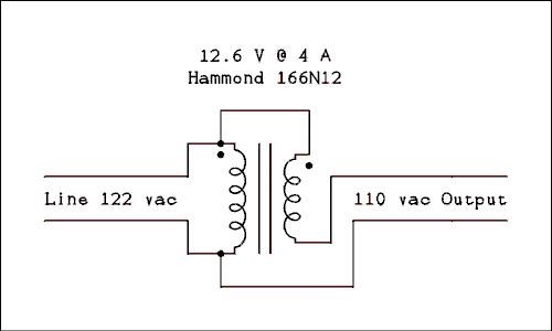
Notice for each Turn that is Bucking to the Primary, Voltage is reduced.
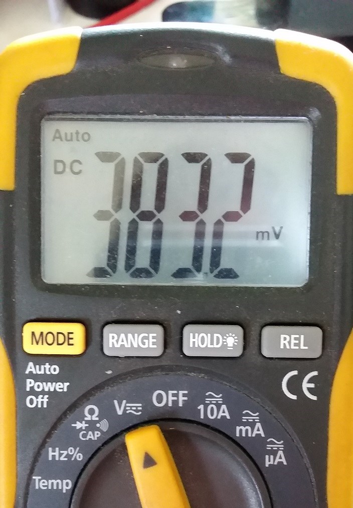
- AC Voltage Input = 122
- AC Voltage Output = 110
122 - 110 = 12 Volts reduction. This is really important to see. Remember what I said
Two things you need to know:
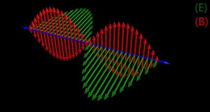
Opposing Magnetic Fields produces Current
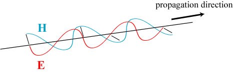
Changing Magnetic Field produces Voltage
Amplifying Voltage
Voltage is very easily Amplified! Standard Transformers do it every day, 10 : 1 Ratio will give an Output of: 22 Volts for 220 Volts input. A Step Up Transformer is just the other way around, 1 : 10 Ratio. 22 Volts input will give 220 Volts Output.
It is the Change in the Magnetic Field in respect to a Conductor with Turns N, simply: E.M.F = -N dΦB/dt
Amplifying Current
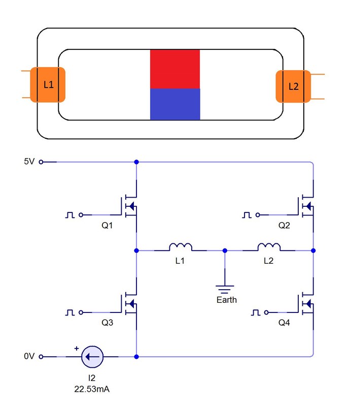
Really important to note, we have seen many experiments that show Amplifying Current is a very easy thing to do! All our recent experiments show such simplicity in the Magnetic Field interactions. These, the exact same effects we see as Self Induction in a Coil:

Ref: http://www.nde-ed.org/EducationResources/CommunityCollege/EddyCurrents/Physics/selfinductance.htm
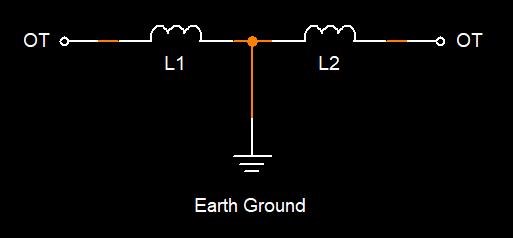
Bucking Magnetic Fields do not allow for Changing Magnetic Fields. For this reason, Voltage will be low. Much like our investigation of the Common Mode Choke.
EDIT: To clarify, in Context, from my above quote:
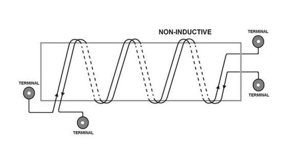
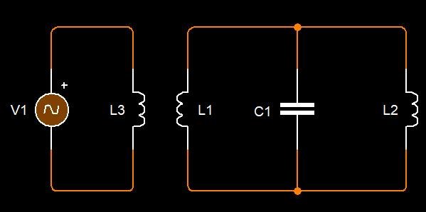
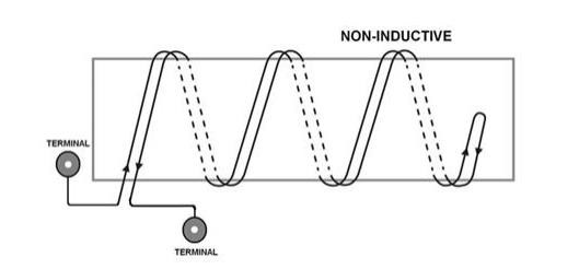
One must remember, a Voltage or E.M.F is induced via Electromagnetic Induction, Changing Magnetic Field, so an Output Coil with 10 Turns Clockwise and 10 Turns Counter Clockwise, means Zero E.M.F will be induced, thus the term Non-Inductive.
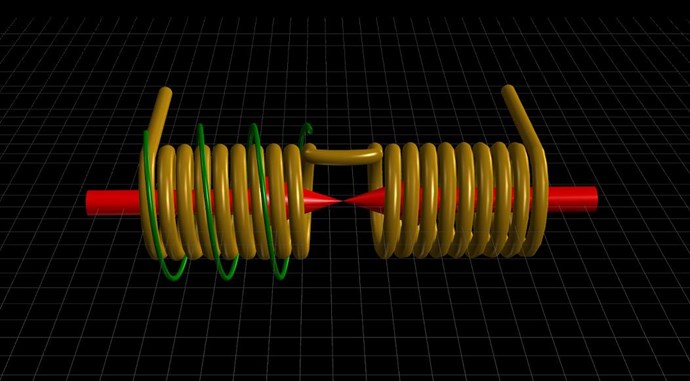
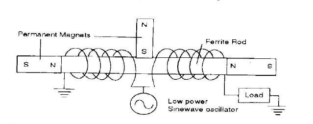
If you study Tariel Kapanadze's Grenade Coil:
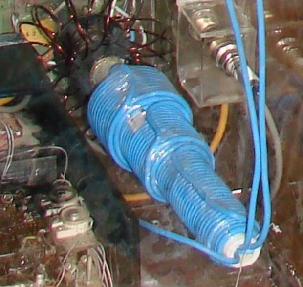
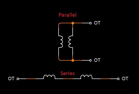
You will find that Turns Counter Clock Wise are greater than Turns Clock Wise, and this Coil, which should be thought of as two separate Coils, is Series Connected Partnered Output Coils: CW and CCW respectively.
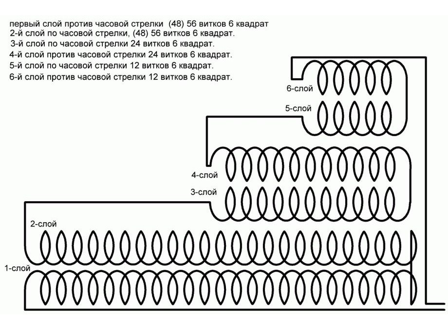
My count works out to be around 1 : 3 ratio. This is why Ruslan told us:
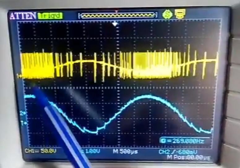
I repeat, you need to make the voltage on this harmonic not 10-20 volts, but higher by an order of magnitude. Approximately up to 50-60 volts and get the same dancing effect at the output.
One third of 200 Volts is 60 Volts! I hope you can see this important fact!
Of course, not forgetting:
The output voltage will be 195-200 volts.
The Coils Turns Opposing: 1 : 3 ratio like the KapaGen, we have seen before: ( Andrey Melnichenko )
Tariel Kapanadze also gave Credit to Andrey Melnichenko: ( @37:13 /watch?v=3utQUdGDMmU )

Please Remember, there are many ways this can work! This is really important to keep in mind! However, as Don Smith said:
It is possible to have all Amperage or all Voltage from these Coils. One must take a logical approach and keep this in mind.
For most, this post should answer a lot of questions.
Chris