Hey Adam,
My Friend, you're most welcome, you're doing a really good job! Well done!
You are mostly right!
A Current can only flow in a Coil if there is a Voltage exists, that means, the Terminals of the Coil must have a Potential Difference, a "Generated" Voltage.
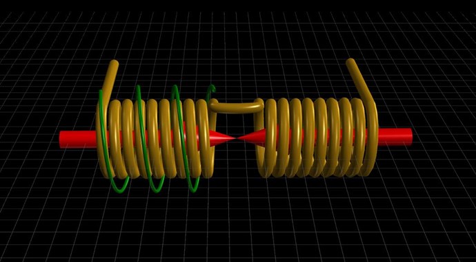
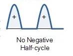
The Magnetic Field of the Primary does have two phases, a Ramp Up Phase:
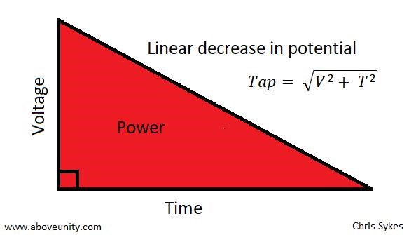
and a Ramp Down Phase:
At TOn the Coil experiences di/dt, changing Current I, over Time t, which represents the very same change in Magnetic Field. Current I is analogous to the Magnetic Field B.
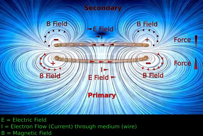
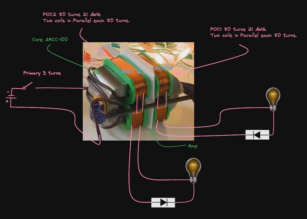
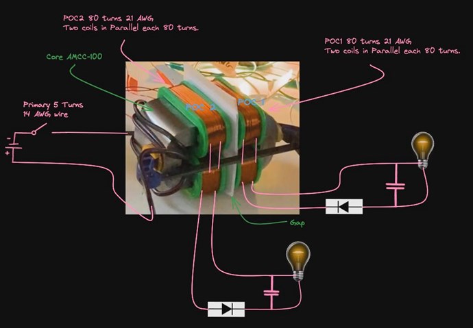
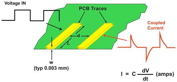
Every single Coil that experiences di/dt, can be used as a Source for Electromagnetic Induction. This Coil can be, Primary, Secondary, or a PCB Trace on a PCB Board, where Engineers work very hard to stop what they call Parasitic Inductance:
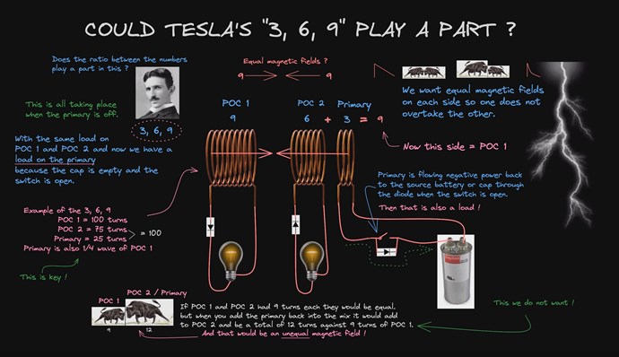
The Coupling of Inductive Components, gives rise to Charge Separation, via Electromagnetic Induction, which we want to focus on and take to a new level, Asymmetrical Electromagnetic Induction, well beyond the current Symmetrical Electromagnetic Induction bounds, where: Output = Input - Losses, never able to become Above Unity!
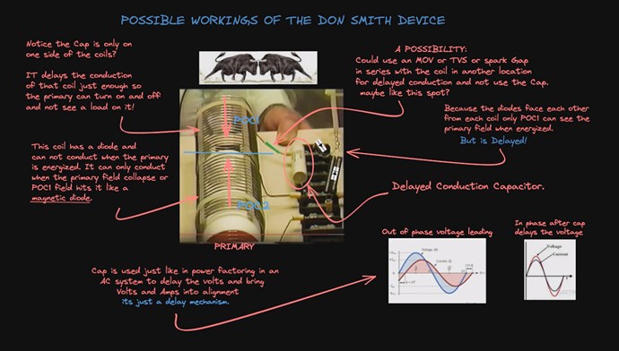
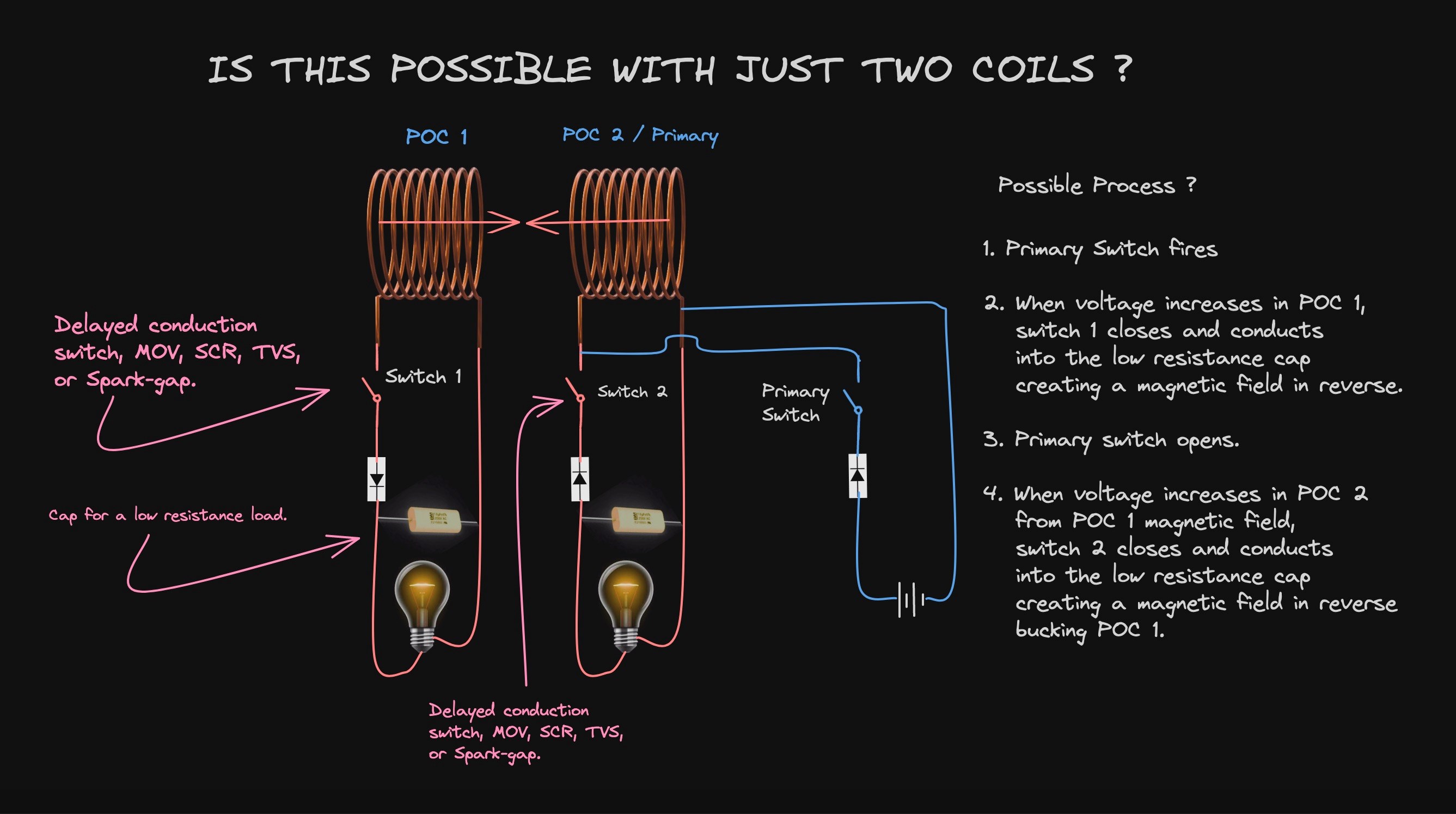
My Research leads me to believe, all of the Action Reaction and Counter-Reaction's occur simultaneously, but with slight time delays, I call this Delayed Conduction, before the DUT reaches Peak Potential.
Time = T0
Everything is static, nothing is occurring.
Time = T1
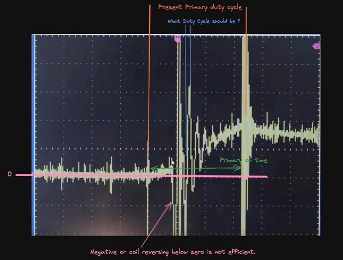
The Mosfet turns on, TOn, and the Input Coil starts ramping up in Current, the period we are interested in, is τ, Tau, the 5 Time Constants, from TOn, to reach peak Magnetic Field in Time t, after that, there is no point having the Input Mosfet On, as we are wasting Current, I2R Losses. As there is no more 'Change' in the Input Coil's Magnetic Field B, the Input Coil can not "Generate" any Voltage V.
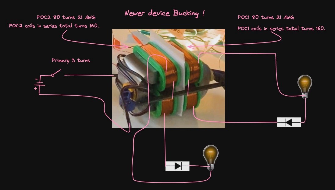
During Time = T1, we see POCOne's Voltage going up to Peak Voltage V, which is directly linked to the Input Coils Change in Magnetic Field, via Faradays Law: E.M.F = -NδΦ/δt, because POCOne is loaded, Ohms Law states: I = V / R, and thus the Current I flowing in POCOnes Circuit will be the product of the Resistance and Impedance, and the Voltage V "Generated".
Also, during Time = T1, we have a Current building, δi/δt, in POCOne, which we calculated, which can be used as a Source, for Electromagnetic Induction to occur again, giving us the ultimate, Asymmetrical Electromagnetic Induction machine, but, only if we take advantage of this beautiful Natural Law.
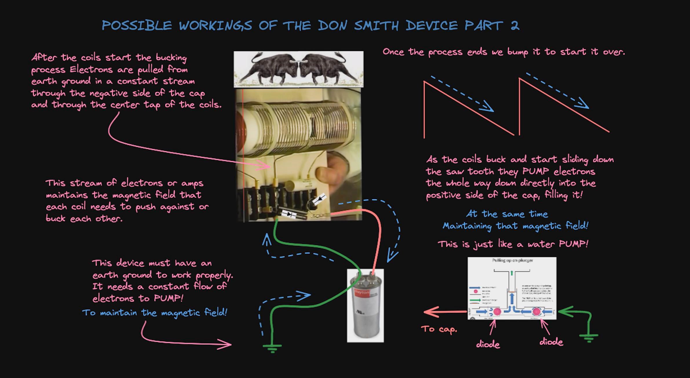
This Changing Current δΦ/δt, "Generates" a Voltage V in POCTwo, and as a result of this Loaded Circuit, we get the same situation occurring, the Current building, δΦ/δt, gives us a feedback mechanism, which in turn makes the LED Glow more brightly, and because we have an Asymmetrical System, we can draw more power from it under certain circumstances. Its an Open System, its not a Closed System, and therefore does not have to abide by Conservation of Energy Law.
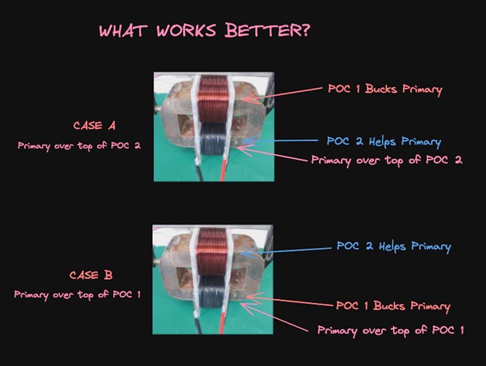
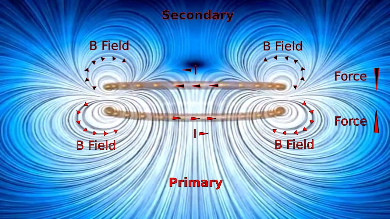
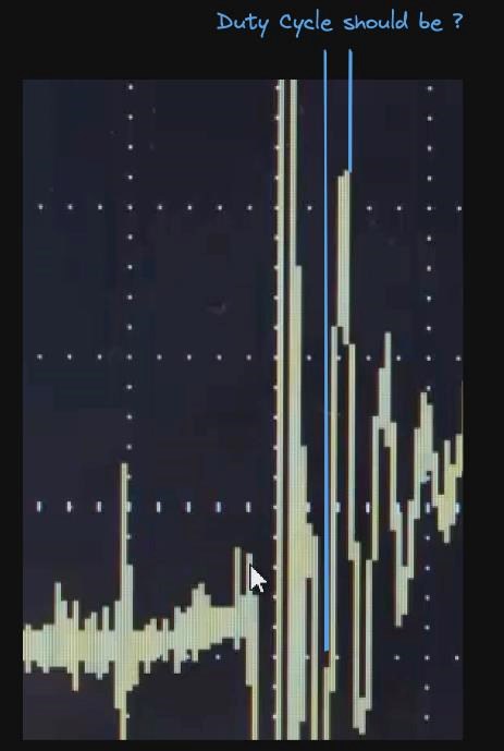
During this Time T = T1, we have a Slapping together of the Partnered Output Coils, they are Bucking each other with all the Magnetomotive Force they can, Peak Potential is reached:
All of this happens where I have marked Important, this is one Time Slice.
Time = T2
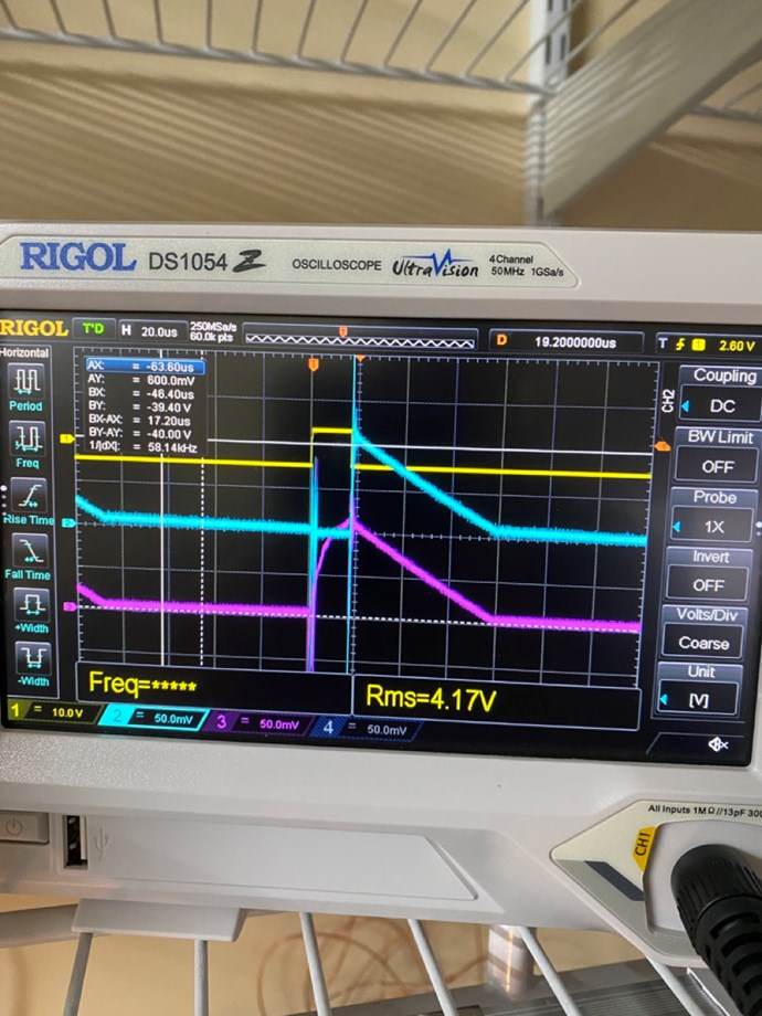
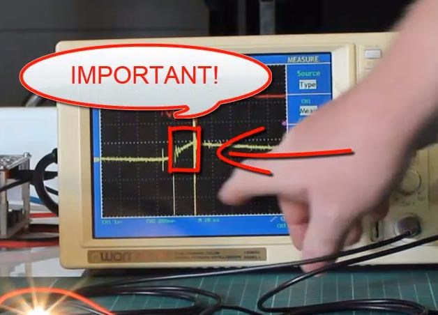
The Input Coil's Mosfet is turned off, TOff, and the Current to the Input Coil no longer flows from the Source to the Input Coil. However, this does not mean no Current Flows, we do have Current Flowing:
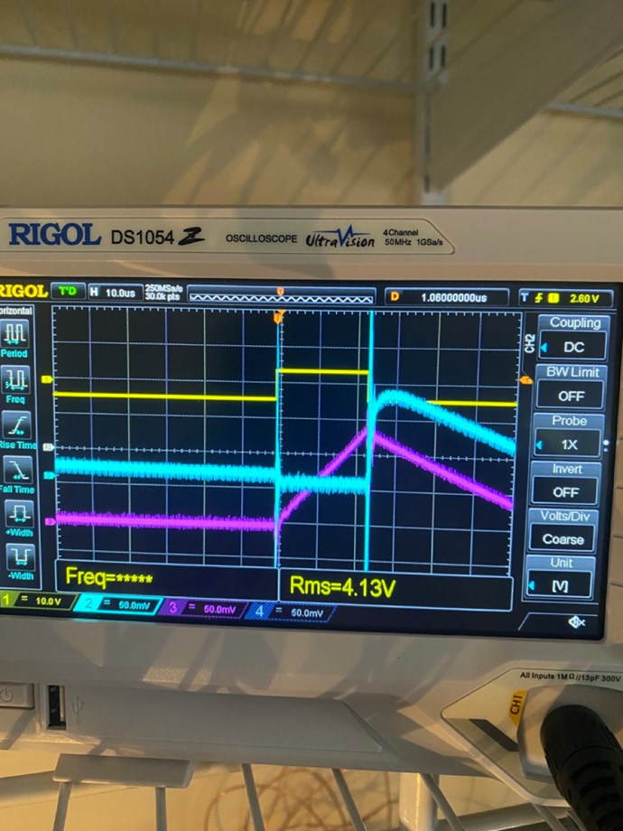
Here is an example:
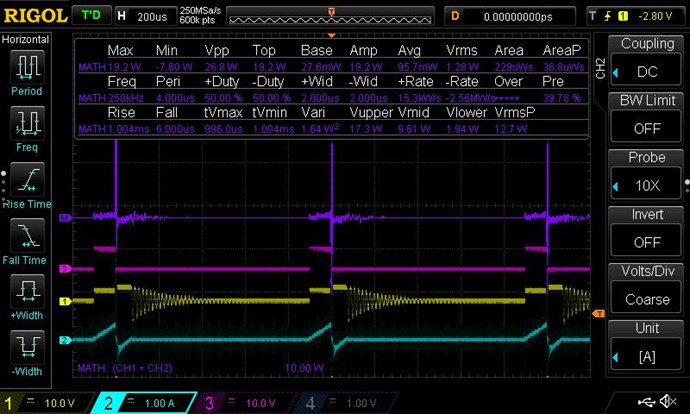
Where:
- Purple Trace is the Math, showing Positive and Negative Power.
- Pink Trace is the Gate Signal to the Mosfet.
- Yellow is the Input Voltage.
- Teal Trace is the Input Current, both Positive and Negative.
I must apologise, I have better examples of this, but do not wish to confuse everyone. This example is sufficient to show what I am talking about.
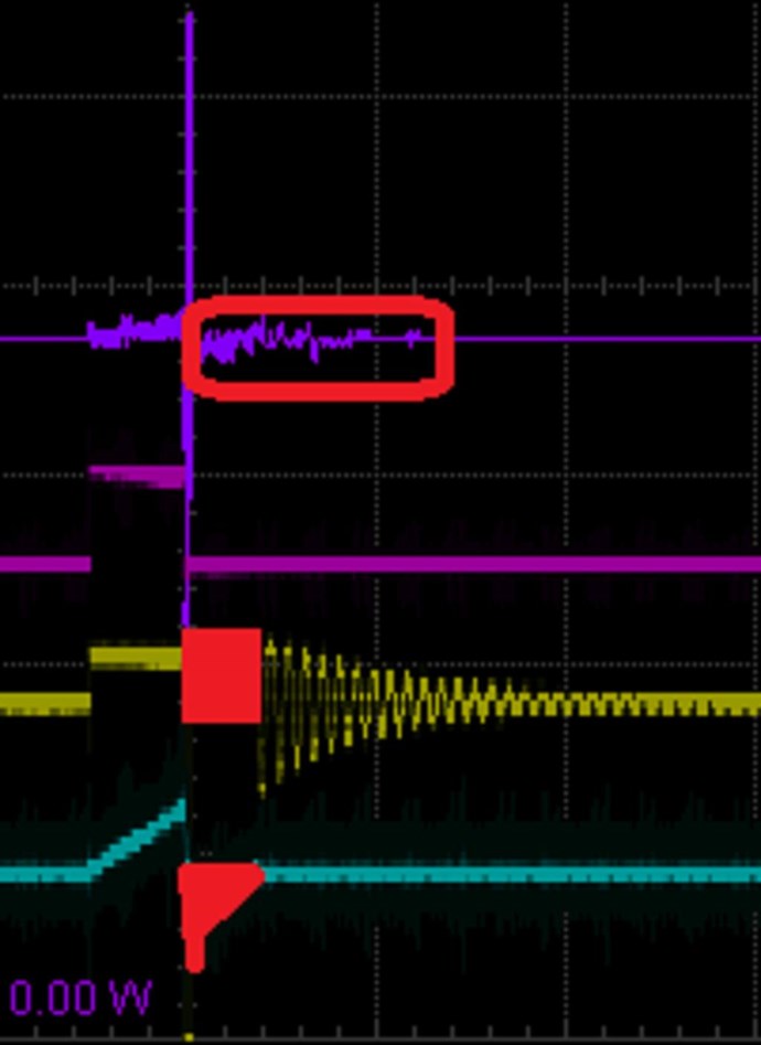
Again, marked in Red, Positive Voltage and Negative Current, you have Negative Power. Not Negative Energy, Negative Power, I hope people do not confuse this as I believe people have in the past.
I hope this helps others when doing experiments, knowing what to look for is very important!
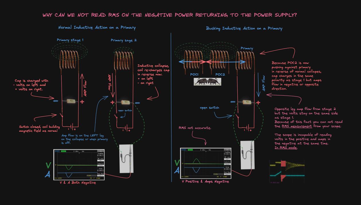
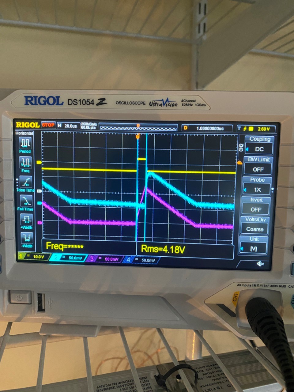
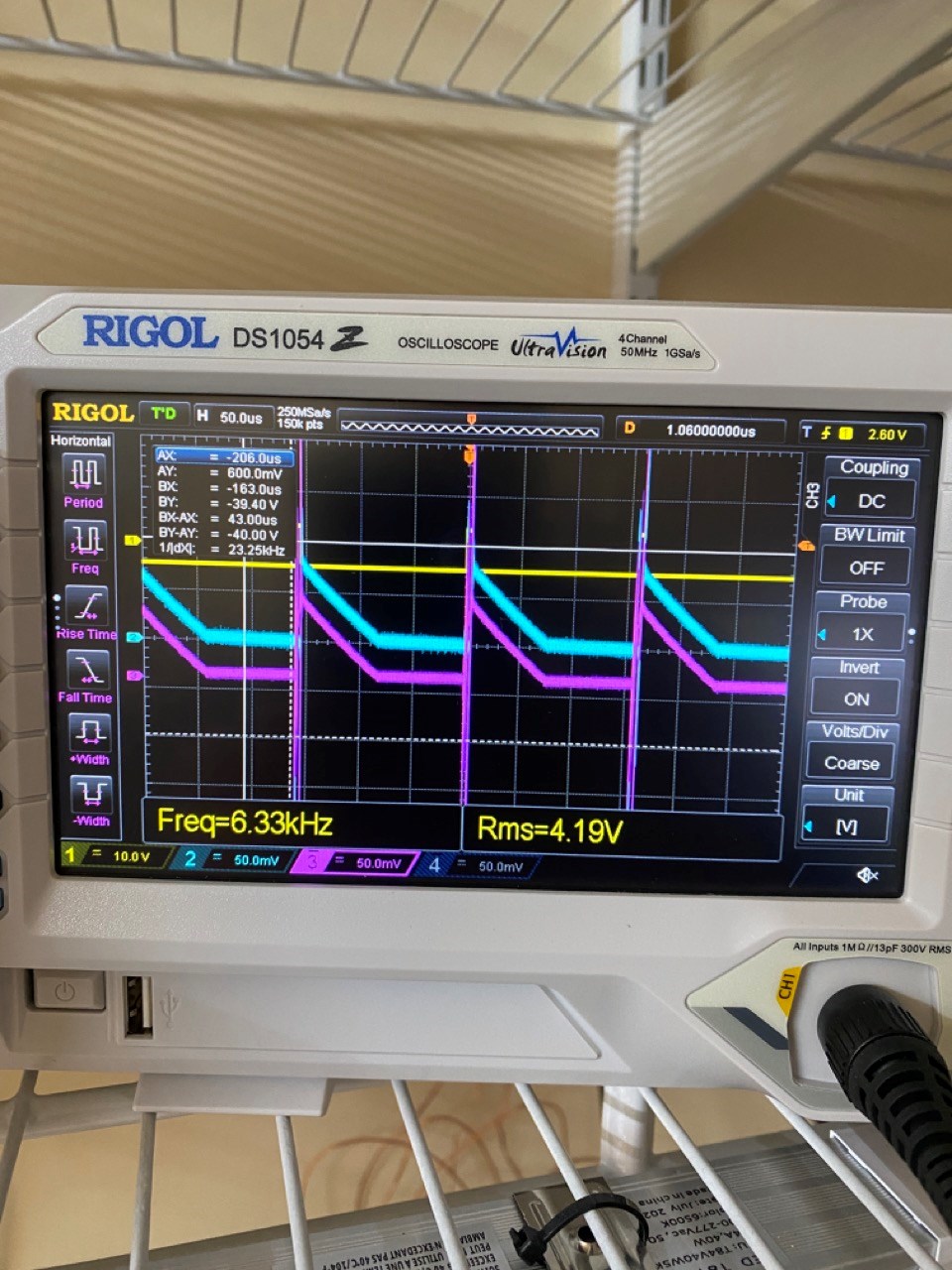
Remember: This is the very reason you can NOT Use RMS Measurements on the Input! See Measurements Thread and see the above Figures:
- Average: 95.7 mW
- RMS: 1.28 W
A Huge error here! 1.28 - 0.095 = 1.185 Watts. 13.474 times!
At TOff, we have Current going back to the Input Power Source! Because of our Asymmetrical Configuration, or our DUT, the used Power is a small fraction of the actual Active Power! We have a large Reactive Component here, most of the Input Power goes back to the Input Power Source! Its Reactive, Ping Pong Power!
Does this ring a Bell?
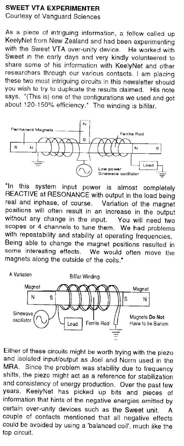
REACTIVE at RESONANCE... I hope all readers can see where I am heading?
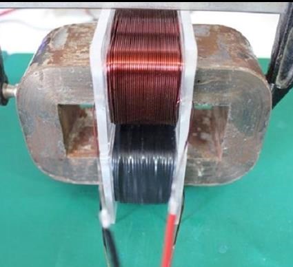
At the same Time, our Partnered Output Coils are Bucking Each Other, so the Fields here are being supported, held High, a method described, but not clear, by Floyd Sweet:
They are now able to simply support mass, as demonstrated with the transformer steel illustration.
Does a Magnetic Field have Mass?
The Magnetic Fields slowly reduce in Strength H, over Time t, as the I2R Losses and the Load, consume power.
Note, the Time Constants are not the same! Each Time segment is different, because different things are occurring during these phases.
Forgive my ramblings, I only aim to help.
Best Wishes,
Chris