My Friends,
This thread stems from this post here.
This thread covers a topic that has seen a lot of controversy for a long time! Even many Experienced Electrical Engineers do not know the true function of an Electrical Transformer!
The Conventional Electrical Transformer works entirely on the principle of Faradays Law of Electromagnetic Induction, a topic I have covered in great detail for many years! I have many hundreds of hours of videos on Electromagnetic Induction!
Some introductory videos:
Some of the best Technical Videos on how a Transformer works, I have found are:
I recommend an in depth study of the videos above! This Channel is a very good resource for all EE Related material!
I said in the above referenced post:
Truly, 99% of videos online fall short of explaining How a Transformer works Correctly!
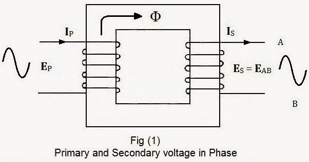
Voltage "Generated" is Sine Opposite, 180 Degrees, and therefore Current I through Turns N, or MMF will also be Sine Opposite.
Two Opposing Magnetic Fields, the Input being slightly greater than the Output, due to Losses, but, the total Transformation is between 85 and 95% Efficient!
Typically M.M.F, Magnetomotive Force does not include a Direction, it is a Scalar Quantity when normally referenced, containing a Magnitude. M.M.F should be thought of as a Vector Quantity, having both Magnitude and a Direction. Again, Magnetomotive Force is the same as Ampere Turns NI, or Magnetic Field Strength, or Intensity H · lc. So, M.M.F is a Force, its the same analogy as Water flowing through a Pipe with Flow of X, a Volumetric Quantity, that has Displacement.
Important: Every Current Flow I, through Turns N, is a M.M.F! Remember: NI = M.M.F! Every Current Flow, no matter what Coil you are observing! Primary, Secondary or what ever Coil! Every Coil has an M.M.F if Current I Flows! This is Ignored entirely in ALL Transformer Theory!
In the above Video:
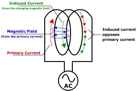
![]()
Here you can see, only One Flux Φ is Drawn, indicating only One M.M.F, but this is Not Accurate! It is true, the Secondary has a Flux Φ which Opposes the Primary! Because this Diagram is accurately Drawn, but the secondary has no load drawn, but Current is shown in the Secondary, the Secondary has its own M.M.F! You can use the Right Hand Grip Rule to show what Direction the Flux Φ will be:
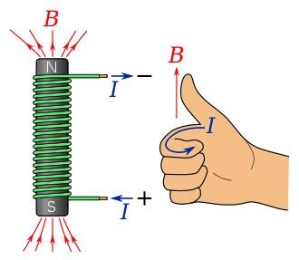
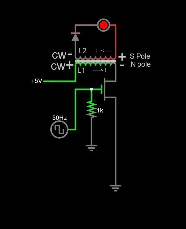
Applying the Right Hand Grip Rule to the above Transformer Image, the Magnetic Field from each Coil can be seen, where each Coil has a North Pole at the top of the Transformer, each Opposing Each Other!
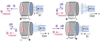
I think it is important to note, the Opposition of the Secondary is Cycle Specific of the Primary, what do I mean:
- Primary North Pole N, increasing in Time t, Secondary North Pole N, increases in Time t, opposing the Action!
- Primary North Pole N, decreasing in Time t, Secondary South Pole S, increases in Time t, opposing the Action!
This image shows the Actions:
Heinrich Friedrich Emil Lenz, formulated Lenz's Law to predict the Negative Voltage! Lenz's Law is an addition to Faradays Law:
E.M.F = - δΦB / δt
Where:
- E.M.F = Electromotive Force measured in Units of Volts.
- -, The Negative Sign = Lenz's Law, which is Sine Opposite to the Source.
- δΦB = The total change in Magnetic Flux Density B in units of Gauss or Tesla, depending on the system one is using.
- δt = The total Time of the Change in Flux δΦB in Seconds.
This is called the Flux Linking Law and refers to The Magnetic A Vector Potential which is covered in Feynman's Lectures:
Lenz's Law does NOT predict Direction of Current! The Direction of Current is assumed:
- Conventional Current flows from Positive to Negative! This is shown in the above Image!
- Actual Current flows from Negative to Positive. Science made a mistake several decades ago and had to fix this mistake called Conventional Current.
Transformer Efficiencies can be very high! It is not uncommon to see between 85 to 95% or more in some cases! Some very big Transformers can be 99% Efficient!
Here is a good benchmark done by Bill Alek:
The Benchmark is seen between: 0 Seconds to 9 Minutes or so.
NOTE: The Conventional Transformer is always below Unity: Output = Input - Losses! This is due to Symmetry! Symmetry of: MMF, Coils, Magnetic Fields, Currents and so on!
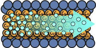
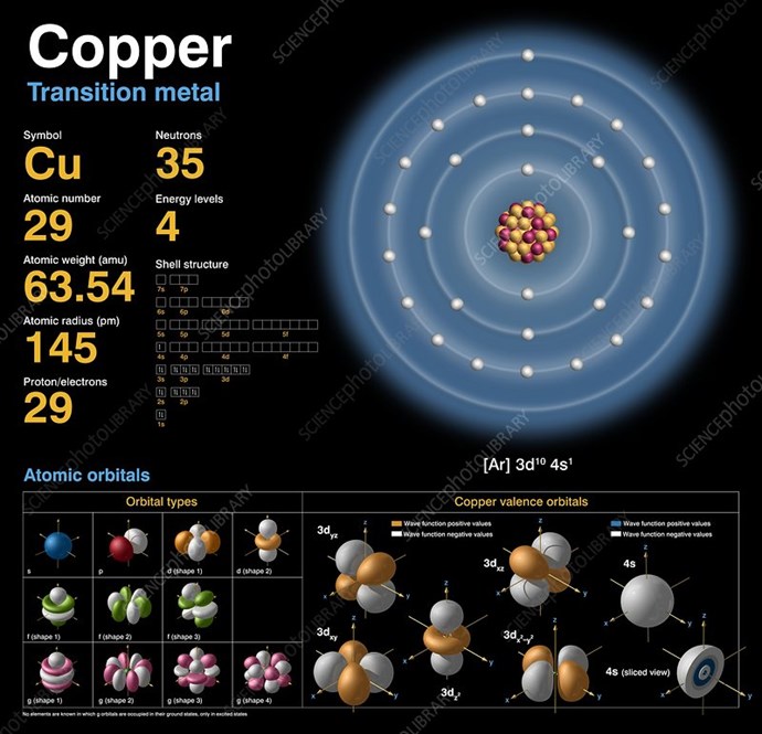
At no time are Charges transferred from the Primary to the Secondary Coils! The Electrically Insulated Coils are entirely Galvanically Isolated! Electric Charge can not pass between the Galvanically Isolated Boundary! So where does the Secondary Charge come from? Source is the Atom! Copper having 29 Electrons per Atom!
Lets not forget, One Ampere is equal to 6.241509074 × 10¹⁸ Elementary Charges, or One Coulomb per Second! One Volt is the Charge Potential of 6.241509074 × 10¹⁸ Elementary Charges, or One Coulomb. Thus, One Watt is One Volt x One Amp, a Volumetric Flow! Definitions are from the SI Units.
Electromagnetic Induction does not need to be Symmetrical, it can be Asymmetrical!
Symmetry means: Equal and Opposite minus Losses - Always Below Unity!
Some statements are the most important and should be learnt from! That's why I decided to learn everything I could about Transformers!
In Tom Bearden's book:
Sweet was also a transformer designer and expert, and he remarked that he had also observed specialized self-oscillation in certain transformers.
Ref: Energy From The Vacuum by Tom Bearden
Ref: Energy From the Vacuum - Part 9 - The Early Years Moray, Sweet and Anti-Gravity - Tom Bearden.
Because of Copyright Removal: Snippet used for Educational Purposes under Fair Use!
NOTE: Magnet Conditioning is a CIA Spoof HOAX!
On rare occasions, Sweet saw this effect, called self-oscillation, occur in electric transformers
Ref: Jeane Manning: A New Physics for a New Energy Source / Free Energy - Making the Impossible Possible
Very simple, Self Oscillation, referenced above, comes from Asymmetrical Electromagnetic Induction and not from anything else!
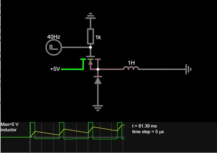
Experiment is the best way to Learn! Reading from a Textbook is only half the journey! Those that do not Experiment can never know the truth! Its true Many Do Not! Experiment can easily show that what I have laid out here is true and correct, one of many videos that shows this is:
The very flow of Current in the Secondary Coil, creates a Tertiary E.M.F which is seen on the scope, in the Same Direction as the Primary Current! The Tertiary Assists the Primary! This very Simple and very easily provable fact I have been showing since before 2011!
Shown in this Video, the Input Coil Impedance Z Increases, from Z = 5.94 Ohms, to: Z = 18.08 Ohms, opposite to Transformer Theory!
This proven fact shows the currently accepted Electromagnetic Principles of Symmetry are an Incomplete Science! Electromagnetic Induction must accept Asymmetry as there is an Entirely Wasted Force, of the Secondary M.M.F, which is entirely Ignored and has been for almost 200 Years now!
Electromagnetic Induction is Incomplete and we here at aboveunity.com are completing the incomplete Science!
We have many, very simple, very cheap, experiments showing exactly this, many independent replications:
- Fighter Here - Fighter used his own excellent design!.
- CD_Sharp Here. (Now Deleted by CD_Sharp)
- Vidura - under another project name - Here.
- Jagau Here.
- CaptainLoz Here with another Here.
- Atti Here. Now deleted by the owner.
- Forelle Here.
- AETHERIC_MIND Here.
- Ourbobby Here.
- Strape Here.
- Baerndorfer Here.
- John Here.
- AlteredUnity Here.
- Amin Here.
- ISLab Here.
- Brian Here.
There is a close relationship to the Magnetic Field and Energy / Time that is Pumped from Source. Coils are specific, and better results can be obtained when more Magnetic Field is obtained.
We have a Guide for all to use: Builders Guide to Aboveunity Machines
Any sufficiently advanced technology is indistinguishable from magic
Ref: Arthur C. Clarke
Anyone can do this! Everyone that has a mind that is willing to learn, and make advances beyond the very narrow boundaries that are naively accepted!
Best Wishes,
Chris


 The operation is as follows :