Following Chris' direction to check L3 support for L1 and the reference to Wistiti's experiments, I took my efforts into troubleshooting in diagnostic mode.
Back to basics
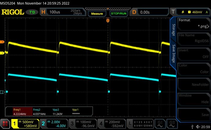
So far I always had a clean Sawtooth Waveform (SW) and assumed that all was well. But persistently L3 has not been making any difference to reducing input current, although it played a significant role in make the SW linear. Increasing or reducing L3 turns by just 3 or 6 made a huge impact on SW, so it was definitely strong enough.
The complete block in progress has forced a review from scratch. I went through many checks of which I offer a summary here.
Rechecking currents using the right-hand rule reveals that diode D3 is connected in the wrong direction, and so POC fields do not oppose. But connecting D3 correctly kills the SW. At a very early stage when I had checked this, I assumed the CCW somehow reverses the field. That was wrong.
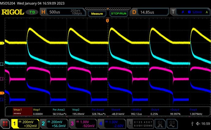
So how was I getting such a clean SW with wrong diode polarity and without coil opposition?
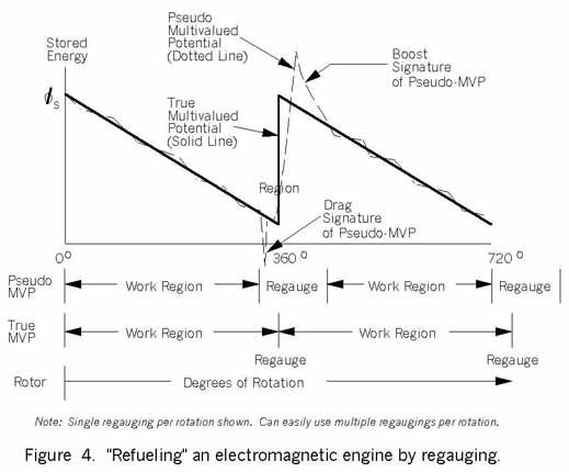
The answer is in Chris' post here: https://www.aboveunity.com/thread/the-sawtooth-waveform/?order=all#comment-25542b1e-aabc-453c-8083-ac8d001b8b05 where he compares the POC SW with the Flyback Converter SW.
Due to the wrong polarity of the D3, I just had built a very efficient Flyback Converter instead of a POC!
I'm documenting this in detail so as to warn others of making the same mistake. Getting a good SW is not enough! Ensure the correct polarity of your magnetic fields first, then aim for SW.
My sincere apologies to all for this serious lapse! And thank you Chris for your patience. I assure you, that I will more than make up for this mistake in subsequent work.
All that has been documented so far in this thread is now of limited value and perhaps partly wrong since there was no opposition in the coils. I thought of starting a new thread with fresh data. But in retrospect, I feel that the documentation of steps and learning experiences are all valid, including the consequences of such a basic mistake. And the thought process of exploration and validation will stand in spite of all else.
So I will continue on this thread with the necessary corrections that follow.
Diagnostic Mode
Getting L3 to oppose L2 is simple -- just turn diode D3. But this kills the SW and makes it flat. How to get back the SW, and then how to get it to support L1?
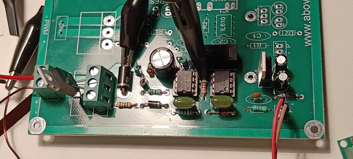
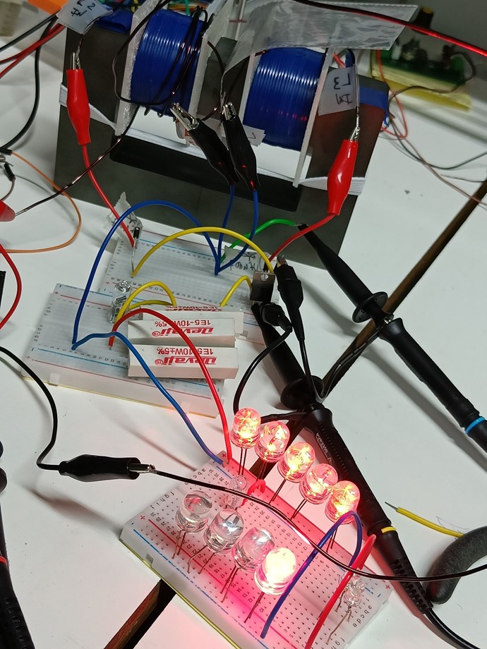
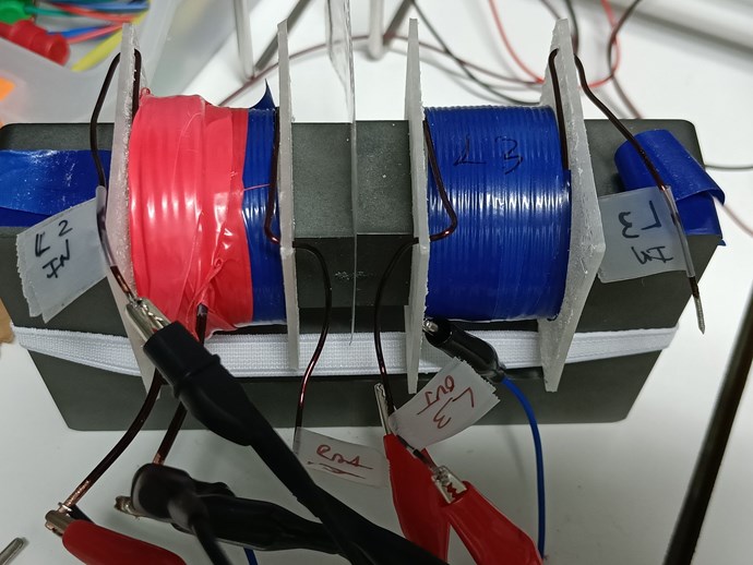
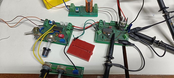
I placed the existing coils on the following circuit using a breadboard:
.jpg?width=690&upscale=false)
In this mode it is easy to isolate the effect of L3 on input current.
For purpose of consistency of measurements, I took an arbitrary pulse of F=1KHz, D=3%, V=6V and used about 1Ω 5W resistor as load. Also removed the 1000uF on L1 side so that the mechanical Ammeter on L1 is unbiased.
Unlike in the image above, I will refer to the POC components and measurements by the number of their corresponding coils. So D2, D3, I2, I3, V2, V3, etc. to maintain consistency across the thread.
Basic scope shots
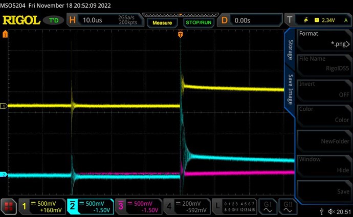
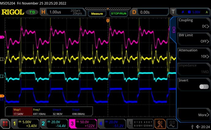
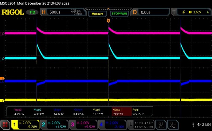
Below are the currents (Yellow=I3, Teal=I2) and voltages (Pink=V3, Blue=V2) on L2 and L3, which I origianally did with the wrong direction of diode D3:
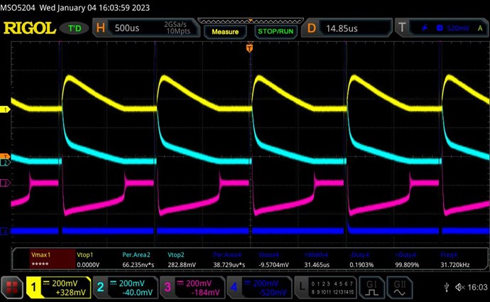
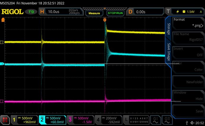
Below are currents (Yellow=I3, Teal=I2) with input pulse (Pink=V1, Blue=I1):
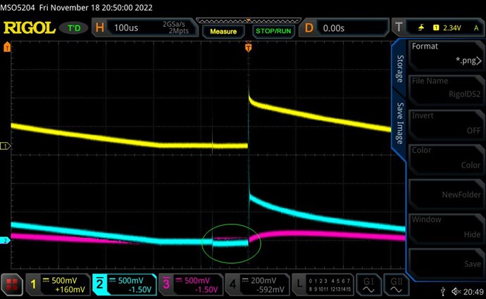
With diode D3 correctly directed we get:
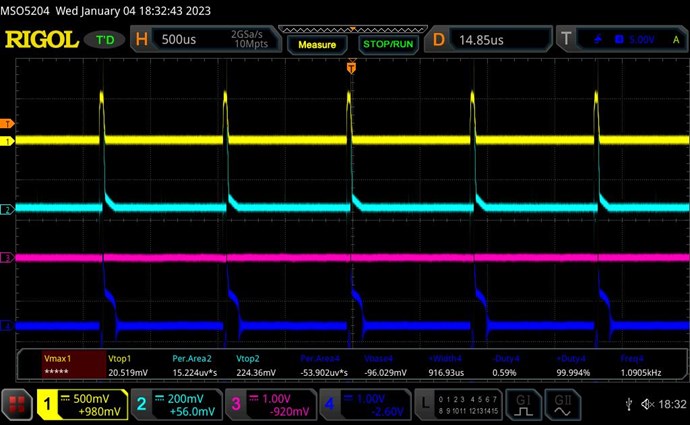
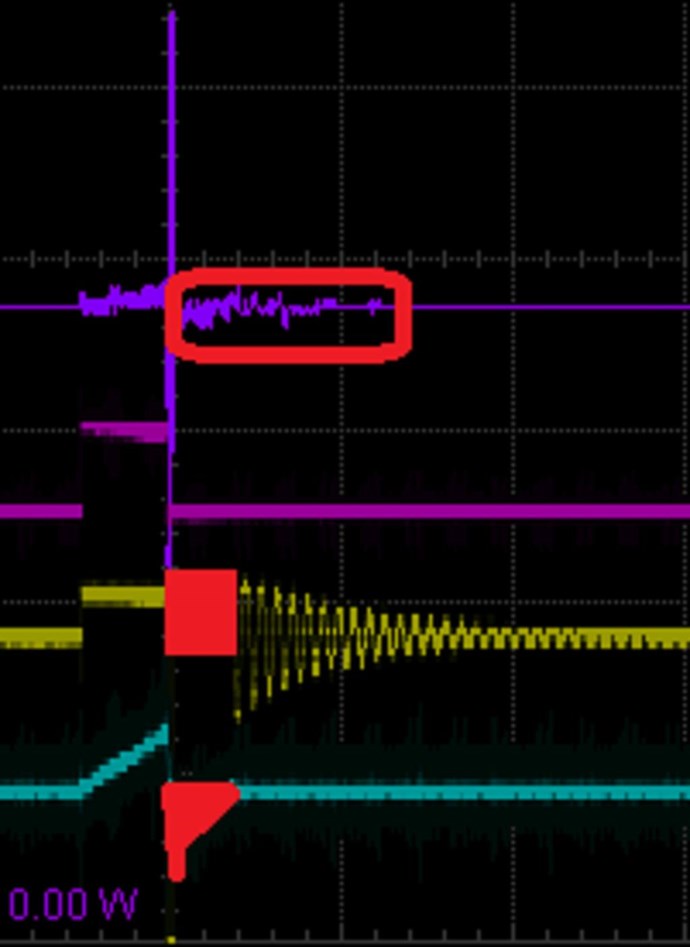
The little notch on the Teal line is actually a straight line! I totally missed seeing this the first time while trying out all combinations (before I realised my error).
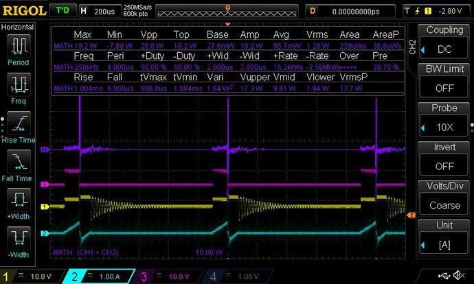
Input coil current is I1=80mA for D=3%. Raising the Duty Cycle to D=25% makes input current shoot up dramatically to I1=700mA, but the SW is clearer:
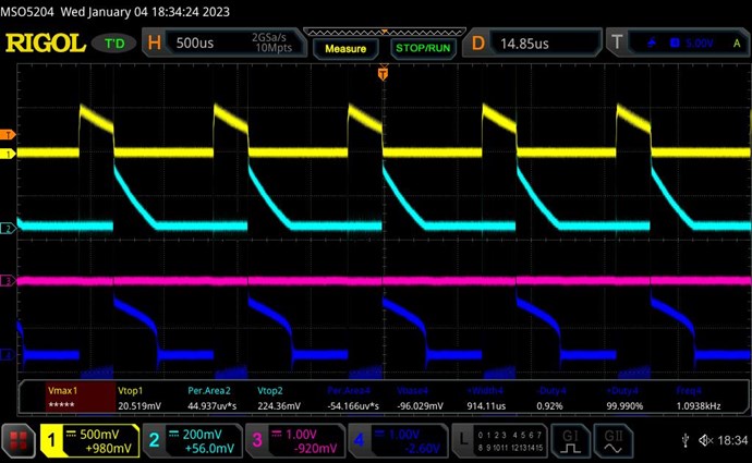
Now to check if input current L1 is supported by L3.
Removing L3 makes the L2 current rise and more like a SW, but the input current drops to I1=650mA:
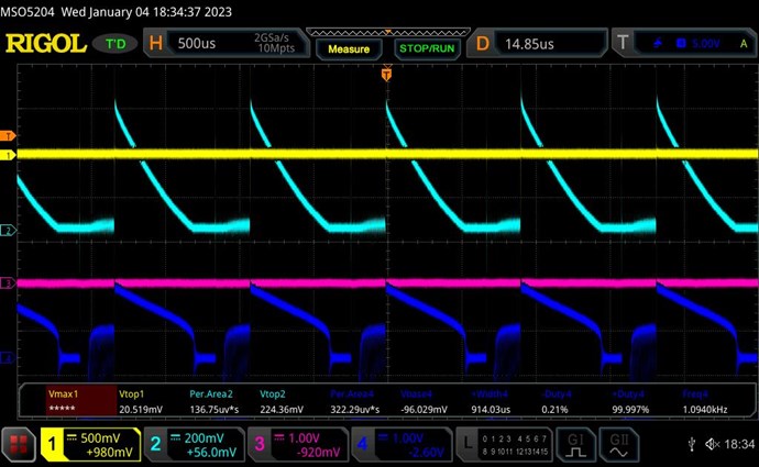
(Just to compare, with D3 wrong giving the Flyback Converter SW there is no change in input current with L3 removed or even with L2 removed.)
But with the correct diode direction and POC SW, the input current still drops when L3 is removed, instead of rising.
This means that although we have the POC magnetic bucking, the L3 coil is not yet supporting L1 coil.
I tried every possible combination of input/out and diode positions but could not get L3 to support L1 as we want it to, or as shown by Wistiti. So next I turned to the Wistiti's configuration.
Wistiti's Configuration
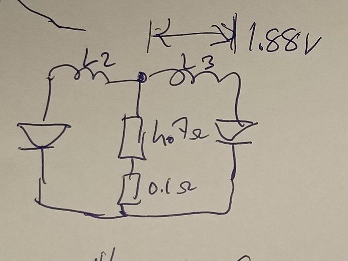
In his post and video at https://www.aboveunity.com/thread/some-coils-buck-and-some-coils-dont/?order=all#comment-92df39b3-7baa-4b4b-9d37-a88c00147dde, Wisititi offers this as circuit diagram:
.jpg?width=690&upscale=false)
Wistiti wires his L1 equally across both L2 and L3. So first I tried this, and immediately got the effect of L1 current reduction with L3 on. But L1 wrapped only on L2 for POC gave even better results which are documented here.
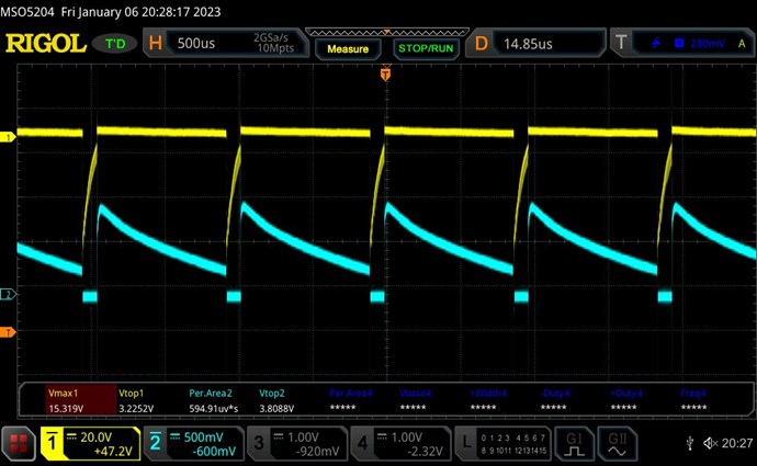
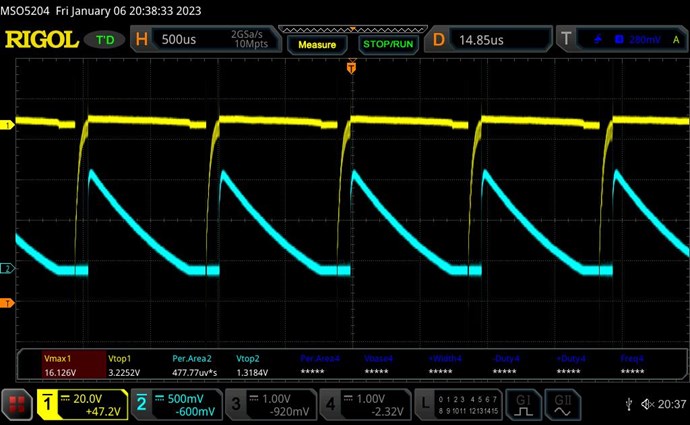
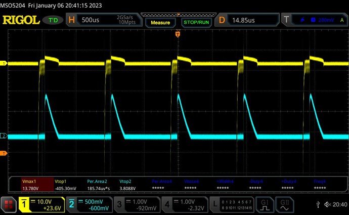
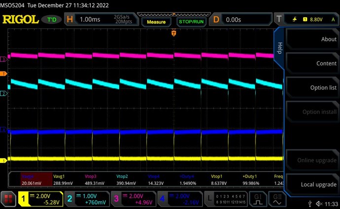
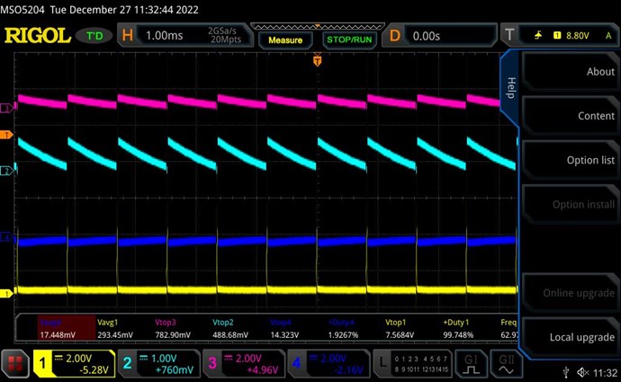
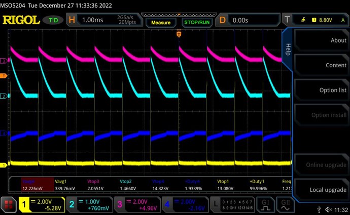
In the subsequent scope shots Yellow=Voltage and Teal=Current from coils output, and D3 is the diode at the centre of POC, and D2 is the diode at the extremes of POC.
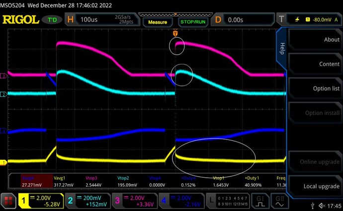
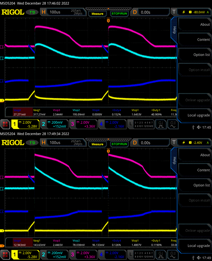
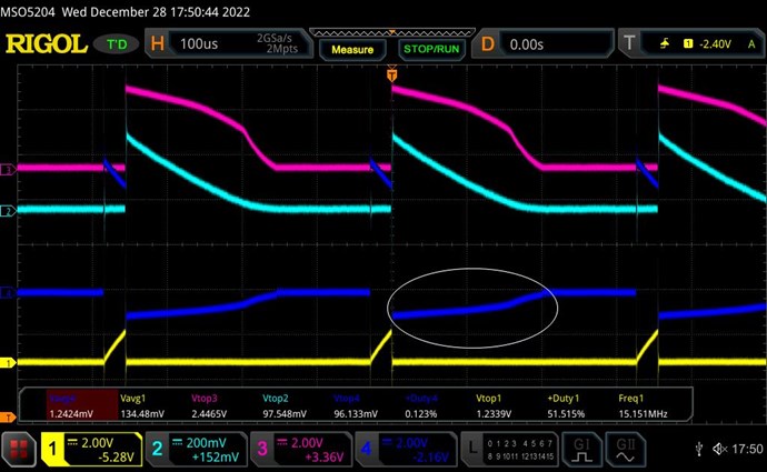
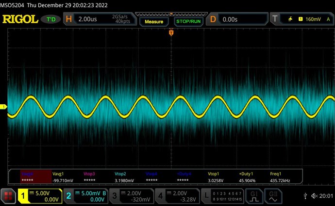
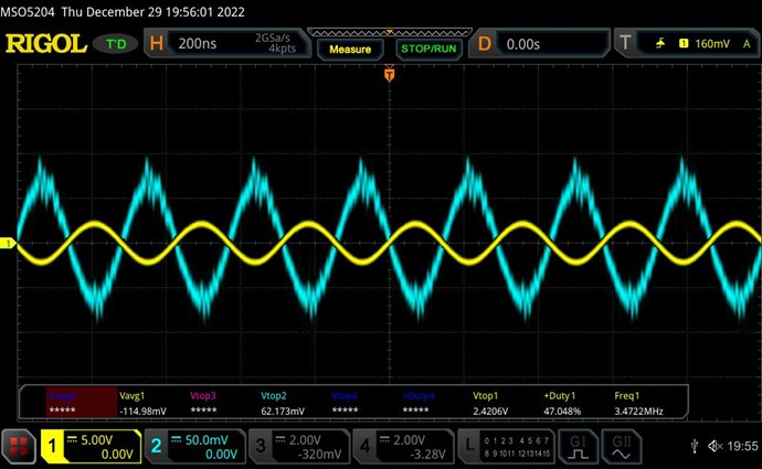
With correct positioning of both diodes the input current I1=320mA:
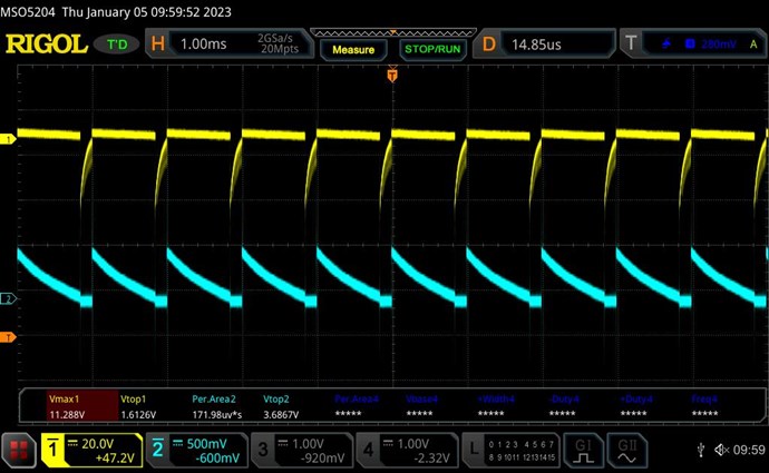
Shorting (removing) D3 correctly raises input current to I1=380mA:
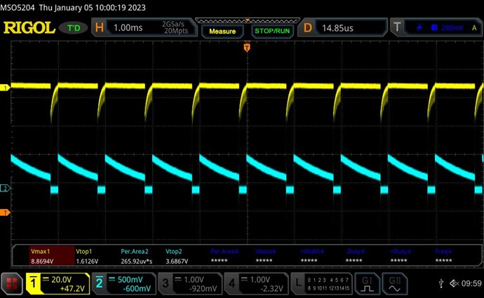
Shorting (removing) D2 also correctly raises input current to I1=380mA with similar waveform as above.
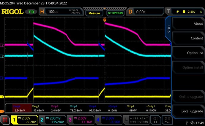
Shorting (removing) both diodes kills the SW and raises current the highest to I1=470mA:
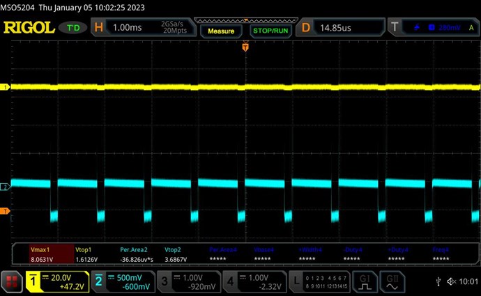
It is obvious that the POC did not get a chance to build up to opposition, and there is no current pumping effect.
Reversing both diodes raises input current to I1=440mA and without SW:
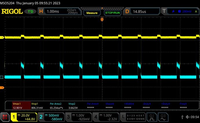
With reversed diodes, shorting one or both of the reversed diodes raises the current slightly more with I1=460mA with similar waveform.
Here I have successfully and entirely replicated Wistiti's experiment.
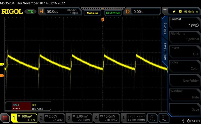
Straighening the curve
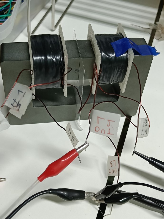
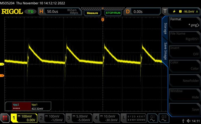
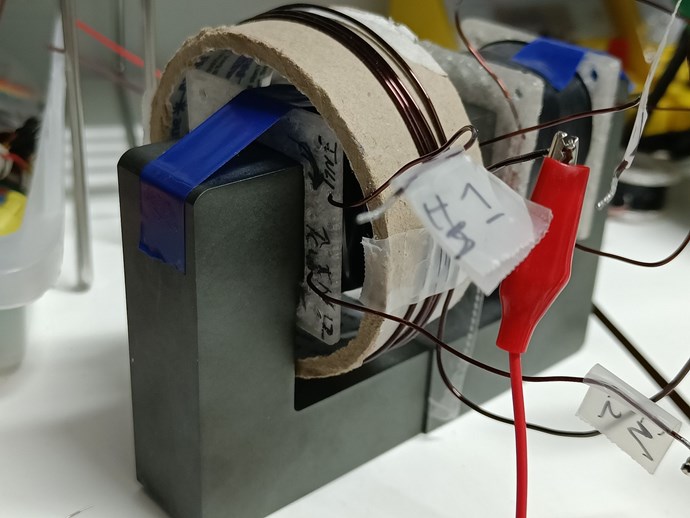
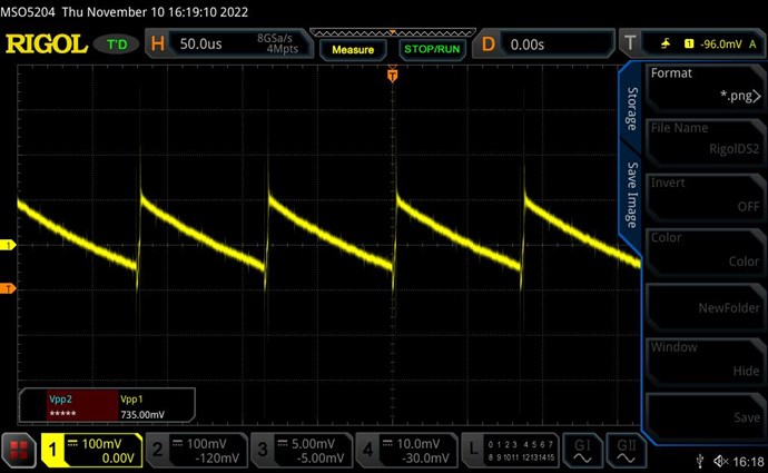
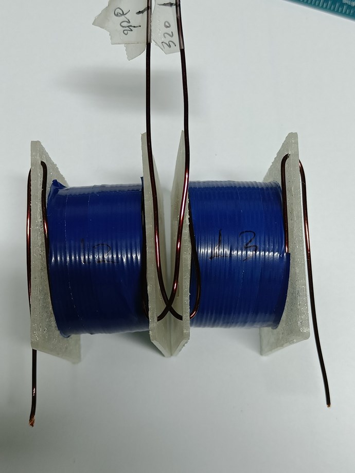
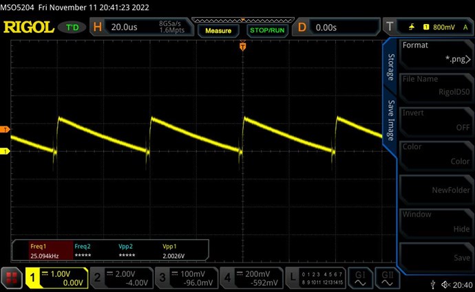
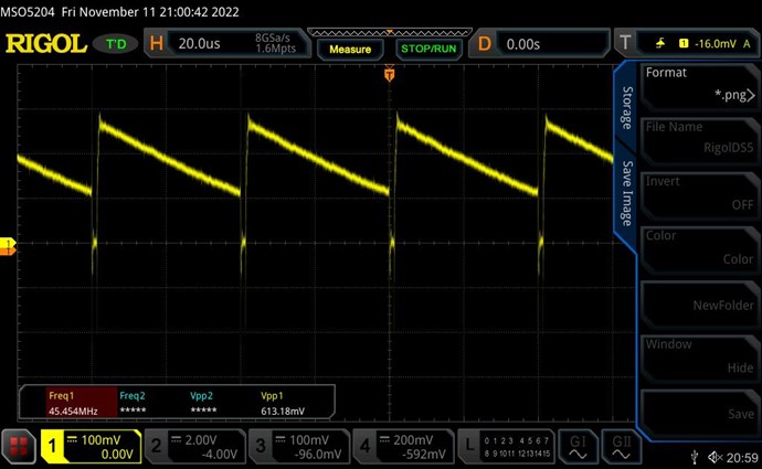
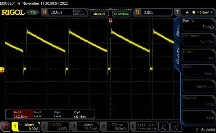
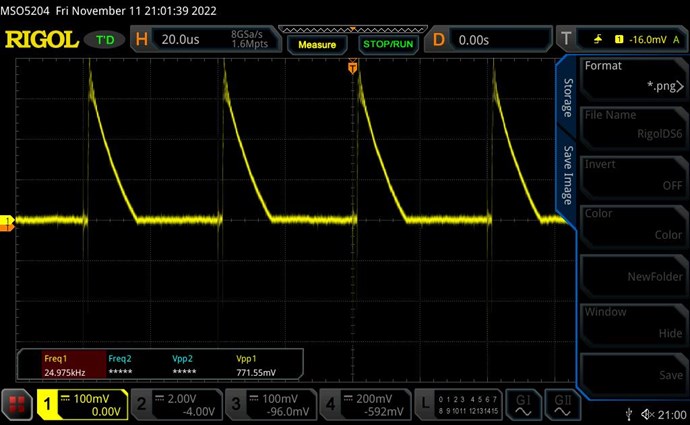
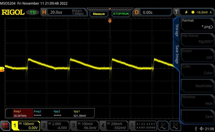
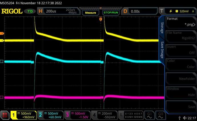
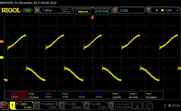
There remains one slight glitch. The SW is not yet a pure straight line. I realised that during the rearragement of coils, I had dropped the very thin piece of plastic from the gap between the cores. Re-inserting it gave the perfect SW:
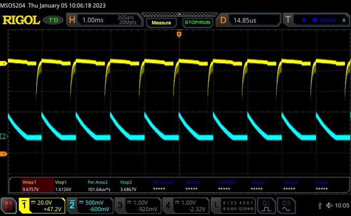
Some Thoughts
This result is deeply satifying. We have a clear and significant reduction in input current with full POC function.
The load configuration of Wistiti is very new to me, and I don't recall having seen it anywhere on this website.
What is very unusual is that shorting out any one of the diodes kills the effect of L3 supporting L1. In our normal way of thinking, a single diode on one side of the load would be the same as having both diodes on both sides of the load, especially since the load is a totally passive resistor. This is very strange and needs deeper thought.
The slight gap of core made a huge difference to the SW linearity. This will now be my reference for optimum core gap -- linearity of SW! The plastic piece is 0.065mm measured by micrometer. Putting a 1mm piece made the SW very narrow and slightly distorted.
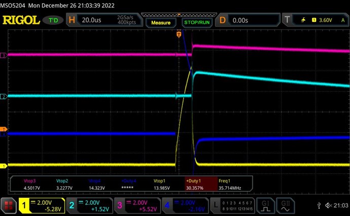
This configuration is still too new, and I will have to explore is further to get a "feel" of how the coils behave in this. But what I find promising is that the peak voltage on SW is already 3.6 volts for an input pulse of 6V. This means scaling up will be much easier and the input drop much more rapid.
At this point I have succesfully corrected a major mistake that had taken me off track, and now feel confident of further progress.
I'm actually surprised at the ease with which I was able to get all the effects once back on track, and can better appreciate Chris' frustration when people don't get it. I hope that my detailed documentation here will make it easier for many more to replicate as well as avoid the most common pitfalls.
This is very exciting and promising, and I look forward to playing with this configuration and reporting progress soon.


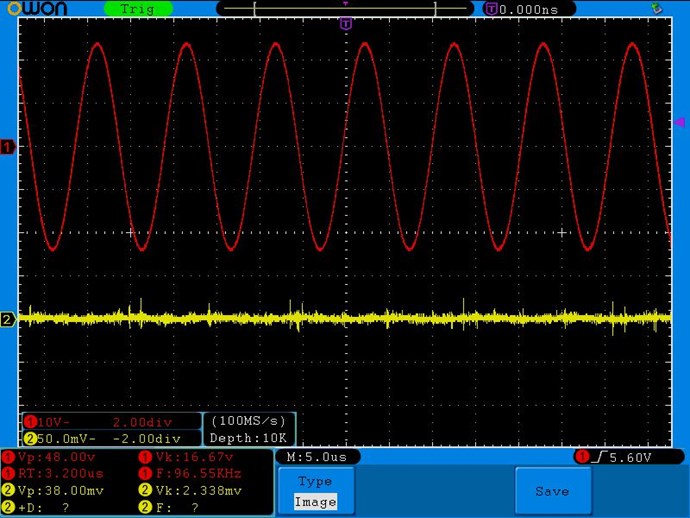
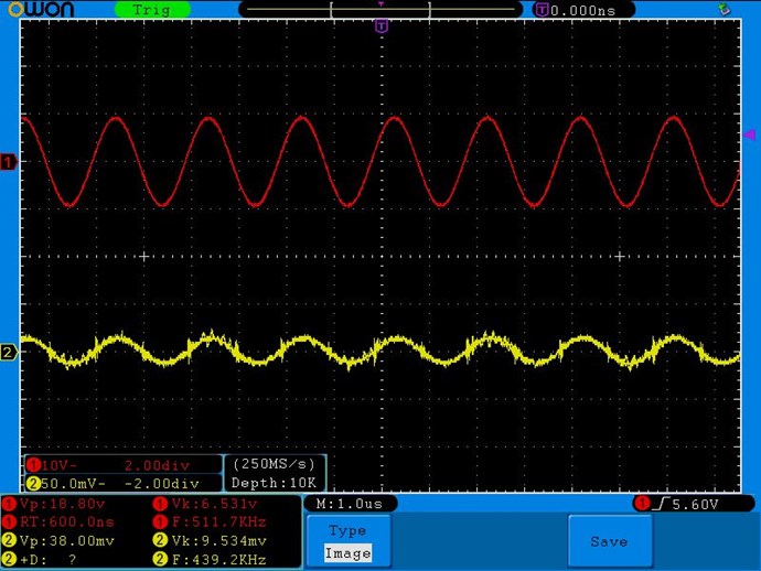
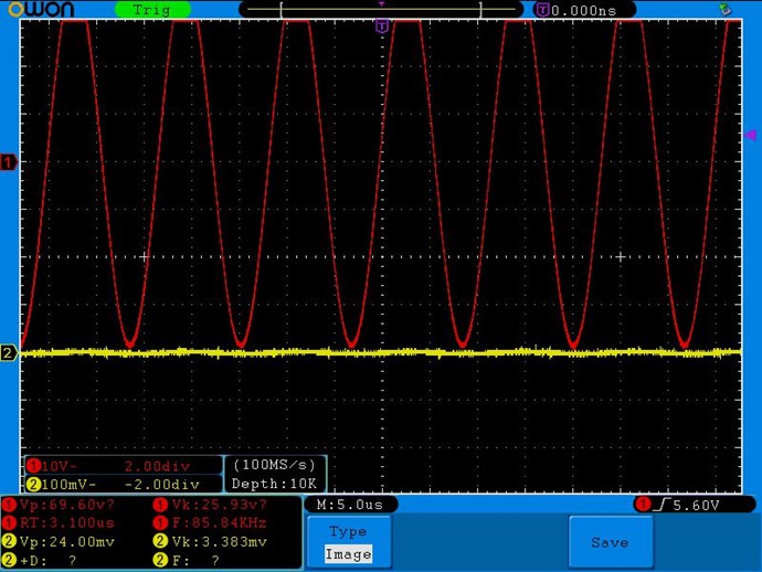
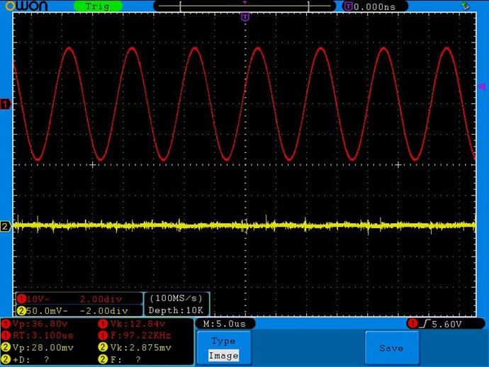







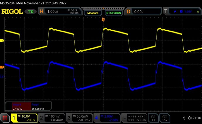
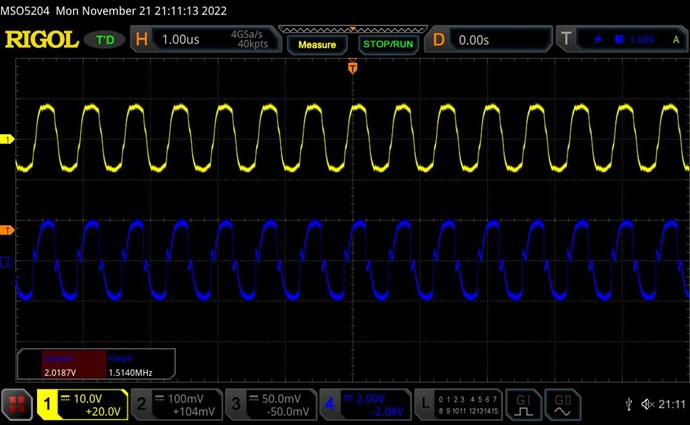
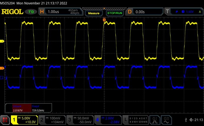
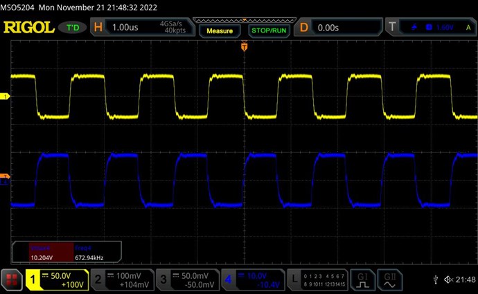




.jpg?width=690&upscale=false)


.jpg?width=690&upscale=false)


