Keep on Keeping on My Friend! ... so yes, you're on the right track and always have been.
Thank you for your encouragement Chris!
I've made more progress, but this time I'm taking smaller intermediate steps and observing variations in detail.
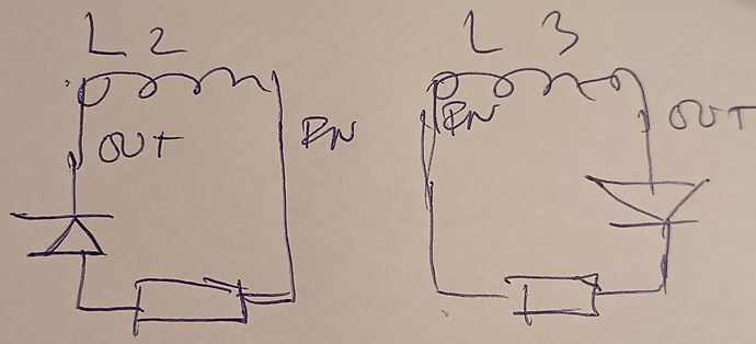
The new coils are:
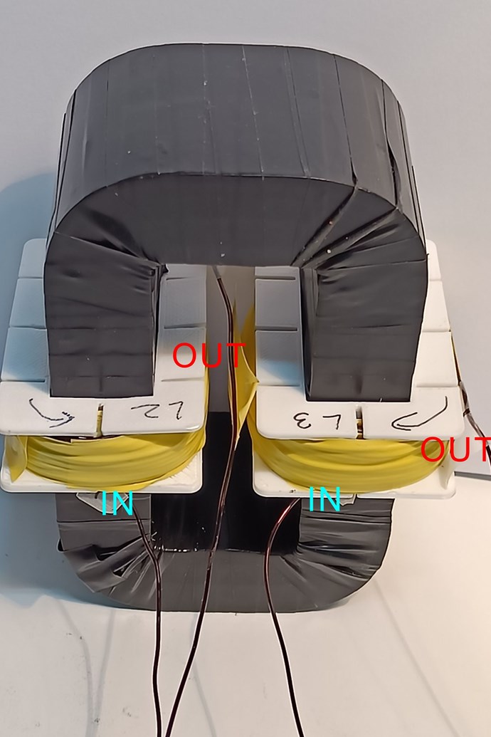
Coil Measurements
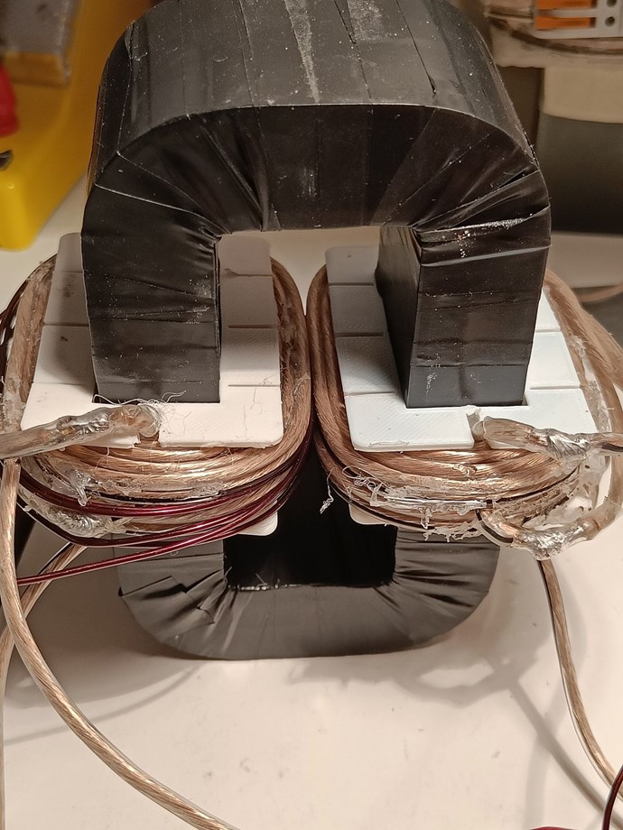
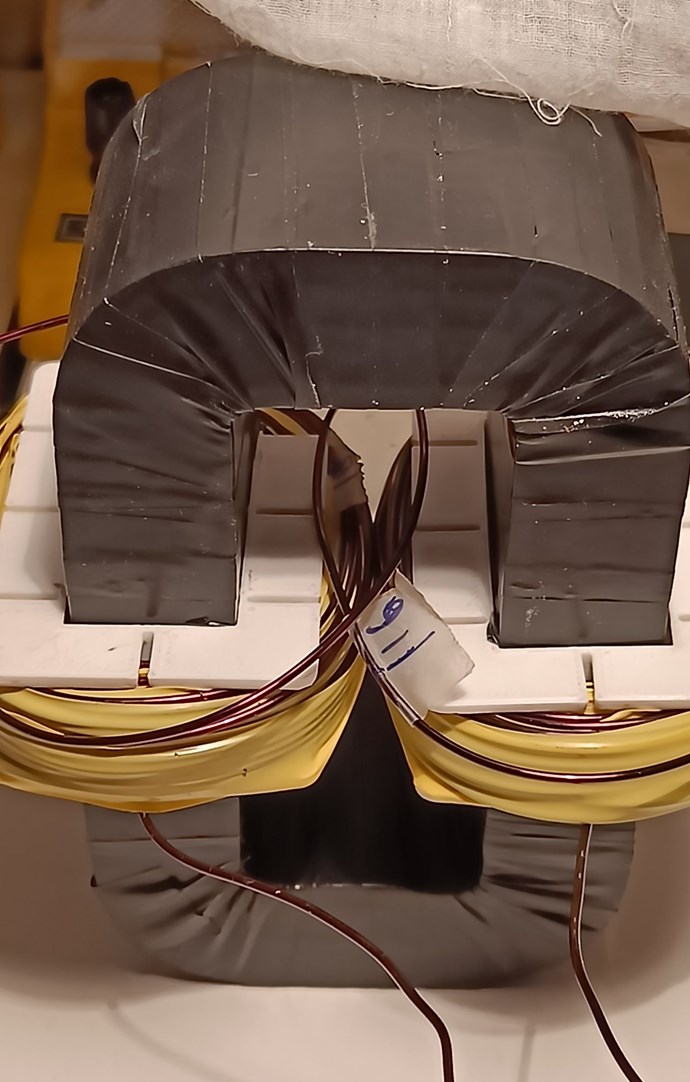
Both coils are 16m wound +0.3+0.3 leads of SWG 20 wire with 6.5 layers of 88 turns wound bottom to top only on each layer with insulation tape between layers. The first layer has 14 turns and most others are 13. I've mirrored the exact same count of turns on each layer in both coils. One quarter turn is used to bring the wire back from top to bottom without sharp turns so that the next layer can wind bottom to top again. Sharp turns are only at entry and exit from coils.
After winding, L2 had 7cm extra (half a turn extra) to complete the 16m length. Either L2 was wound tighter or it stretched a little while winding, or both.
L2: 88.5 turns CW. 0.5Ω, 489uH on air, 9.19mH on AMCC core.
L3: 88 turns CCW. 0.5Ω, 477uH on air, 8.82mH on AMCC core.
Finding Resonant Frequency
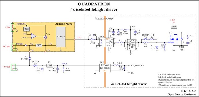
Following the method Chris taught here I tested every possible configuration for input and output, observing induced voltages and currents. The Signal Generator (SigGen) puts out 10.2Vpeak (20.4Vpp) Sine wave which was successively fed to L2 IN then OUT (see notation in image above) and then to L3 IN and then OUT, swapping the V and I measurements on the other coil for each case -- 8 configurations in all with multiple resonance F on each.
Only 4 of these configurations have magnetic fields opposing, and as expected these had the highest voltages of about 20V at about 207KHz. In all configurations there were at least two resonance points with the higher one being in the 700KHz to 800KHz ranges varying on exact frequencies in each configuration with output voltages ranging from 5V to 14V -- but nothing consistent.
Surprisingly there were two configurations in which magnetic fields were not opposting, yet the voltage was nearly 20V at F about 720KHz. The common feature of both these was that the SigGen was feeding the signal at the OUT end of the coils. Feeding signal at the IN end of the coils was consistently the worst.
Of the 4 valid configurations, the best results were when the SigGen was feeding OUT and the voltage measurement was on OUT of the other coil giving 21V each as opposed to 18.5V or so when SigGen feeds the IN and voltage is measured on the IN. All these are with conventional direction of current.
1: SigGen on L3IN gives 18.2V on L2IN at 206KHz
2: SigGen on L3OUT gives 21V on L2OUT at 208KHz
3: SigGen on L2IN gives 18.6V on L3IN at 209.7KHz
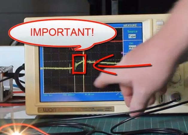
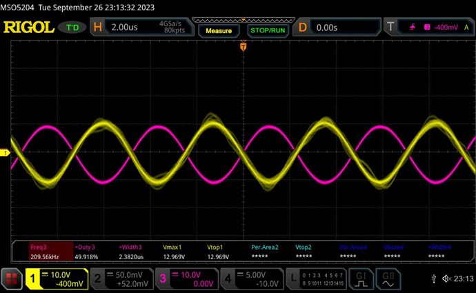
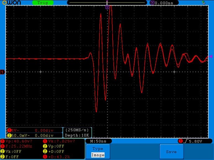
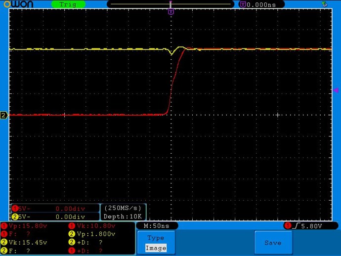
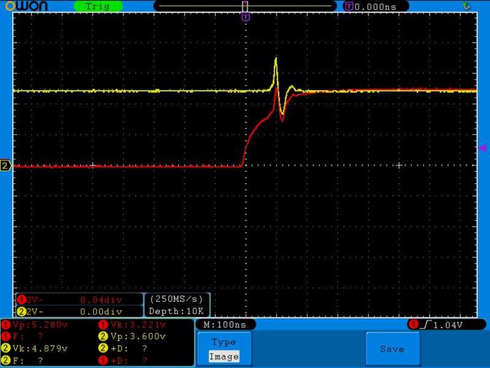
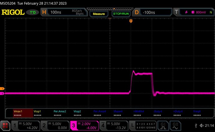
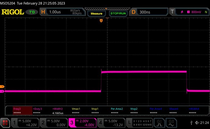
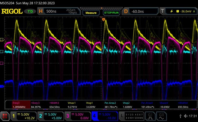
4: SigGen on L2OUT gives 21V on L3OUT at 209.3KHz (image below)
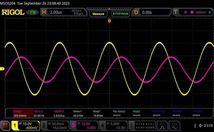
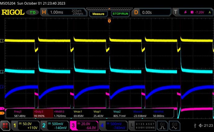
Pink = SigGen voltage, Yellow=POC voltage
The obvious conclusion is that the electron flow must enter the IN for best results. In all such cases the output voltage was nearly double of the input voltage.
Unusual obervation
I accidentally touched the open end of the input coil wire and the waveforms changed thus:
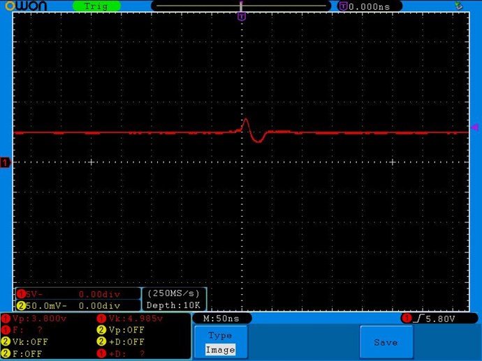
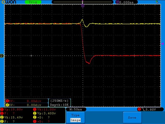
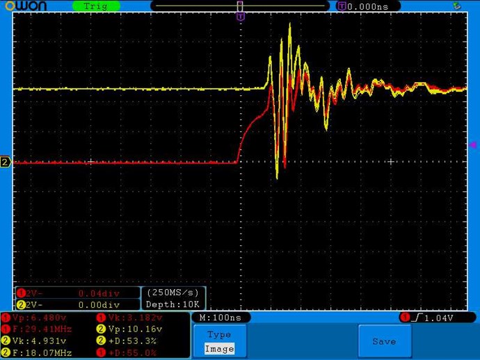
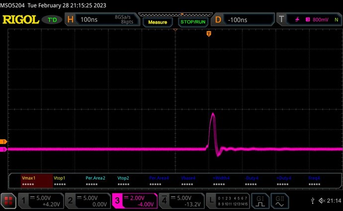
a) in the case where the two coils opposed each other, touching the open end caused the output wave to collapse and match the input:
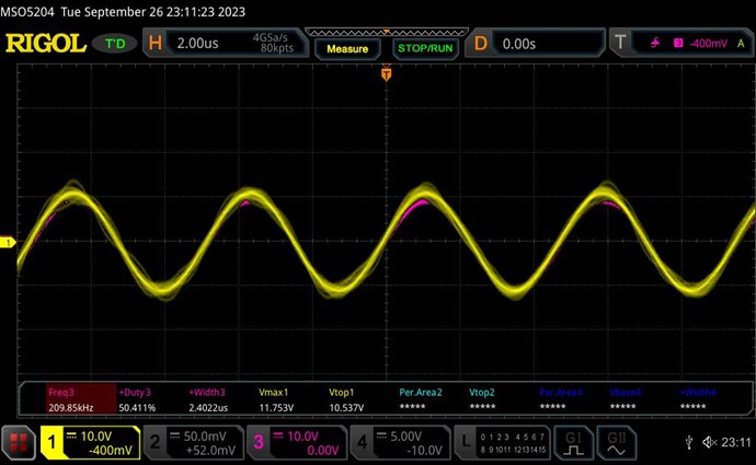
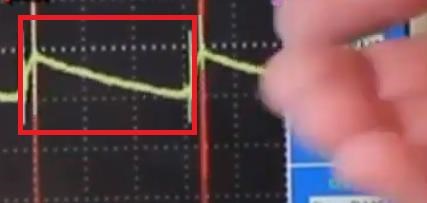
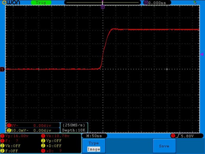
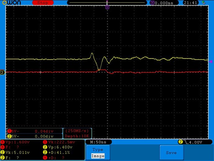
b) in the case where the two coils do NOT opposed each other, touching the open end caused the output wave to shift 180° out of phase with the input and with nearly the same height:
I don't know how to interpret this, but I'm leaving this as an observation, in case anyone can explain.
Adjusting the Resonant Frequency
There is some variation in the F depending on which end of which coil we feed. I thought this might be due to the L2 being half a turn longer. So I tried to reduce L2 by removing the half turn or increase it by completing the turn into a full turn, while feeding the signal on L2 then on L3. I had expected that the peak resonant F would not change when feeding signal on L2 since the peak voltage depends purely on L3's resonance value which should not change as I did not change its coil length.
But surprisingly I found that in all cases the resonant F changed when L2 was changed, but in different ways:
a) When feeding SigGen to L2, and reading on L3: increasing L2 length (from no extra turn to full extra turn) increases F by about 2.5KHz.
b) When feeding SigGen to L3, and reading on L2: increasing L2 length (from no extra turn to full extra turn) reduces F by about 1KHz.
So it seems the peak resonant F is formed by some interdependence between both coils. Winding them to exactly mirror each other is therefore very important to get the best magnetic resonance!
The exact F was varying slightly each time because the long wire leads moved too much (30cm leads seem to be tool long!)
I finally decided to remove the extra turn. Both coils now have exactly 88 turns. But L2 winding is shorter by about 7cm.
Preliminary Pulsing of Coils
Taking F=207KHz as an average, should give a wave duration of 4830nS or 4.83uS, and a quarter wavelength of 1.2uS. This value is for later use.
As a preliminary test, I loosely wound 4 turns of L1 around L2 and pulsed at 1.5V at 1.2Khz and 10% duty cycle as arbitrary values keeping both L2 and L3 in separate circuits and measuring currents in each using the 0.1Ω resistor.
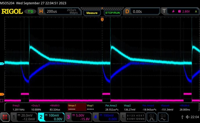
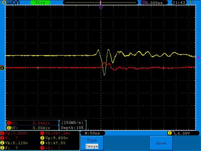
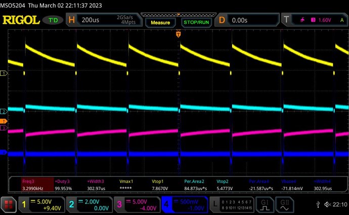
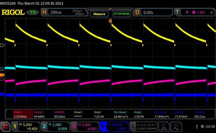
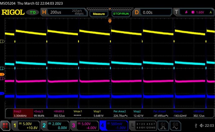
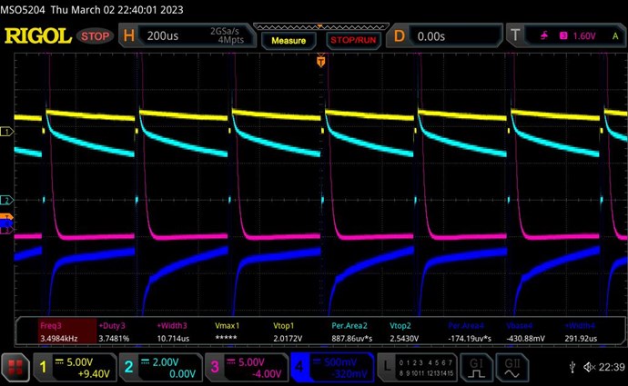
The currents in both coils seem similar and mirrored, although L3 is slightly lower by about 15%. L3 also has a clear curve of current build up during the pulse, but L2 does not show such a build up. In the following images: Teal = L2 current, Blue = L3 current, Pink = pulse signal.
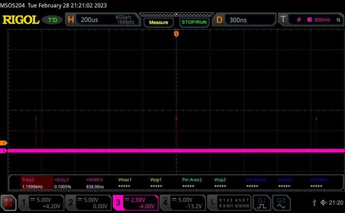
At 10% duty cycle (83uS pulse) the input of 1.5V drew 0.39A:
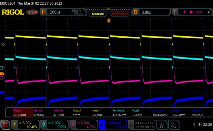
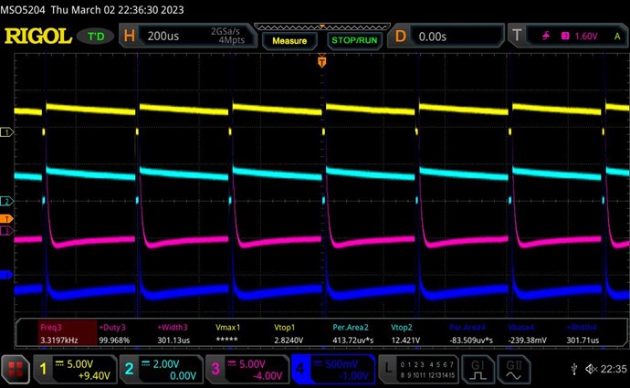
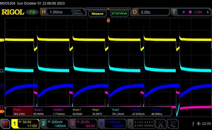
At 8% duty cycle (66.7uS) the input of 1.5V drew 0.3A:
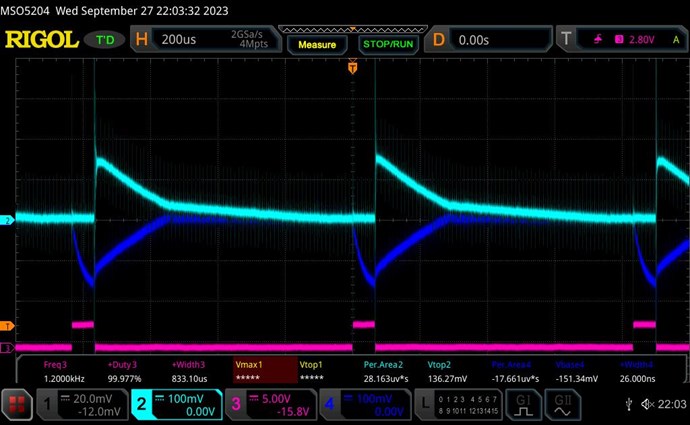
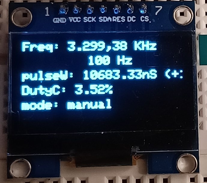
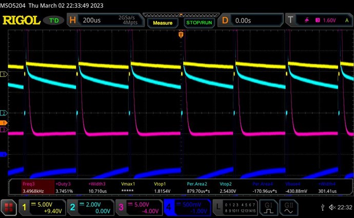
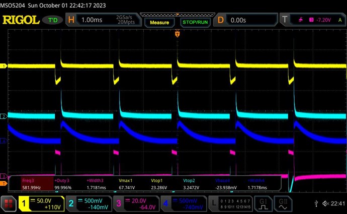
At 2.97% duty cycle (24.7uS) the input of 1.5V drew 0.09A (a sudden and disproportionate reduction):
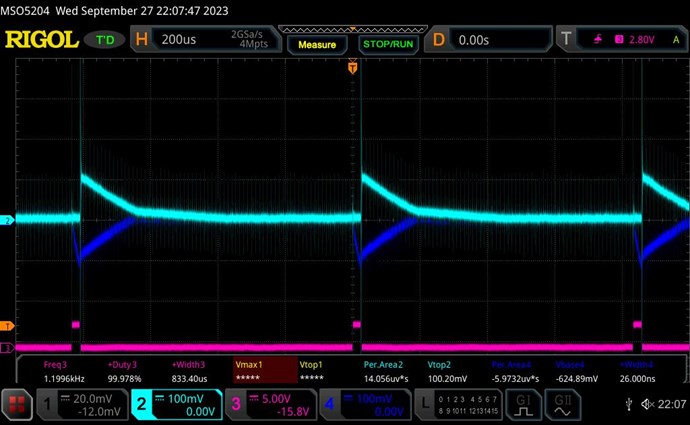
The change in the charging curve in L3 is interesting to notice. Raising above 12% duty cyle makes this curve turn back towards zero and both currents drop rapidly as duty cycle is further increased.
Next Steps
Next I plan to:
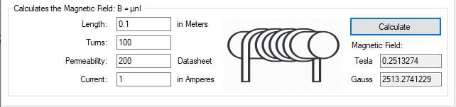
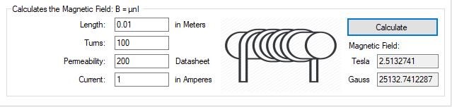
a) wind L1 tightly and with the correct length from suitable calculation.
b) recheck if resonant F has changed.
c) cut out excess lead wire if needed if it affects resonance F too much. Need to get F to be as stable as possible.
d) pulse at the correct F and D calculated from the resonant F.
e) rewire L2 and L3 circuit to drive a load separately or jointly. I'm not sure how to wire them to jointly run a single load. Any advice would be appreciate, @Chris.


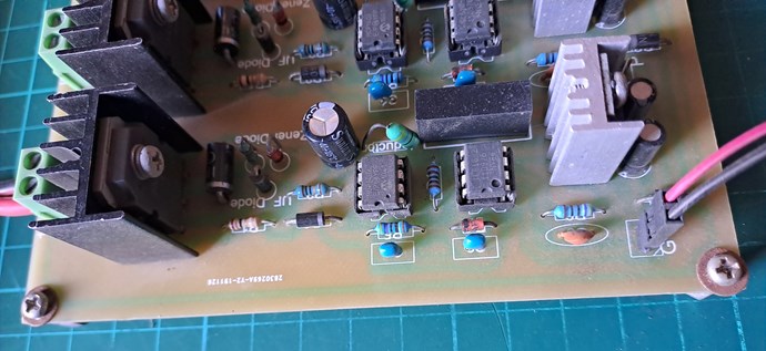
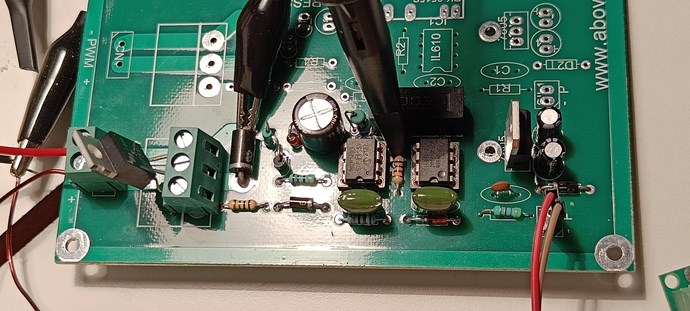


 , and hence to be replaced soon. Or perhaps it comes from placing the MOSFET through a connector block like this:
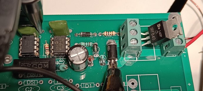


 , and because we have a Load, a Current ( I