ISLab maximising magnetic resonance in POC

  • 4.2K Views
  • Last Post 09 October 2023
ISLab posted this 04 November 2022

In my previous thread on ISLab's Replication of Basic POC Effect, I had many useful learning outcomes and got a good "feel" for the behaviour of POC coils under various kinds of situations. With help and encouragement from all of you, I was able to get the Sawtooth Wave and "generate" more power than "induced" within the coils.

This thread will focus on optimising the POC coils and maximising their magnetic resonance for optimum power generation.

Order By: Standard | Newest | Votes
ISLab posted this 07 November 2022

In this thread I will only be using large C-cores. I had already wound coils for this back in February. These are not optimal as my understanding has grown much since then. But I will use these for an initial study of magnetic resonance before winding better coils as a subsequent step.

What follows below is the study of magnetic resonance in these non-optimal coils.

The coils are:

L1: 29.4uH (in air), 2.6mH (on core), 0.3 ohm, 20 SWG, 24 turns, 378cm, CW.

L2: 0.376mH (in air), 49.4mH (on core), 0.6 ohm, 20 SWG, 104 turns, 1470cm, CW.

L3: 0.372mH (in air), 49.4mH (on core), 0.6 ohm, 20 SWG, 104 turns, 1461cm CW flipped.

Testing them for magnetic coupling coefficient shows:

KL1-L2 = 0.994

KL1-L3 = 0.763

KL2-L3 = 0.757


The cores with coils set up for measurement of magnetic resonance:


I decided to test magnetic resonance in all possible combinations just to see if it made a difference. And it did!

With a core separation gap of about 1.1mm there were two peaks of resonance, one around 185KHz and one around 500KHz.

Reducing gap to 0.1mm also gave two peaks but both became much narrower, rising suddenly and dropping suddenly within ± 2Khz. But it did not change the peak voltages by much when at correct frequency.

Below is the table of measurements for 0.1mm gap:


L2 IN and L3 IN are where the coil windings begin on the first layer of the coils, and L2 OUT and L2 OUT are where the wires exit the coils after winding the topmost layer. All layers are wound asymmetrically in a single direction left to right, then straight back, and again left to right, etc. L3 is flipped and exactly mirror image of L2 when placed on the cores.

The variations of F between measurements seem to be due to slight movement of coils on the core due to wire tension, showing how critical it is to completely lock down the wires and coils on the core. When hitting resonance, there is a significant reduction in peak by nearly 50% with F just 1KHz off from peak for core gap of 0.1mm; the variation is much less when core gap is 1.1mm.

Scope photos referred in the table follow:

Photo 1


Photo 2


Photo 3


Photo 4


Photo 5


I was surprised that the coils don't work the same both ways. Perhaps because these coils were wound asymmetrically, or perhaps dues to point of entry on layer. Maybe if the windings were left-right right-left as people normally do, it might be the same; or perhaps not if the difference is caused by point of entry being on lowest or highest layers.

Strangely though, I could not get the currents to be 180° out of phase -- they seem to be nearly exactly in-phase. (In a prior test in my previous thread with E-cores the current was obviously 180° out of phase.)

In showing how to test for magnetic resonance Chris had said to pick the F that gives the highest voltage.

In this case the highest voltage is in Photo 3, but the currents are very low. Photo 5 gives the best combination of voltages and currents. My logical thinking would point to this as better configuration. But is that correct?

Questions to Chris and team:

  1. Why don't I see the currents 180° out of phase? Is it actually out of phase but displaced too much dues to other reasons? Is this critical if I've actually found the best voltage and resonance anyway?
  2. Should I aim for highest voltage (at 82Khz) or best combination of voltage and current (at 486KHz)?
  3. In general, is it better to use the lower F if the two frequencies give similar results?
  4. Is it better to increase core gap slightly to make the resonance F less intolerant to slight variations (since peak voltages are similar anyway)?

Any advice and guidelines will be much valued. Thank you! 😁

Chris posted this 07 November 2022

Hi ISlab,

All Valuable Experiments, but...

I think you've gone off on a bit of a tangent, missing the point of: Chris's Non-Inductive Coil Experiment


Of course, the Forward Mutual Inductance, will create an In Phase condition in the Coils, there will be no Opposition of Partnered Output Coils.

Maybe reviewing my Thread and videos will help. 

Best Wishes,

   Chris

  • Liked by
  • Augenblick
  • strape
ISLab posted this 08 November 2022

Hi Chris,

>>you've gone off on a bit of a tangent, missing the point of: Chris's Non-Inductive Coil Experiment

I've already done a quick test and easily got the Sawtooth Waveform (SW) on this coil. To post that as is would add nothing new as insight or progress. My intention here is to explore the magnetic resonance in greater detail to understand its parameters so as to increase and optimise it. Then I will post the SW output with the "before" and "after" of the improvement.


>>Of course, the Forward Mutual Inductance, will create an In Phase condition in the Coils

This is new to me. So far I assumed that any magnetic resonance would produce out-of-phase current. What this means is the magnetic resonance can take place in many modes; we have to find the modes in which the current is 180° out-of-phase and then pick the one with the highest voltage. Is my understanding correct?

[Edit:] In your video "The Secret Revealed -- Resonance Magnetically" you demonstrate this resonance on your coils at about 3MHz, then you say that this is a harmonic of the actual resonant frequency which you show to be about 132KHz. but at this point you don't show the current, nor explain why you did not stay with actual frequency and went with the harmonic instead. Could you please elaborate this? This seems to be very important and deserves fuller discussion.

Thank you!

ISLab

Chris posted this 08 November 2022

Hi ISlab,

Magnetic Resonance is seen very clearly at the part marked Important:


Which must be tuned for optimum efficiency.


EDIT:

Not forgetting the definition I have laid out for Magnetic Resonance:

Magnetic Resonance is where the Currents in both Partnered Output Coils are 180 degrees out of phase. Equal in magnitude and opposite.

Ref: Magnetic Resonance


Best Wishes,

   Chris

ISLab posted this 09 November 2022

Method of finding magnetic resonance is as described in Chris' video:

My oscilloscope was limited to 30MHz, and its sensitivity was limited so that I could not see the low value currents in the previous post, and so got side-tracked to the 0° in-phase readings which alone were visible.

Taking my coils to a more sensitive oscilloscope I get the following results:

Photo1:

Photo 2:


Observation 1:

There are two frequencies of resonance: about 82Khz and about 510KHz. The 82KHz never gives any useful current in L3 during resonance. The 510 KHz gives good current which is 180° out of phase when voltage is measured on L3 IN (with L3 OUT grounded), but gives 0° phase when voltage is measure on L3 OUT (with L3 IN grounded).

Surprisingly, where I put the Signal Generator (L2 IN or L2 OUT) makes no difference to the phase shift in L3! It only makes a difference to the peak voltage which is at least 50% higher when Signal is on L2 IN.

Observation 2:

So I put the Signal on L1 and tried, getting the same result and almost the same F of resonance. Here the best voltage is with Signal on L1 OUT, and no clear current with Signal on L1 IN, although with good resonance. Swapping measurements on L3 gives 0° phase as before.

This is was very surprising at first. But it makes sense if L1 is inducing in L2 which is then resonating with L3 as before, and would explain why the inputs need to be swapped on L1.

Observation 3:

Swapping L2 and L3 gives the same result with same frequencies: 180° when measuring voltage on L2 IN (with L2 OUT grounded), and 0° when measuring voltage on L2 OUT, independent of where Signal is injected in L3. And the lower F gives no measurable current.

Observation 4:

Placing Jagau's SRO on L2 gave F=42KHz unstable, and on L1 gave F=104KHz. Neither gave any meaningful output on L3 which was hooked up as before. This is to be expected as most likely these frequencies represent LC resonance and not magnetic resonance.

Observation 5:

Flipping L3 around on the core, sitting in the same place, reverses the relationships for phase. Now I have 180° phase with voltage measured on L3 OUT (with L3 IN grounded).

Flipping L2 around changes nothing on L3 output phase, but flips the side which gives the highest value of Vpp is now measured when the Signal is on L2 OUT.

Observation 6:

In all these changes of Signal point and measurement points, the Resonant F changes very slightly, within 10KHz, but not because of coil movement as the coils were fixed firmly. Shifting the coil on the core by about 1/2 of its length shifted the resonant peak by about 7KHz. So it seems the changes are due to the entry point of current shifting from one end of the coil to the other when inputs are swapped.

Observation 7:

To maintain 180° phase shift when a coil is reversed we need to swap its leads. Hence the 180° phase depends only on the placement of the Ground in relation to the core and the other coil. The current is AC so we cannot speak of it as depending on the direction of the current. But it is intimately linked to the direction of coil winding. In this case it is the magnetic pole pointing to the centre which stays constant (for the given winding which is CW). Will it be the reverse if the winding were CCW?

Keep in mind that some of these observations would be specific to the peculiar asymmetric winding that I had on these coils (described in previous post). But other observations should be common to all coils.

Observation 8:

The slightest touch of hand or pressure on the core shifts the peak of F radically. As also position of coils on the core, and slight shifts of coil angle if the coil is loose.

Conclusions:

  • Coil winding direction and length are critical to magnetic resonance.
  • Placement of coils on the core, pressure of core, gap of core will all affect the peak F of resonance. Hence the need to fix all these rigidly.
  • Magnetic resonance is independent of LC resonance frequency which can be quite different.
  • Finding the magnetic resonance F requires you to scan to much higher frequencies. But pulsing L1 can be on a lower Fn which is divided F divided by integer N and with Duty Cycle also suitably divided by N.
  • Many of these observations make more sense when we view the POC coils as the two lines of a dipole antenna which have been wound up. But now each turn of the winding is also an antenna to the other turns. So winding spacing, wire enamel thickness or wire insulation thickness and type would all make a difference to the resonant F.
  • It is not obvious which side of the coils would give the best voltages or currents, hence it is better to try both sides of each coil, in every permutation and combination for optimal output.


Chris posted this 10 November 2022

Hello ISlab,

Let me drop this in your Lap: "There is a Natural and also an Induced Resonance"

Frequency can be 10Hz or 10KHz depending on factors I will discuss later!

This topic will be discussed further at a later date! I will not be discussing more until then!

Best Wishes,

   Chris

ISLab posted this 10 November 2022

>>This topic will be discussed further at a later date! I will not be discussing more until then!

Noted. I hope it is ok with you that I continue to post my explorations on this though. Please let me know if you prefer that I don't post on this aspect. Also feel free to comment on other aspects of these explorations.


Continuing my explorations with the non-optimal coils

Started with rechecking the optimal F which was found to be 513.5KHz. Then connected the POCs the usual way and pulsed with F at 50% duty cycle and progressively less.

There was no useful waveform and no Sawtooth Waveform (SW) on the POC output. This I take to be because F is too high for L1 to induce in L2. Quick test shows F needs to be below 40KHz to get any useful induction from L1 to L2, and ideally below 25KHz.

I had expected that there will be some precise frequency F / N (where N is an integer) where I will suddenly get much better output. This was not the case, although I think I was able to tune quite closely to F=10.27KHz (which is 513.5 / 50). Duty cycle was reduced proportionally to some 2%.

In practice the entire range from 10KHz to 25Khz gave a nice Sawtooth Waveform (SW), peaking around 10Khz, and then losing the clear triangle and becoming curved as F drops below. For optimum SW, we need F > 10 KHz with duty cycle of maximum 3.5%.

But this did not come at first. At first I got a crooked SW (as below).


This was because the contribution of L3 to SW was so low that the diode was cutting off the bulk of it. Removing the diode completely from L3 (shorting it) gave a clean SW:


Separating the coils up to 1cm made no difference to the SW, but only lowered the peak by about 10%.

Raising the pulsing voltage required me to reduce the duty cycle further to allow SW to fully use up. So it seems I have reached the limit of what these coils can generate.

Now I have two limitations to overcome:

  • L1/L2 induction needs to be *much* more loose and free to allow easy response to higher F. Remember, even if I keep a low F and low duty cycle, effectively the pulse induced will have to be of the duration of a 513.5KHz pulse. So in practice I still need a high frequency response in the coils to get a clean short pulse to act on the POC.
  • L3 needs to be "partnering" much more than it currently it, loosening much more from L2 itself and perhaps even from the ferrite which is clearly very strong (almost same at 1cm gap!).

So as a first step I replaced L1 by a much larger and narrower coil -- 4 turns of 8cm diameter SWG 18 loop like this:


The L1 coil inductance is 7.6uH after placing on core and all previous coils.

Running now at the same F and duty cycle gave a much better SW response with much higher peak also!


This is very encouraging. In practice, the bulk of my previous L1 wire was unnecessary. This is much closer to Chris' recommendation of L1 made to only "tickle" L2/L3.

This also reminds me of the geometry used by Tesla in his Amplifying Transformer and also in Tesla Coils. I can appreciate why Don Smith used air coils without needing ferrite cores and yet got a higher output. The ferrites reduce the free resonance while allowing us to work at lower frequencies which are easier to manage.

At this stage I see no point in working further with these coils.

In winding new coils, I will follow these guidelines:

  • Less turns and less layers
  • Focus on length of wire (antenna theory) and NOT turns (transformer theory)
  • Loosen the coils from the ferrite core
  • Make coils narrower for higher magnetic field
  • Make diameter larger
  • Avoid sharp turns (antenna leakage), and ideally make it circular even if the ferrite is square

Perhaps with a looser POC, we will be able to tickle it at a higher F, and thus get better output.

I've documented each step in detail (even when I made mistakes) to hopefully help others to avoid them. I hope this is useful.

Chris posted this 10 November 2022

Hi ISlab,

Yes, no problem. I just don't want to confuse others, not while they are learning! Best to stick to one area and focus on that! 😉

I have added you to the successful Replications list: Here


Very nice work! You have a very good, very nice looking waveform!


You're right on the verge of Excellent Results if you're not already there! You could increase the Input to POCOne Coupling by winding the Coil over the top. Don't be scared of increasing your Magnetic Field slowly, to see more Output, and more Power coming back to your input from the Input Coil.

Increasing your Core CSA, and the Coil Geometry, will help in the overall Output for less Input also.

Excellent work! Thank You for Sharing!

Best Wishes,

   Chris

ISLab posted this 11 November 2022

I wound two new coils of SWG 18 on circular core former 44mm diameter, 21 turns covering one full layer only of width 28mm, with total length on coil 299cm, and total wire length including leads 320cm on each coil.

L2: CW, 19.2 uH in air, 0.9mH on core, 0.2Ω.

L3: CCW, 19.2 uH in air, 0.9mH on core, 0.2Ω.

They are exact mirror images of each other when placed as POC.


I chose to start with a single layer to see how it acts, and will add more layers as needed. Also chose to start with the loose 4 turns of 8cm diameter as L1 from the previous experiment.

Rough measure of coefficient of coupling gave approximately: KL1-L2=0.7 to 0.8, KL1-L3=0.8 to 0.9, KL2-L3=0.9.

Attempt to find the frequency of magnetic resonance was unsuccessful. Although I got natural resonance at 592KHz, then again from 1MHz onwards growing until 3.5MHz (limit of my SigGen), but could not find any point with clear 180° phase of current as the current was too indistinct.

Setting up the POC as usual like this:


gives clean Sawtooth Waveform (SW) for F > 20KHz, and slightly curved below those frequencies. Pulsing with 3.6V, F=25KHz, Duty cycle=4%  with core gap 0.1mm gives SW like this:


The good news is that both coils are now better partnered as each is putting out a SW waveform independently. Disconnecting L2 makes the SW drop slightly. Disconnecting L3 makes almost no difference. So each is resonating and inducing in the other nearly equally, but L3 is slightly less.

The actual height of the SW is about 50mA. So next I tried to increase this level by several means listed below.

Raising voltage gives:


Raising duty cycle to 7% gives:


Increasing gap between cores to 3mm gives:


Next I took the loose L1 and wound it directly on L2 increasing from 4 to 8 turns. The SW drops due to reduced transformer induction:


Increasing Duty Cycle to 7% gets it back to normal height.


Further steps

So I seem to be stuck with what the coil is capable of giving. Since L3 is contributing slightly less than L2, I added two extra turns to L3. This makes their contributions nearly the same. But beyond this, it seems the only way to raise levels will be to wind more turns on each coil, or narrow the coils much more. My fear is that I may end up as before with too much saturation between coils.

Any suggestions or advice is welcome.


Chris posted this 11 November 2022

Hi ISlab,

If L2 and L3 oppose each other, then one must assist the Input Coil, so if you have the Polarities correct, then you will see this:


Its very easy to achieve this result.

Best Wishes,

   Chris

ISLab posted this 14 November 2022

After some more reading and thinking, I did the following tests to better understand the coils, and had some very happy results! 😁

Pulse Stability: First I inserted a 1000uF capacitor on the PSU output that is used for pulsing the coils. This made the reading on coil output much more stable. Clearly the PSU was strained by the pulses.

L1 Turns: Next I experimented with number of turns on L1 varying from 1 to 7 (somewhat loosely wound) on L2 which is 21 turns, taking detailed readings.

More turns allowed Sawtooth Wave (SW) to be raised to higher level by increasing Duty Cycle (D). Otherwise, on lesser turns increasing D has a limit on how much higher SW can be raised. The current maximum of SW rises proportionally to the turns, but also needs proportionally higher D for that advantage. Since in the final count, we don't want a high D, so this parameter is not critical.

Pulse Frequency: Generally speaking, lowering the pulse frequency (F) had the effect of raising the SW peak, the side-effect of F below 10KHz was a slight curve in the SW. Pressing the cores together slightly made the curve more straight. So I tied the cores together with elastic. Overall this allowed SW to remain somewhat straight even at 1.4KHz.

Pulse Voltage: Next I raised the pulse voltage from 3.5V to 15V in small steps. The SW current maximum rises proportionally, but the input current also rises proportionally. Unfortunately I did not measure the SW voltage at this point. But what is more important is the the duration of the SW was also increasing, possibly more than proportionally (could not make accurate measure of this). In effect raising the voltage raises overall generated power far more than increase in consumption. At several points a rough estimate gave a first impression of being lose to overunity (OU). But the input current measurement is fluctuating and unreliable.

Since input current is proportional to D, the key was to increase voltage while cutting back on D.

Raising the voltage also had the effect of increasing the coil hum/vibration quite dramatically for V > 9V,

Increasing Load current: Finally I played with increasing the SW current by reducing the resistance in the load. So far I had a 0.1Ω for measuring current followed by 4.7Ω as load. Reducing this to 1Ω immediately increased SW current, voltage and coil vibration. The coils felt more intensely active than before, and much louder.

Input pulse current increased also, so I reduced the turns in L1 to 3 turns.

Playing with D for a given F, gave a distinct impression that the coils bucked harder at specific points, from the nature of the sound. The "singing" of the coils hit points of what seemed like an auditory resonance. This was very interesting. I could not detect a dramatic drop in input pulse current though. I believe this point is what Chris is referring to for sudden increase in current. I think I need to be able to control D more precisely to get this. [To Do]

For F around 10KHz, the SW was never fully consumed, so I dropped F to match the load.

Live loads: Next I put a 12V Halogen lamp. Unfortunately the shop only had 50W, so the best I could get was a dim glow, but it got very hot quickly, for pulse V=16V, F=2.5KHz and D=7.5%.

Next loading with a bank of 10mm LEDs x6 in full brightness (+ 3 LEDs not fully lit) at pulse 16V, F=4KHz, D=4%. F and D were selected to fully consume the generated SW and with LEDs at full brightness. Interestingly, with the LEDs, when the SW current is fully consumed, the voltage drops below zero and goes into a negative pulse. I set D to avoid this.

While adjusting D, at several points some of the LEDs dimmed with other brightened. It seemed as if there are resonant waves in the load wires which change with D. Is that possible? Has anyone else observed this?

Here is the coil output for LEDs: [Yellow = coil output SW current, blue =  coil output voltage across entire load]


The LEDs and coils:


I feel I'm very close to getting OU. I plan to fine-tune F and D for a given load, as well as tweak L1 further.

At this point I could do with some guidance on further optimisation for OU, and especially on measurements for input power and generated power.

Thanks to all of you for help so far! 😇

baerndorfer posted this 14 November 2022

While adjusting D, at several points some of the LEDs dimmed with other brightened. It seemed as if there are resonant waves in the load wires which change with D. Is that possible? Has anyone else observed this?

hi islab!

this can be a good thing because this happens when there is a standing wave with voltage-nodes and current-nodes on the TRANSMISSION-LINE 😎

thank you for explaining your findings in such great detail.

regards

B


Jagau posted this 14 November 2022

 Hi Islab
It seems that you have experienced what doctor Konstatin Meyl suggests, the first frequency is about 1.5 times what he explains on the technology of scalar waves, in his books which I have placed here in pdf, to read.
Jagau

Attached Files

ISLab posted this 16 November 2022

Thank you Baerndorfer! Yes, the LEDs were in straight line which would have helped the effect to be more visible! This is a line of experiment that is worth pursuing futher with more LED in the line.

Thank you Jagau! This book is very interesting and the experiments seems so simple to replicate!

What is not very clear is this: is he saying that any EM transmitter has a Scalar band of x1.5 frequency? Or is he saying that Scalar operates only at multiples of 6.7Hz?

Looking further for his work I found an updated version of 2014 of the same book, now much expanded with many more experiments and theoretical discusssions here: http://www.freepdf.info/index.php?post/Meyl-Konstantin-Documentation-Volume-1-On-scalar-wave-technology. (More of his downloadable here: https://freepdf.info/index.php?category/Meyl-Konstantin)

(for those who are interested, the printed books/papers can be purchased/read from his website which is in many languages: https://www.meyl.eu/go/indexb830.html)

I also discovered this gem https://web.archive.org/web/20170617045150/https://www.k-meyl.de/go/Primaerliteratur/Faraday-or-Maxwell.pdf which would have implications in understanding POC interactions.

Another gem: https://www.k-meyl.de/go/50_Aufsaetze/water_engine_4.pdf is the only satisfactory explanation I've seen for thunder and lightning.


Continuing Experiments

Changing Duty Cycle: I modified the pulsing circuit for finer control of duty cycle (D) and frequency (F), and then experimented with the point where the coil "singing" seemed louder or seemed to buck more, and tried to fine tune D. On the TL 494 I was able to step up 1Ω at a time. But could not find a dramatic change. Tried arbitrarily with various F. Perhaps there is a special F I should focus on? Raise voltages more?


Changing Load: All this was with the 50W Halogen lamp as load (0.6&Omega or with a dead 1.2Ω 10W resistor, as these were the lowest values that I had. But the Sawtooth Wave (SW) was not getting fully consumed.

But when I inserted the LEDs bank (measured 54Ω on RLC meter) the SW was fully used up, even though the voltages dropped! This is counter-intuitive as one would expect higher lower usage on the higher resistance. But I now appreciate that in loading OU systems the normal Ohms relationship does not apply as the POC have a varying impedance that adjusts to the load. What is needed is a "live" load that draws more power as it "lights" up, and the POC generates more current as more current is drawn!

My understanding is that the higher LED bank resistance momentarily pushed up the generated voltage which kickstarts the current flow, which actives the lamps which draws more current, and by that time the voltage drops, but the current flow sustains the POC efficiency. In other words, the POC impedance dropped to match the load impedance.

At such times the current measurement levels are also inaccurate as voltage across 0.1Ω is not small enough against the load "impedance". Only the waveform is to be considered as indicative, but not the currents or voltages.


Paradigm Shifts: There are two paradigm shifts needed when dealing with POC and OU in general --

1) Do not think of POC as transformers, but rather view them as transmission lines and antennas with standing waves and resonant waves.

2) Do not think of the output power and load in terms of conventional Ohm's law of impedances, but rather as open, living and dynamically changing energy sources that draw from the aether as much as the load and POC can take.

I wanted to study the voltage changes as the LED load is inserted, but could not for reasons described below.


Timing: With the dead resistor load, I zoomed in on the timing of current in L2 and L3 (based on Chris' comments on precision), and found them simultaneous in rise time within the scope's resolution, varying only in peak and curve, L3 being lower and more curved.

It was not clear from Chris' observation whether L2 should first rise partially or fully to maximum and then L3 should should kick in and slap. So I inserted an extra diode in L3 to delay it. A slight delay was visible on the waveform, but the wave height dropped dramatically.

So I increased the input pulse voltage up to 16V and played with measurements. Before I could take any useful images, the oscilloscope waveform became strange. Further observation confirmed that some high frequency components in the scope have blown. Both my probes were on X1 setting to measure currents, but the maximum rating for the probes is 150V at X1 (300V at X10). 

With input pulse of 15V pulse I had already measured spikes up to 20A (20V across the 0.1Ω resistor) with a dead 4.7Ω load. Now it would have shot up to much higher. Surely something in the scope also got overloaded from the spikes.

Lots of important as well as painful lessons learnt!


Questions: I would really appreciate guidance for going forward. In particular:

  • How to protect the scope from these spike when running live loads?
  • What is the minimum or maximum suggested pulse voltage for purposes of testing and attaining basic OU using POC and in particular with these coils? (My goal would be close the loop with the generated power, irrespective of the total power.)
  • Based on what is done so far, what should I be focusing on for raising the generated power to OU?

(Feel free to PM me if you prefer to remain anonymous in the thread.)

Thank you all for help and guidance!


Chris posted this 17 November 2022

Hi ISlab and all readers,

Other than my reply Here, I felt ISlab was doing so well that no help was required. ISlab PM'd me asking where to go next, I apologise for this!

Each Partnered Output Coil needs to be treated as the Conventional Generators Rotor and Stator Coil, this means standard Electromagnetic Induction Rules apply:

  • Core Cross Sectional Area.
  • Coil Turns
  • Magnetic Field Min to Max


and another component not mentioned in Electromagnetic Induction:

  • Magnetic Field Strength - Which ISlab has already employed in his formers!


So with a little more work, the Delta T of the POC Magnetic Fields, in Superposition, Cancelling, because Bone + Btwo = Zero, will "Generate" an EMF in Each Coil, and at specific points, this can be of equal Magnitude!


So don't give up ISlab, work on, specifically, where your POC Slap Together, Magnetically, at TOn when the Mosfet turns on! There is Delayed Conduction here, from L1 to L2 to L3, there is a very important relationship here!

This point:


Is very Important!

This is: Asymmetrical Regauging:


At the point of Regauge, this is where your Partnered Output Coils need to do all the work! Not your Input Coil, we have a near total Work Offset from Input to Output!

This area needs much more study from all Researchers! Its very important!


Floyd Sweets modified Sine wave was also a tell tail sign!

I will help when needed, I saw such great progress that I did not think any help was needed. Congratulations ISlab, your thread is very impressive!

Best Wishes,

   Chris

ISLab posted this 18 November 2022

Key points to focus based on Chris' feedback:

  • Coils much have higher magnetic fields. Winding to keep in mind:
    • Core Cross Sectional Area -- increase.
    • Coil Turns -- increase, but not too much as too high an impedance may prevent free resonance.
    • Magnetic Field Min to Max -- by raising delta of L1 pulse voltage.
    • Magnetic Field Strength  -- by making coils narrower
  • Fields on L2 and L3 to be of equal magnitude "at specific points" (at least in the second half of the Sawtooth Wave)
  • Fields on POC to "slap together" magnetically at TOn when the Mosfet turns on.
  • Delayed conduction from L1 to L2 to L3  which have "a very important relationship" which we have to attain by coil design and pulse timing.
  • From the point when Regauging is complete (end of L1 pulse) the POC must to do all the work and L1 must have "near total Work Offset" and not be affected by L2 or L3.

What is totally new for me is the focus on TOn when the Mosfet turns on. So far I had only focussed on TOff when we see the current of the Sawtooth Wave (SW) rise and then slide down linearly. The actual pumping up taking place while Mosfet is On is hardly seen in the SW current which remains flat.

ISLab posted this 21 November 2022

My previous report was posted prematurely by mistake. Then the site went down so I could not post my full readings. Below is the original full report, followed by very important progress which I made subsequently.

================

Key points to focus upon based on Chris' feedback:

  • Coils must have higher magnetic fields. While winding to keep in mind:
    • Core Cross Sectional Area -- increase.
    • Coil Turns -- increase, but not too much as too high an impedance may prevent free resonance.
    • Magnetic Field Min to Max -- by raising delta of L1 pulse voltage.
    • Magnetic Field Strength  -- by making coils narrower.
  • Fields on L2 and L3 to be of equal magnitude "at specific points" (at least in the second half of the Sawtooth Wave)
  • Fields on POC to "slap together" magnetically at TOn when the Mosfet turns on.
  • Delayed conduction from L1 to L2 to L3  which have "a very important relationship" which we have to attain by coil design and pulse timing.
    • Possible parameters to consider: wire lengths ratios, coil inductances ratios, coil turns ratios, coil magnetic strength ratios, coil placement, coefficients of coupling.
  • From the point when Regauging is complete (end of L1 pulse) the POC must to do all the work and L1 must have "near total Work Offset" and not be affected by L2 or L3.
    • known by significant drop in L1 currents

What is totally new for me is the focus on TOn when the Mosfet turns on. At first I thought Chris had mis-typed this, but thinking further, I realised this is in fact very important. So far I had only focussed on TOff when we see the current of the Sawtooth Wave (SW) rise and then slide down linearly. But the actual pumping up which is taking place while Mosfet is On is hardly seen in the SW current which remains nearly flat, and then suddenly rises when the Mostfet turns off.

But it is clear that how much it rises depends on the duration of Mosfet On time during which something very important is happening which is not visible in the SW. But if we study the currents in L2 and L3 separately, we do see something happening in both coils as seen below where Yellow = SW, Green = L2 current, and Pink = L3 current:

First we note that L3 current (and therefore magnetic field) is distinctly lower than L2 current. We notice also that the non-linear curve of L2 at the start is perfectly compensated by the curve of L3 at the start, irrespective of their levels, to make their sum exactly linear.

How much stronger L2 is over L3 current is determined by what happens during the ON phase. Looking closer there, we see that L2 current is much lower than L3 during the ON phase, marked in ellipse.

Zooming in further:

separating L2 and L3 to study them more closely (White line overlaid to indicate zero level):

We see that L2 drops distinctly lower, while L3 is very close to zero. So, during this ON phase, we need to get L3 to drop as much as L2. The result should be that when the Mosfet switches OFF, they should both rise equally in level, or as close as possible.

Incidentally I made a test with the same settings but with lower side switching, and it gave a much worse waveform:


So stay with upper side switching when working with POCs!

Next I wanted next to check the current in L1 during the pulse and see what it reveals in relation to L2. The problem of course is that L1 is not fully transferring energy in to L2. This relates to the impedance of L1 vs L2 as also the length of L1 in relation to L2. Reading further at https://www.aboveunity.com/thread/antenna-theory-magnetic-resonance/ I discovered this hidden gen of a piece attributed to Ruslan which describes how to find the resonant frequency. This gave me the breakthrough that I needed which is documented next.

================

Recall that earlier I had failed to find the magnetic resonant frequency, or it seemed too high. Now this text gave very useful guidance on how to find it:

The first rule: Wind the coil 40 meters. 2. Find out its resonant frequency (1/4 wave) Inductor 1/4 = 10 meters of the same wire (for example, 2.5mm) Connect the generator to a 10 meter coil, drive the rectangles at a frequency of 1 MHz and crawl higher until 40 meters do not appear sinusoid. The maximum amplitude. The generator is desirable to take a normal, laboratory! With output adjustment from 0 to 20 volts. We achieve maximum amplitude and move tenths of a kilohertz until it starts to dance. This is your wave resonance !!! We fix the frequency and voltage. It is for this all have to do the generators. Further ... Tesla we shake under this frequency that the effect has turned out. Then we do everything as I did or the Shark. In this case, everyone wants to repeat this device. Forward! We fix everything beautifully and stiffly, without forgetting that the resonance and effect can escape in the case of fastenings on the snot. We need to get the effect itself and work, and not a ready device. 


My L2 and L3 is already wound with exactly 299cm (+ 10 cm leads on both sides) with 18 SWG wire. So now I took exactly 74.75cm of 15 SWG wire (+ 5cm leads on both sides) and wound it tightly over L2.

Since total turns are less than coil width, I put them all on the left of L2. The reason: In the earlier tests I had observed that placing L1 on left of L2 made the Vpp of the initial spike much higher than placing in the middle which was slightly higher that placing on right which was lowest. Effectively the "kick" is given at the most extreme end of L2-L3 so that the point of contact of L2-L3 is allowed to resonate and collide freely.


A quick scan from 100KHz to 15MHz on L1 with square-wave pulse showed that induction in L2 drops dramatically after 6MHz. And the only point where L2 shows a clean square wave is around 650KHz. (Initially I made the mistake of leaving the load connected on L3. This ruins the waveform. Ensure L3 is free!)

Below optimum F the output waveform is distorted like this: (Blue: input pulse on L1 from Signal Generator, Yellow: output on L2)


and above optimum F, the output waveform tends towards a sine wave and amplitude drops rapidly:


I've deliberately picked F which is way off to document the nature of the change. In practice the waveform is quite close to square about 30KHz above and below optimum F. In fact choosing which F is the best can be quite subjective. But I did notice that the height of the initial rising edge maximises at at very sensitive point, and reduces before and after.


I realised now that I was using too low a pulse voltage. Ruslan recommends something closer to 20Vpp. Raising voltage gave a cleaner edge and the ripples on the top were less prominent but still present.

The slightest movement of coil wire or core shifted the F dramatically by up to 20KHz. So now I bound the coils much tighter. The ripples were less but present. Then I found that moving the leads emerging from the coils changed the ripples!! In other words the leads are causing the ripples due to curves and crossings. Straightening them removed almost all ripples:


Still, you notice the tiny notches at the start of the coils. These shift position with the position of the coils on the core!! In other words the notches represent reflections of magnetic field between the coils.

Moving the coils closer together changes the phase of these tiny notches! Wow!

The best result was with the coils next to each other with leads straight and not crossing:


Notice the shift in phase of the notches. It seemed like the first notch would vanish if I could get the coils to come still closer. But I could not as my leads were sticking out.


This whole experience has been amazing and very fulfilling!

Now it is clear that the entire coil system consists only of antennas influencing each other! Even the coil leads, their lengths and shapes are critical for best resonance. We need to first build the coils L2 and L3, then make L1 as a quarter-wave and then find the resonant F. The key is here. The pulsing circuit, etc, will follow. Build the coils right, then tickle them.

As an aside, when I left the load on L3 by mistake, my LEDs lit up quite bright. This was in spite of low voltage square waves. Clearly the performance at this F is far better.

The next step will be to fine tune F in still finer steps of 100Hz as described by Ruslan, until the coils start "dancing".

More to follow!

Chris posted this 22 November 2022

Hey ISLab,

I am very impressed!

Don't give up! You are so very close! You're very advanced and you will succeed very soon if you have not already: 😉

Close, and thorough observations, which you are very good at, will give you a huge advantage!

If I may, there is Symmetry in the Magnetic Field, each Magnetic Field having a North and South Pole of Symmetrical Geometries. As each Field Changes, with equal Symmetry, at Time T, then you may find Symmetrical Placement may give you just a little better performance with a Closed Core. This is not critical, or Important, it may help some is all. Trying to include Symmetries where they do exist can provide advantages also.

Sometimes the Duty Cycle does not make sense, why having a shorter DC can improve POC Performance, but this is another thing to keep in mind! The Input Pulse can be confusing at first!


The small spikes, create a much bigger response: Action, Reaction and Counter-Reaction!


Dedicated Focus on this:


This image is marked Important for a very Important Reason!


Again, I am very impressed, please do not give up!

Best Wishes,

   Chris

ISLab posted this 25 November 2022

Hi Chris, thank you so much for your encouraging words!

>>you may find Symmetrical Placement may give you just a little better performance with a Closed Core.

I will keep this in mind. But am wondering if your comment came with regard to my placement of L1 on L2 or the placement of L2/L3 on the core? Do please elaborate.


Continuing

Following the last report, I put hot glue on my coil wires to fix them firmly and made them come straight out from the coils so that the coil forms can be kept close.

The next step is to find the exact frequency of resonance FR by sweeping the frequency F in steps of 100Hz around what seems visually to be optimal at about 680KHz.

The previous test to find the frequency of resonance was made using the output of a Signal Generator (SG) which has a wide range, but its best fine tuning slides in large steps of at least 1KHz at these frequencies.

My existing pulsing circuit based on the Swagatam design around TL494 triggering a Mosfet driver IR2110 to drive an IRF840 Mosfet has an upper limit of around 300KHz for the TL494.

So I turned the Rigol scope which has a built-in frequency sweep which gives a clean output but is limited to 4Vpp, whereas I need 20Vpp at least. I modified the IR2110 driver circuit to make it sensitive to 4Vpp by changing the level of Pin 9 VDD to 3V using a simple resistor divider of values 1K and 330. This works fine giving somewhat clean output pulse on the Mosfet IRF840 to drive a pulse voltage of 3V on L1. But raising the L1 pulse anywhere above 6V makes the IR2110 very hot very fast.

With the best that I can pull from this arrangement, the actual output is not as clean as I was getting earlier, as seen below (Blue=IR2110 output pulse, Yellow=L1 current, Teal=L1 voltage, Red=L2 output):


It looks like I'm hitting the limits both of the Mosfet (which is not as clean at this F) and the driver (which gets very hot at this F). Raising the pulse voltage to 12V does not change the quality of the waveform, but only "clicks" the two cores tighter.

I tried to drive the IR2110 using the output from the SG. This was problematic as the SG gives AC square wave pulses. But while playing around, several times the Mosfet triggered hard and PSU voltage dropped to 0V as if the Mosfet was causing a short ciruit. In retrospect though could have been due to a ground loop, so I removed the separate PSU that was being used for the pulsing only. This seems to have solved that problem.

I also realise that the previous test was made with square wave alternating current between positive and negative pulses, whereas my current circuit is only capable of giving positive pulses.


Next Steps

Further progress is delayed because I'm hitting limits of my present circuit and equipment. Several options are before me sorted by immediate to long-term:

1) Proceed with looking for FR by scanning at 1/4 the frequencies around 170KHz at 12.5% Duty Cycle in steps of 25Hz. Perhaps the easiest option to move forward in the short term.

2) Wind new coils with higher impedance and so lower FR. But this is a long shot as I don't really know enough about what makes the coils work best. Eventually I will do this also, but only after drawing out the full learning that the present coils have to offer.

3) Hack into the SG to insert an external potentiometer. I don't feel comfortable messing with this though as this is a precision instrument with shielding, etc. Would like to avoid this.

4) Replace the TL494, IR2110 and IRF840 chain by higher frequency equivalents (such as IRF840LC for Mosfet) which means effectively building a whole new circuits base eventually.

5) Build a new circuit base such as https://www.aboveunity.com/thread/reliable-and-flexible-switching-system/?p=2 or several related circuits listed on AboveUnity. This will be necessary anyway in the long run, as I would need far finer control of Duty Cycle and Frequency preferably with software control.

In any case I would like are more sophisticated, versatile and isolated circuit. But there are several projects listed on this site. Which would be most versatile and convenient for long-term experimentation? I request those who have used them to please advise.

bigmotherwhale posted this 25 November 2022

Your IRF840 only has a pulsed drain current of 32A that's not going to go far in a circuit like this, look for a mosfet with a low gate charge and that should help out your driver, Put a DC link capacitor on the driver with a low esr film cap across it, have a look at the datasheet for recommendations, you can also lower the series resistance to the gate within reason, use a ferrite bead on the gate (highly recommended)

You should have a large low ESR DC link capacitor in parallel with a film cap on your power supply connected with good thick conductors as short as possible. 

I recommend the use of snubbers, something as simple as a bulb and a diode connected across the coil so it activates on inductive collapse / reversal will help eliminate ring and make your switching losses lower, you may find the heat output considerably reduced, you will blow mosfets all the time without this in my experience.

Your frequency doesn't matter for observing the effect, reduce the frequency and work on duty cycle and rise and fall times only for now. I have had a look for resonance and what i observed was LC way to high of a frequency to think about getting into.

Increase the load on your output, if the triangle is not straight then use more load on the other side and vice versa, until you have them pushing with equal force. 

I can only offer opinions of what i have done in the last week, so take it with a grain of salt. 

Hope this helps. 


Chris posted this 25 November 2022

Hey ISLab,

Your comment:

I will keep this in mind. But am wondering if your comment came with regard to my placement of L1 on L2 or the placement of L2/L3 on the core? Do please elaborate.


Yes L2 and L3 Symmetry, because each North Pole and South Pole have their own Symmetry.

Go back to the Sawtooth Waveform, like you have, adjust Frequency and Duty Cycle, until you see maximum Amplitude on the output, then adjust Input Power, and Load, Load first.

Fine your Coils Resonance, this is where you want to be.

Best Wishes,

   Chris

donovan posted this 27 November 2022

HI,

I like how you word the tuning of the POC.  Reminds me of when I worked on Big radio transmitters.  Some people understood tuning a 50kW tube amplifier and other didn't.  And once you understood what was happening, well, it was no big deal.  I suspect this is how I need to approach the POC tuning.


Donovan

ISLab posted this 26 December 2022

Very important fact that I did not document at the beginning of this thread is that in my previous thread all experiments were done with circuits on breadboards. But in this thread all circuits were made on soldered boards.


I consider this important as one of the conclusions from the previous thread was that wire lengths and precision of frequencies are critical. Hence all connections need to be stable and fixed for consistency and stability of results.


Recent experiments

Following Chris' advice, the following were my further steps:

  • Adjust Frequency (F) and Duty cycle (D)
  • Optimise the load
  • Increase Input power

After playing with settings, general observations on F and D were as follow:

  • Increasing F reduces the peak of POC generated current. Peak current of Sawtooth Wave (SW) is found at the lowest F, which for my circuit was around 575Hz. Raising this up to 1KHz made of slight drop, but after that the drop is very large.
  • Increasing D proportionally increases current draw on the input as well as the overall POC output power, which for lamps reflects in their brightness.
  • When increasing D and observing POC output, at first the initial peak of POC output current rises, then after a point it stops rising and only the width of the pulse increases. There is no point increasing D beyond this point.
  • When increasing D and observing L1 input current and voltage on the scope, as D increases the input pulse current rises and input pulse voltage drops. After a point the input pulse current levels off. There is no point increasing D beyond this point.
  • The highest voltage in L1 pulse is when D is narrowest, often around 0.6% or so in my circuit. Below this the voltage drops rapidly.
  • But since our use of L1 is only to tickle the POC by inducing current, our priority in L1 is to raise the voltage as rapidly as possible and as high as possible. Gaining current in L1 is not important for this, especially if it is at the cost of voltage rise!


I decided to focus on the overal Coeffcient of Performance (COP) rather that bright lights and high output power, which are pointless if they draw proportionally higher input power.

After a lot of playing around, I decided to keep D as low as possible to get the highest voltage possible. With my PSU, this was 16V at D=0.6%.

I played with load from a bank of LEDs (needs low voltage to light, but don't know the total power rating) to single and double Halogen lamps of 12V and 5W, 16W and 50W in cobinations. While LEDs lit up and made for dramatic visuals, the actual COP of power generated was higher with Halogen lamps. But these lit up only with high D>10% which also draws 10x more current on L1. This is because the voltage on POC output needs to be near 12V to get the Halogens to light up.

I decided not to worry about visuals, and instead focus on current generated in the SW as seen on the scope.

Increasing the load from 5W to 16W to 50W made for higher and longer SW. I finally settled on 50W x2 in parallel as giving the best power generation. This gave the best SW peak and duration which were comparable to a full short circuit on the POC output! Putting Halogens in series made for much lower power.

Next I found that separating the cores dramatically raises the induced peak current in POC. At F=575Hz the peak was with gap=5mm.

Here I've set my scope amplification on all channels consistently to 2V so that waveforms can be compared easily to assess COP.

Blue is: V on L1, Yellow is: I on L1. Pink is: V on POC output, Teal is: I on POC ouput.

The same out with multiple waveforms:


Both of the above are for F=575Hz, D=0.6%, pulse V=16V, input current in attached ammeter is 15mA, load=50Wx2, gap=5mm.

Ouput measurements are set to show Vtop which is the useful peak of each waveform ignoring short spikes. (For current, read the V value as Amps). POC output current Itop = 4.3A and POC Vtop=4.8V.

Separating the cores further beyond this ponit, the peak stays the same, then slowly reduces.

At F=2.5KHz the peak drops quite a bit with POC Itop=1A, but separating the cores to 10mm raises it again to Itop=1.5A.

Changing the load does not change the peak that is got from a gap separation. That is, the maximum peak for a given load is at the same gap separation for a fixed F.

So my best POC currents were with this significant core gap. Then separating the coils on the cores to their maximum possible distance dropped the peak slightly but made the duration of SW slightly longer than the drop.


Observations and Conclusions

I was expecting a sudden sharp drop in the input current at specific F and D combinations as if some special resonance would suddenly kick in. This did not happen. Rather the optimum was gradual found as described above. I believe this is because in this case we are forcing currents in 180 degree oppostion with diodes using "induced resonance" instead of "natural resonance". (Phrases used by Chria in a post ealier above. I hope I've understaod them correctly.)

Or perhaps I need finer control of D and F for very precise values for sudden resonance to kick in? @ Chris, please advise.

So my best power generation for given input power was as in the first image with peak power at about 4.8Vx4.3A = 20W with the SW triangle surface seeming to be quite a bit larger than the input pulse surface, although it is difficult to calculate the input pulse power due to sharp spikes.

I can and have generated much higher power, but with much high input currents (and power) also, and hence lower COP. But this seems to be the best COP that the current POC coils can generate. Remember they are one layer of 21 turns each only!

To get the Halogens to light up, I will need to raise the POC output voltage much higher. This can be done by raising pulse voltage or it can be done by winding new coils with more turns.

To generate higher COP, I would need to wind new coils with more turns, keeping in mind important lessons from these experiments. In this post I believe I have got a sense of how to find the best F & D & core gap combinations for maximising COP from these POCs.


Circuits

Througout these experimenst with pulse V=16V, the Mosfet stayed always cool, but the IR2110 was getting quite hot even with low currents in L1. I have yet to implement BigMotherWhale's suggestions in this regard. Any other suggestions are also welcome.


Next steps

Wind similar coils with more turns.

Modify circuit to reduce driver heating.

Modify D and F controls to be able to make much finer adjustments.


@Chris and others, please feel free to comment and guide.

Chris posted this 26 December 2022

Hey ISLab,

Your early waveforms were very good! I would review your thread and my post Here. It appears you have moved away from your previous excellent Waveforms, like this one:


This is excellent work, all I can recommend is don't loose sight of the original goal.

What are the fundamental laws that govern a voltage to be generated? Knowing that your Input Coil Does Not Generate your Output Voltage!

Best Wishes,

   Chris

ISLab posted this 27 December 2022

Thank you Chris!

I was chasing the bare "effect" independent of all "flashy" appearance of lights. By effect I mean the maximising of Sawtooth Waveform (SW) surface for minimum of surface from input pulse with maximum of COP ratio between the two.

With the same setup of V=16V and same load as before I can easily change F and D to get clean successive SW as before. Overall COP is much lower though due to higher F.

Changing gap spacing gives the following result:

With no gap


With gap of thin plastic


With 1mm gap


(Blue is: V on L1, Yellow is: I on L1. Pink is: V on POC output, Teal is: I on POC ouput. Note that I have changed Teal units to 1V to make the waveform larger than in previous post.)

The average current on input coil as seen in a mechanical ammeter is 40mA for no gap and thin gap, but shoots to 82mA for 1mm gap. So effectively, in this case, thin gap has higher COP, although visually similar to 1mm gap.

All these data are now my baseline against which I hope to compare the next set of wound coils. In this way I hope to get a clearer sense of which factors in the coils impact POC output in which ways.

Chris posted this 27 December 2022

Hey ISLab,

There appears to be something wrong with your Input Coil, the Current and Voltage don't look quite right. The Input should be Off, or in a Negative Power State, when your POC are Pumping Current.


Blue is: V on L1

Yellow is: I on L1


The Input Coil should have a waveform something like this:

Here is an example:


Where:

  • Purple Trace is the Math, showing Positive and Negative Power.
  • Pink Trace is the Gate Signal to the Mosfet.
  • Yellow is the Input Voltage.
  • Teal Trace is the Input Current, both Positive and Negative.


I must apologise, I have better examples of this, but do not wish to confuse everyone. This example is sufficient to show what I am talking about.


Again, marked in Red, Positive Voltage and Negative Current, you have Negative Power. Not Negative Energy, Negative Power, I hope people do not confuse this as I believe people have in the past.

I hope this helps others when doing experiments, knowing what to look for is very important!

Remember: This is the very reason you can NOT Use RMS Measurements on the Input! See Measurements Thread and see the above Figures:

  • Average: 95.7 mW
  • RMS: 1.28 W


A Huge error here! 1.28 - 0.095 = 1.185 Watts. 13.474 times!

RMS is totally Wrong! Remember, your Zero Graticule Line is very important:

  • above: Positive
  • below: Negative


Its worth noting, there is 1.28 Watts in the System. An analogy, inaccurate as it stands, is, Power Delivered to the Coil might be in the order of 1.28 Watts. Then the Coil returns 1.28 - 0.095 = 1.185 Watts back to the Power Supply. So the Total Power used is only: 0.095 Watts. Power Returned, is not Power Used! 


You need to look for Good, Solid, Fast Turn Off, it appears your Input Coil is staying on far to long.

This will make your COP go through the Roof when you fix this problem! Input Coil configuration and Switching is a very important aspect, which we saw in the early Akula Work.

NOTE: I see you are starting to get the Negative Power Effect occurring! Just not enough yet!

Best Wishes,

   Chris

Chris posted this 27 December 2022

Hey ISLab,

I should add, you want a short Input Coil Duty Cycle for the 100% Output Duty Cycle. You have Output for 100% of the time!

Knowing that your Input Coil Does Not Generate your Output Voltage!


For example, I gave everyone in my video, a 100% Output Duty Cycle with only a 10% Input Duty Cycle.


It appears your input Duty Cycle is upwards of 90% of your 100% Output Duty Cycle?

The Lower your Input Duty Cycle is, the less average Power Used of course. 

Best Wishes,

   Chris

ISLab posted this 28 December 2022

Hi Chris,

Wow! Your keen obervation is amazing!

Yes, my IRF2110 MOSFE driver had blown. But it seems it degraded gradually -- the only sign being that it was getting unusually hot, and then was getting hotter faster and longer. I believe it started from the point I was playing with 16V on the input pulses. Surprisingly the MOSFET is fine.

In retrospect, it could have happened when I changed the POC load while the POC was live, possibly creating strong back-EMF on the input side.

I checked all past readings in detail going back to the first images where the input current is seen to be leaking. These seem to be only in the last post where I documented the difference with core gap spacing with 3 images. All previous readings, reports and posts are fine.

Note that the scope does not show accurate duty cycle info when the waveform is not a pulse. I'm tracking actual duty cycle and frequency from the pulse going to the MOSFET driver, where the values are accurate.


Documenting the lessons learnt

For the record I want to document the difference between the bad and the good driver here, so that I as well as others can watch out for the signs in future.

Bad IRF2110 MOSFET driver:


With good driver:


I made an animated GIF which makes it easy to see and get a feel of how the POC output changes:

Blown Driver Animated GIF


Chris' Second Observation

NOTE: I see you are starting to get the Negative Power Effect occurring! Just not enough yet!

Chris' second observation is very important. I'm highlighting it below for future reference of all.


Although seemingly small matters, I consider both these observations of Chris to be of extreme importance as they are central to optimising POC output and debugging poor POC performance.

I had not paid any attention so far to the Negative Power curve on the input voltage waveform. From now on I will consider it essention to watch (and internally document) the input pulse current and voltage info. This will require zooming into the pulse on the scope before saving the image, as part of my SOP after saving the main output waveform from the wide view.


ISLab posted this 30 December 2022

Winding new coils

So far I have tested and posted with two separate coils. The last coils were:

L2 and L3 is wound with exactly 299cm (+ 10 cm leads on both sides) with 18 SWG wire, circular core former 44mm diameter, 21 turns covering one full layer only of width 28mm.

L2: CW, 19.2 uH in air, 0.9mH on core, 0.2Ω.

L3: CCW, 19.2 uH in air, 0.9mH on core, 0.2Ω.

They are exact mirror images of each other when placed as POC.

L1 exactly 74.75cm of 15 SWG wire (+ 5cm leads on both sides) and wound it tightly over L2.

Based on lessons learnt, I've taken the next step of winding new coils with same length of wire as before but on half the width of coil, now having two layers going L to R, then R to L. All else is as before.

This is so that I can learn to get a feel for what aspects of the coil make what kind of difference.


Coil Measurements

New coil meansurements to compare with previous:

L2: CW, 26.1uH in air, 1.623mH on core, 0.3Ω.

L3: CW, 24.3uH in air, 1.614mH on core, 0.3Ω.

Exploring the change when placed on the core, I found that the gap between cores makes a critical difference. Here are the measurements for L3:

Cores with thin plastic gap sitting on table: 1.614mH

Cores with thin plasticgap pressed together by hand: 1.684mH

Cores separated by 1mm plastic: 0.5mH

Cores with no gap: 2.30mH

The gap acts to reduce effective core permeability! We can use the gap to tune the exact point of when the coils hit core saturation. This will be critical for over-unity to extract energy from the aether.

Also the slightest pressure on the cores changes the frequency of resonance. Hence it is critical to maintain stable constant pressure between the cores for getting a stable resonant F.

For now I placed L1 loosely over L2 coil for basic tests of resonance. In the next post I will discuss its optimisation.


Testing for resonance

We have two methods for finding resonance mentioned in my previous posts. I first used the method described by Chris (quoted in previous posts) pulsing Sine waves into L2 and reading voltage and current on L3 looking for 180° phase difference at maximum V.

I got a 180° phase for input on L2In and V on L3Out at F=437KHz with very fuzzy current image:


Very noisy and difficult to see unless one watches it while F is changing. Then the peak point is seen shifting. I had similar issues with the previous coil also. Likely this is because I'm measuring current on a 0.1Ω resistor and need to use 0.01Ω for better resolution.

But I got a clear current waveform for F=3.41MHz for Signal on L2In and V on L3In as well as Signal on L2Out and V on L3In. The latter image:


In general I got clear currents like this for high F in MHz and fuzzy corrents for F in KHz in all combinations. Not sure why this is so.

Holding the two coils without the core together in the air I could 180° phase only with F=3.448MHz with signal on L2Out and V on L3Out.

Modified Ruslan Method

Next I tried to test with the method described by Ruslan (also quoted in previous posts) with AC square waves pulsing on L1 and reading voltage on L2. But this time I modified it to also test with reading on L3, as well as pulsing on L2 and reading on L3. In each case I switched both sides of the coils for pulsing as well as reading. The results were consistent for frequency of resonance, and varying for intensity of effect depending on the sides of coils used.

Pulsing the input with 20V AC square waves, the output was AC square wave (with ripples at the top) all the way from 40KHz to 3.4MHz, distorting only at the resonant F. The effect was always an unusual distortion in the output with the flat tops curving then tilting to form a linear Sawtooth Wave (SW) shape at peak resonance, then returning to square wave.

The peak output of SW was with signal on L1In and Scope on L3Out at F=466KHz:


The video below shows the full sweep of the distortion:


The exact peak point shifts a little between readings as my coils and cores are not yet tightly fixed. But the pattern is consistent and only happens at that particular F. It did not happen at the higher range of 3.4MHz.

The pulses were 20Vpp, that is +10V and -10V. I reduced the pulse voltage slowly and found that the ΔV of the SW was steady above 16V but rapidly dropped below that. This is a useful measure for how much voltage is needed on the coils to get optimal resonance and generation.

Finally, I found that in all cases the highest waveform voltage was with both coils touching each other. Separating them kept the resonance F the same and the waveform also the same, but the height dropped, with lowest being with coils maximally separated.

The logic for why the SW linear diagonal appears at resonance F should be obvious. This is clearly a point of magnetic resonance between L2 and L3.

The modified Ruslan method of finding magnetic resonance would be useful to most as it is less demanding on equipment and measurement. It can then be confirmed with final validation using Chris' method.

@Chris: If you think it useful, you may consider putting this as an option in the builders' guide info, or in the Magnetic Resonance thread.


Ripples

I also observed the ripples on top of the square waves and how they change based on the position of the coils on the cores as well as distance between the coils. What is fascinating to see is that the distance between the ripples are not dependent on changes in frequency -- they remain steady on the scope as F drops or rises! Clearly the ripples are purely caused by magnetic induction or collisions from the core path and shape in relation to the coils and their positions. Most interesting! The ripples are least and lowest when the POC coils are touching each other in the centre of the cores.


For all these observations I took detailed scope images and videos. They would be too many to post here and possibly confusing. So I'm reported the main results and using here the minimum of images for illustration. If there is special interest for elaboration of any of these, I can share more images. But the above with descriptions should suffice.


Next steps:

  • Optimising L1 & L2 relationship
  • Testing the coils with full POC operation with special focus on resonant F and D combination


ISLab posted this 01 January 2023

Negative power

I put a UF4007 in parallel to the Mosfet as recommended on this forum, but could not find any significant change in the negative power waveform. In any case I will solder it in in view of its potential benefits.


L1/L2 matching

I decided to postpone the planned L1/L2 optimisation of length and impedance matching, in order to get the magnetic resonance going first.

So I fixed L1 on top of L2 using 5.2 turns (coil length = 70cm + 5cm + 5cm leads). The resistance is 0.2Ω; impedance without core = 2.8uH and placed on the core is 59.7uH.


Audio resonance

When pulsing the coils in audio frequency range, one hears them hum or sing increasingly louded with increasing voltage (V) or increasing duty cycle (D) or reducing Frequency (F).

During several past sessions, while turning knobs I had occasionally touched a particular spot of F or D or V when the coils briefly "chirped" with a modulation on the sound. But the spot was elusive and too narrow to get again except while turning slowly and that too only in passing. On a couple of occasions the spot stayed on and the coils chirped repeatedly on their own for many seconds. But later I could not recover those spots.

So I replaced all my potentiometers with 10-turn pots with several values in series to allow fine control. On my TL494 Swagatam circuit, I have F control now with 100K+10K+1K of 10-turn (with 1Meg regular to set baseline) and on D control I have 10k+1K of 10-turn.


Timing of pulses

Checking the pulse from the circuit on the scope I easily get a clean rectangle down to 150nS pulse. The rising edge is clean but the falling edge varies in timing by up to 50nS. Connecting to IR2110 without resistor in between makes the top part of the edge cleanest and sharp. Any resistance in between brings a curve on the top part of rising edge.

The Mosfet output placed on short circuit gives clean edges for the first 150nS then is followed by heavy ringing for nearly 500nS.

The D control of 1K 10T pot allows fine adjustement of pulse width of about 100nS every five steps.

These measurements are critical so that we know the limitations of our pulsing circuits before proceeding with the next steps.


Calculating Magenetic Resonance Harmonics

I set up a spreadsheet where for a given resonance FR we calculate pulse duration and duty cycles for various lower frequencies of which FR is a harmonic.

Assuming my coils are resonant at FR=460KHz the required pulse duration is 1063nS which is within reach of my present circuit. But since my core is not responsive at high frequencies, and since I need to hear the coils sing to tune them, I would like F to be within audio range, the lower the better.

F should be selected so that its even numbered harmonic is FR so that the end of one cycle of F aligns to the end of FR resonance cycle.

For example, pulsing the coils at F=7.3438KHz gives FR as its 64th harmonic. This requires D=0.781% to get the correct pulse duration. Since this D is too short to build up any useful current / magnetism in L1, we need a multiple of this. We must use an odd multiple (as even multiples would only fill the additional half of the resonant cycle) such as D=2.34% or D=3.91%.

Interestingly, for a given harmonic number, the possible values of D are fixed and independent of the frequency. This is very convenient for the TL494 which has a duty cycle control which is independent of frequency.

I chose Harmonic H=256 for preliminary experiments so that F=918Hz for which optimum D=0.098%. A suitable odd multiple will be 2.05% (which is x21). Since my exact FR was somewhat variable due to reasons of wire, coil core, pressure, etc, I used these figures only as starting points, following from then on the audio resonance of the coils to let their song lead me to magnetic resonance.


Following the coils songs

I played with F and D combinations and also raised V. Above 11V suddenly the song is much louder so I kept V=16V which is my maximum, and swept F and D alternately and pretty much at random, listening for louder sound or chirping or warbling modulations. Suddenly raising V created this, but only momentarily.

At various points the audio became much louder and the sometimes the coils and core were felt vibrating to the touch. But at no point did I find the input current drop on the mechanical ammeter. [In retrospect perhaps I should look only on the scope?]

Then while sweeping F, at the specific F=945.2Hz the scope image was started shaking left and right, and only at that F. This sounds like Akula's description of the waveform "dancing". Is this it? Sample:


So I explored this further. For that F the shaking continues even with D varying from 1.5% to 3.8% and with V ranging from 6V to 16V. The only result of changing these values is variation of the song volume. But every 30 seconds or so, the F drifts off and I need to re-tune slightly using the 10K pot to get back the shaking image point.

Tapping the coils or cores, or even the table, makes the chirping sound, but I cannot get it to stay, even with fine control of F and D. Sample:


@Chris: At this point I need some guidance of whether this image shaking is what I should look for? Or the warbling sound? Or the vibrations on the coil and core? Or something else altogether? And what do you suggest to get it stable?


  • Liked by
  • Augenblick
  • Chris
Chris posted this 01 January 2023

Hey ISLab,

Aboveunity comes when one reaches optimum Magnetic Resonance. This is when your POC are 180 Degrees Out of Phase, approximately equal in Amplitude of each POC Current.


This is where you see your input decrease dramatically, and your Output becomes much greater than your Input.

Best Wishes,

   Chris

  • Liked by
  • Augenblick
ISLab posted this 02 January 2023

Thank you Chris! But all of the examples you've posted are from a mechanical motor. Not helpful for POC and my current situation. Presently my currents are 180 degrees in opposition due to diodes, and so I have the Sawtooth waveform. The question is only in tuning of F and D as far as I understand. Is this image shaking is what I should look for? Or the warbling sound? Or the vibrations on the coil and core? Or something else altogether? And what do you suggest to get it stable?

  • Liked by
  • Chris
  • Augenblick
Chris posted this 02 January 2023

Hello ISLab,

But all of the examples you've posted are from a mechanical motor. Not helpful for POC and my current situation.


No ISLab, you're thinking about this the wrong way!

ALL of these machines work the exact same way, they just use a different approach to get to the same basic working! That's exactly why I just yesterday Posted this:

Tinman was the first:


Others followed, like Captainloz:


Others also, some may not want their names used? Security for people is important to me, but eventually, we must do this as a Team and make a Stand!


As I said in the PM I sent to you:

Have a go at explaining why I said:

Your Input Coil does NOT "Generate" your Partnered Output Coils Output!


When you understand this and can answer this statement with the  why, then you will have a much greater understanding of what's occurring.


Don't let frustration creep in, maybe have a break and think on my current posts a bit more before you try again.

POCOne and POCTwo Oppose, so one must assist the Input right? It must! So how much is the Input Dropping when you disconnect and reconnect the Assisting Coil!

Have you identified the Assisting Coil?

Focus on the fundamentals and forget all the other trivial data. Focus on the content I am posting in my posts, forget about the rest! Forget about the rest! My posts here do not focus on much of what you're focusing on ISLab, so best ignore that for now and focus on what is important!

My Apologies if I have come across abrupt, I get very tired of repeating myself when I have already given all the information required!

Best Wishes,

   Chris

ISLab posted this 02 January 2023

ALL of these machines work the exact same way, they just use a different approach to get to the same basic working!

Yes, I've got that! Sorry that I was not clear enough. When I said "all of the examples you've posted are from a mechanical motor. Not helpful for POC", I meant exactly this, that although they use "the same basic working", they are very different in their "approach"  and implementation. The coils, trigger, core, etc, are all so different. And presently my problems are at the implementation level on details that are specific to these.

Hence my questions were also very specific. When you do not answer them, I assume that either you don't wish to answer for reasons of secrecy (perhaps to manage trolls) or that you prefer that I work it out on my own. But it would be of great help if you or others who have successfully done this can give some indication that would help in course-correction. If you prefer to keep certain things secret for now to manage trolling, a PM would be good also.


Focus on the content I am posting in my posts, forget about the rest!

I thought this is what I've been doing! 😇 Everything that I've worked on and documented here is based on your posts and content from the discussion-threads here. Your last advice to me in this thread was to:

Go back to the Sawtooth Waveform, like you have, adjust Frequency and Duty Cycle, until you see maximum Amplitude on the output, then adjust Input Power, and Load, Load first.

Find your Coils Resonance, this is where you want to be.

So this was my main effort in the previous post.

Please don't misunderstand my words or my intentions. I value every word you say, and all the wonderful information on your site. Right now, I could do with a little hand-holding on specifics in the implementation.


how much is the Input Dropping when you disconnect and reconnect the Assisting Coil!

Will work on this now.

I'm also winding another coil with double the wire length to raise the overall magnetic field and interaction, as I feel this may be at the root of my problems --- insufficient field strength.

Chris posted this 02 January 2023

Hello ISLab,

With respect, all questions, already have answers in my pages!

My Friend Wistiti has shown everyone exactly how to do this for a long time:


I have referenced Wistiti's excellent video many times. My Friend, please study this video and replicate this set of important effects.

YES, making a point of getting your Magnetic Fields up, both B and H, will result in greater Output Power for obvious reasons.

Best Wishes,

   Chris

  • Liked by
  • donovan
  • ISLab
donovan posted this 02 January 2023

Hi,

Just watched this video, again......with any learning......I watched it before doing any experiments......thought I understood it.....did some experiments again, and then more experiments......and watch the video, now, again.......and now I have more questions, and need to do more experiments.......Like anything......there's a learning curve......and no lazy way to learn.....you have to do it.....

Donovan

Chris posted this 02 January 2023

Hello Donovan,

You are absolutely correct! The only way to learn is by close observation of experiment on the bench! Wistiti is a very gifted Researcher!

The most successful Members have generally done the most experiments! The Most Successful Members have done the experiment and the study in what we are sharing.

Little steps for little feet!

Ref: Sir Richard Feymann


So dont rush it, take your time because time is also important, just dont ever give up, because this does work exactly as we all have shared!

Best Wishes,

   Chris

  • Liked by
  • Augenblick
  • donovan
AlteredUnity posted this 03 January 2023

Hey ISLab, sorry for not giving any input, just watching your experments in amazement hoping you "break through". I don't want to point you in a direction I'm not sure of myself. But will try to share what I can,  easily referencable, though I'm on my phone.

I think you definitely do need more turns,  in the past videos i have posted, I was using small ferrite core,  with around 135 turns of 21-24 Awg.

-Also, I may be wrong but, in your setup I see no capacitors. I would recommend getting a few adjustable capacitors or work with what you got, though set a point of resonance, certain frequency with different cores will have better Q factor etc....

I use this though live in North America: a.co/d/h1RevbZ">Electronics-Salon 1nF to 9999nF Step-1nF Four Decade Programmable Capacitor Board. https://a.co/d/h1RevbZ

  • I know your shooting for natural resonance with just coils, but capacitors can correct or setup any phase shifting you may need. Along with introducing other effects(Tesla used them, Don, etc...)

As I learn with mine I'll try to correlate with you see if there's a best combo or harmonic.

I keep seeing get L1 and L2 at 80% and L3 should put you where u need to be. For me that isn't the case, though my wires may be crossed from how I thought I had everything hooked up haha. As you see in one video on my Rep. Attempt, while running  as a normal transformer I was using a lot of power to drive L2(5.3watts i think), when L3 ws hooked up, I did get the effects of L3 assisting L1(believe the input dropped 33-50% if i remember correctly) , without the output of L2 diminishing. Though most my configurations, the output on L2 doesn't occur unless L3 is connected. Like you see in CaptainLoz videos(when he disconnected L3, L2 had nearly no output(though his input dropped as well - maybe we had 80% idk).

But the Fr will change, depending on the load. And got few experiments the Fr was up to 10khz lower than what was hooked up and measured (L and C). But I see now with new meter where i can select any frequency(and remember a post with vna) showing the inductance and/or X of L will change dramatically with frequency. 2H shown on my 70mH coil near its Fr.

As of now I'm winding new coils as well, but just FYI, on my AMCC-0200 core ive tested pulsing L2 and powering a load with a diode on L3 and got rly close to around 90% - something that may matter in the futrure

 I'm still struggling on making this circuit and operating frequency to not be load specific,  though probably need quite  a few more things for that....


What core are you using in ur last setup? 

donovan posted this 03 January 2023

Hi,

My two cents worth on capacitors and inductor resonance.  I spent about a dozen years doing maintenance and installation on Transmitters for the public broadcaster here in Canada.  So I saw a lot of different transmitters.

Hardly ever did I see an inductor that wasn't accompanied by a capacitor in a resonant circuit.  If you didn't actually see one, it was something that was "inherent" in the design, ie, a center conductor a certain distance from the metal cavity of an RF filter.

The major exception to this, of course, was antenna's.  For instance, an AM radio antenna would be hundreds of meters tall, and the complete tower was the radiator, because that is the 1/4 wavelength at that frequency.  Simply a single piece of wire.  And say, for instance, an FM radio antenna would be just dipoles on a tower, with the dipoles just a couple meters long, to be 1/4 waveength and resonant at that frequency.

Donovan 

AlteredUnity posted this 04 January 2023

Hey Donovan, thank you for sharing that, I believe I've read in some areas the tower is lifted above ground, with grounding cage(or something under it.) Is this what your referring to? Also, what do you mean "like a center conductor? Also if you have info you can share as to what that conductor was connected to? Instantly made me think of kapanadze's device..... Thanks

ISLab posted this 05 January 2023

Thank you AlteredUnity for your suggestions. I may revert with questions as I try these out. I've so far avoided capacitors, trying to get the most learning possible from the natural behaviour of the coils first. I view capacitors as a last step of optimisation only, including capacitor on L1, but only once the F is fixed.

Thank you Donovan for sharing your experiences. We will surely need help of your antenna expertise as we go along!

donovan posted this 05 January 2023

Hi,

The memory is a funny thing.......the more I talk about a subject, the more I will remember!

All antennas are actually about 1/2 wavelength.......in practice.....of course always exceptions......if the 2nd 1/4 wavelength isn't obvious, then it is incorporated into the ground plane......as would be in an AM antenna.  Where the "tower" is 1/4 wavelength and the other 1/4 wavelength is made up of ground radials of about 36 (every 10 degrees) 1/4 wavelength long copper wires plowed into the ground .  And then at the feed point,  just above the ground, is a massive ceramic insulator about 40 cm in diameter and 50 cm tall to support and insulate the tower from the ground.  Then the coax feed time is "matched" to the tower with coils and capacitors, but basically the center conductor goes to the tower and the shield goes to the ground.  It was amazing to work on the "big" stuff.

Compare all that to the much higher frequency FM radio, where every is much smaller.......

Center conductors, for example, in a coax, would "look" like a series of inductors from input to output, with "capacitors" to ground, distributed along its length.  And then, say for a "filter cavity" which is basically just a metal box with the size determining the operating frequency.  The input (and output) would be basically a heavy metal loop, one end at the input connector and other end at ground and the length would be an "inductor" and the distance from the ground or case, would be a "capacitor"  Once again, an amazing science. 

In the RF world, most chassis are just plain aluminum, while the "center conductors" are copper rod, or pipe, with the higher powered stuff being silver plated in some equipment.

The biggest coax, "hardline" I worked with was 8", so the outer conductor was an 8" copper pipe, and the inner conductor was a 3" copper pipe.  With the diameter ratios giving you a 50 ohm impedance.  And I use the term "pipe" loosely, it is precision engineered, the pipe diameters and thickness and insulator spacings are all critical for keeping the impedance stable.

Most installation we worked on, were works of art!!!

Donovan

ISLab posted this 05 January 2023

Following Chris' direction to check L3 support for L1 and the reference to Wistiti's experiments, I took my efforts into troubleshooting in diagnostic mode.

Back to basics

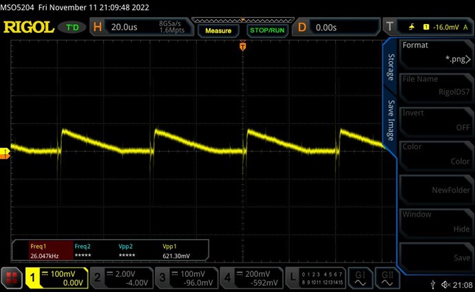
So far I always had a clean Sawtooth Waveform (SW) and assumed that all was well. But persistently L3 has not been making any difference to reducing input current, although it played a significant role in make the SW linear. Increasing or reducing L3 turns by just 3 or 6 made a huge impact on SW, so it was definitely strong enough.

The complete block in progress has forced a review from scratch. I went through many checks of which I offer a summary here.

Rechecking currents using the right-hand rule reveals that diode D3 is connected in the wrong direction, and so POC fields do not oppose. But connecting D3 correctly kills the SW. At a very early stage when I had checked this, I assumed the CCW somehow reverses the field. That was wrong.

So how was I getting such a clean SW with wrong diode polarity and without coil opposition?

The answer is in Chris' post here: https://www.aboveunity.com/thread/the-sawtooth-waveform/?order=all#comment-25542b1e-aabc-453c-8083-ac8d001b8b05 where he compares the POC SW with the Flyback Converter SW.

Due to the wrong polarity of the D3, I just had built a very efficient Flyback Converter instead of a POC!

I'm documenting this in detail so as to warn others of making the same mistake. Getting a good SW is not enough! Ensure the correct polarity of your magnetic fields first, then aim for SW.

My sincere apologies to all for this serious lapse! And thank you Chris for your patience. I assure you, that I will more than make up for this mistake in subsequent work.

All that has been documented so far in this thread is now of limited value and perhaps partly wrong since there was no opposition in the coils. I thought of starting a new thread with fresh data. But in retrospect, I feel that the documentation of steps and learning experiences are all valid, including the consequences of such a basic mistake. And the thought process of exploration and validation will stand in spite of all else.

So I will continue on this thread with the necessary corrections that follow.


Diagnostic Mode

Getting L3 to oppose L2 is simple -- just turn diode D3. But this kills the SW and makes it flat. How to get back the SW, and then how to get it to support L1?

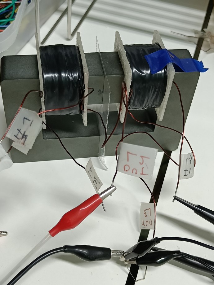
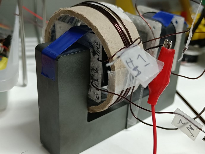
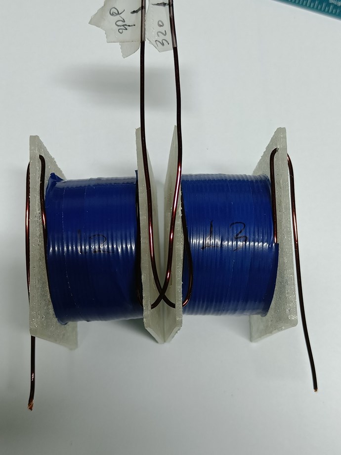
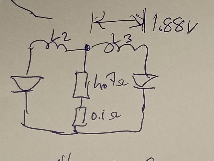
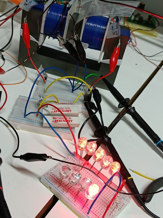
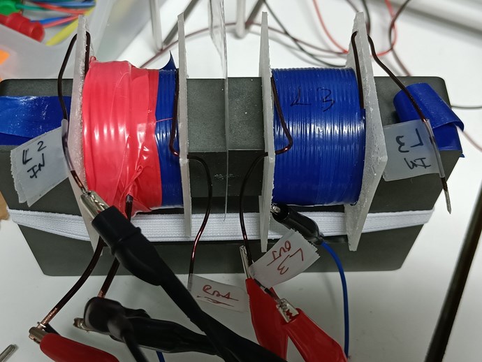
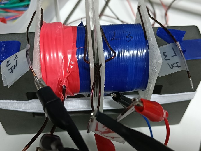
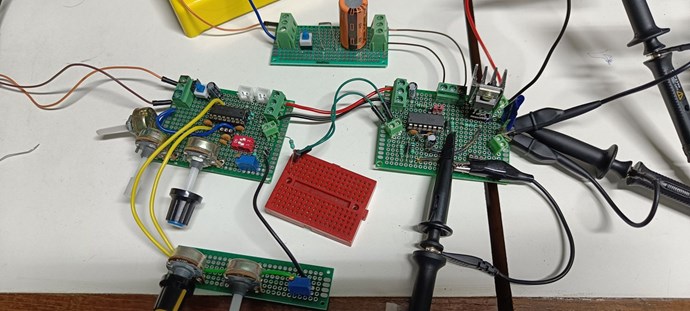
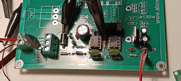
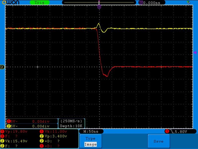
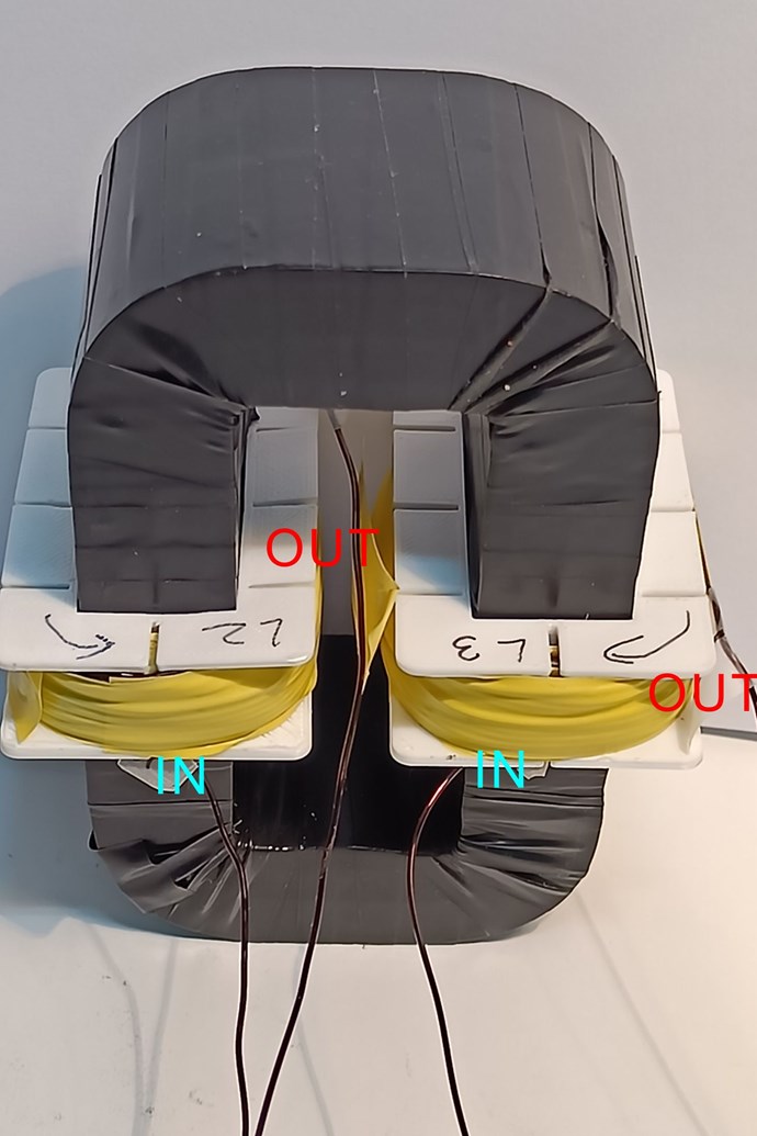
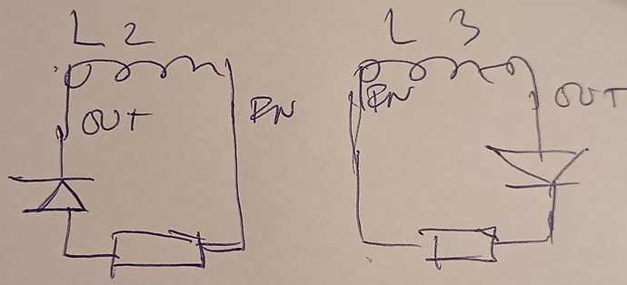
I placed the existing coils on the following circuit using a breadboard:


In this mode it is easy to isolate the effect of L3 on input current.

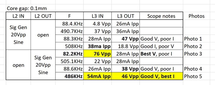
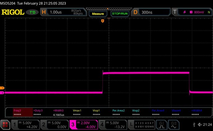
For purpose of consistency of measurements, I took an arbitrary pulse of F=1KHz, D=3%, V=6V and used about 1Ω 5W resistor as load. Also removed the 1000uF on L1 side so that the mechanical Ammeter on L1 is unbiased.

Unlike in the image above, I will refer to the POC components and measurements by the number of their corresponding coils. So D2, D3, I2, I3, V2, V3, etc. to maintain consistency across the thread.

Basic scope shots

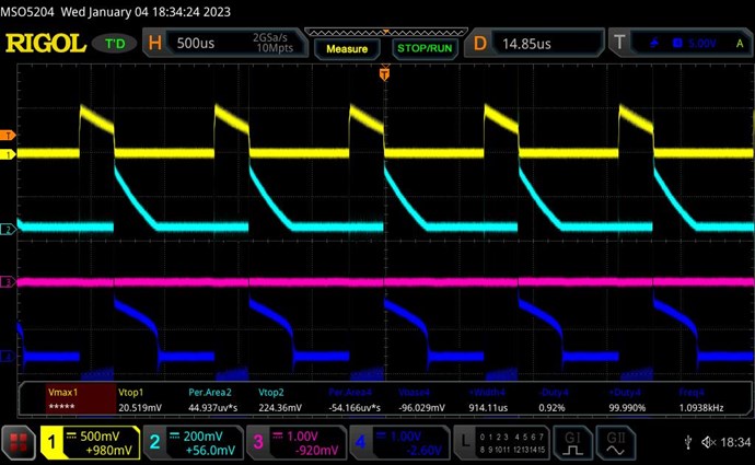
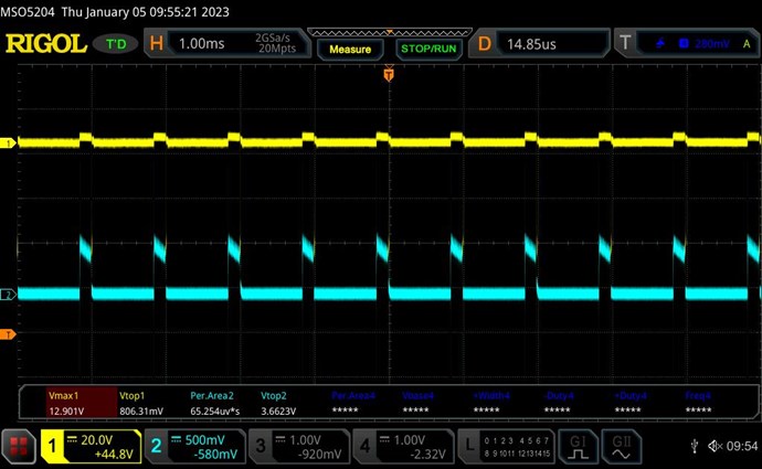
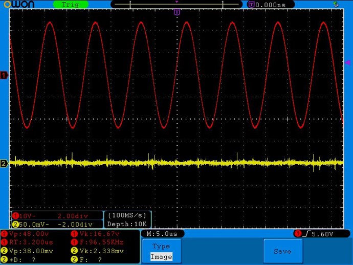
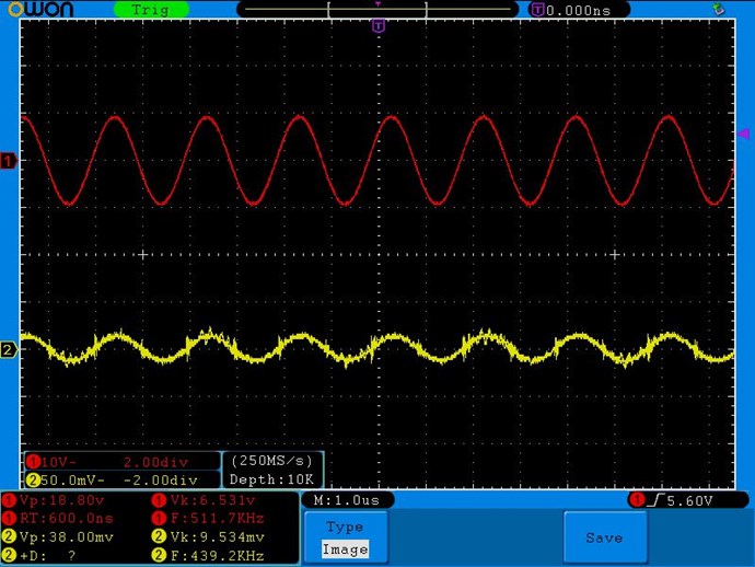
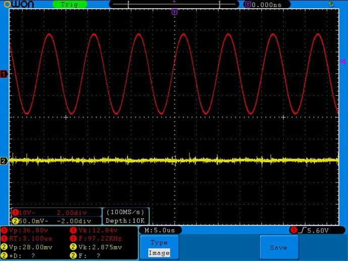
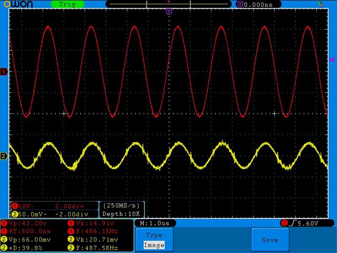
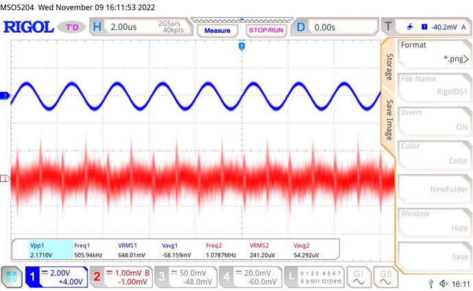
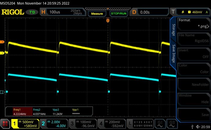
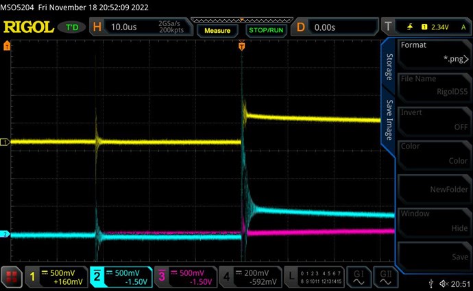
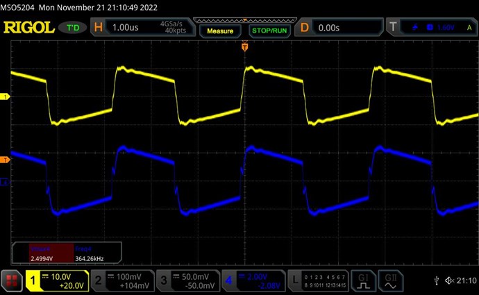
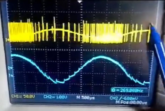
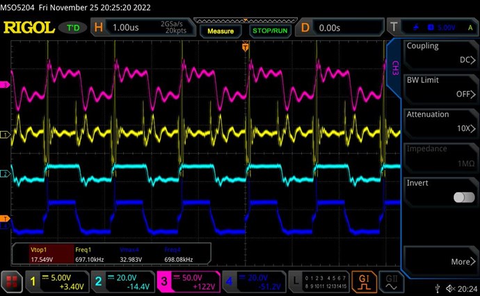
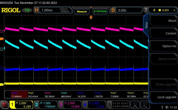
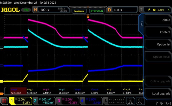
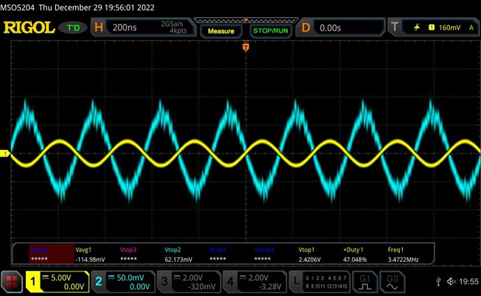
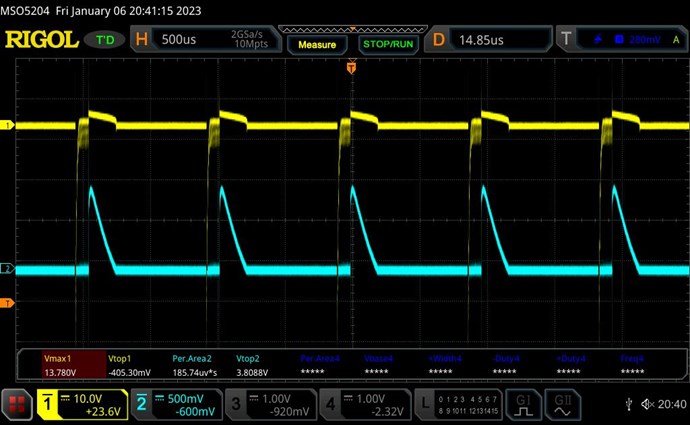
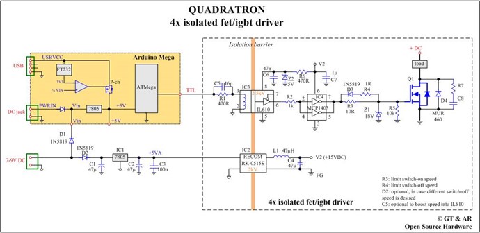
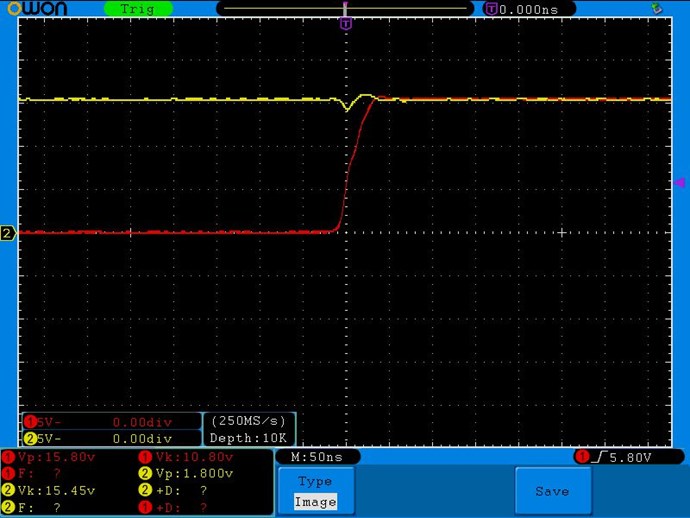
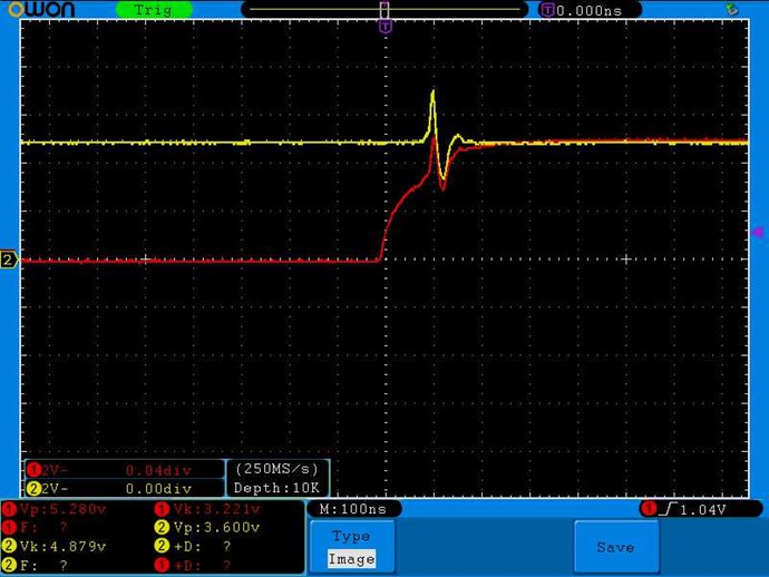
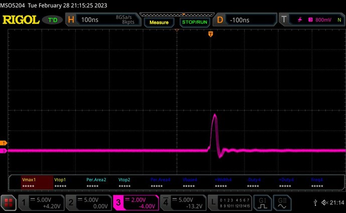
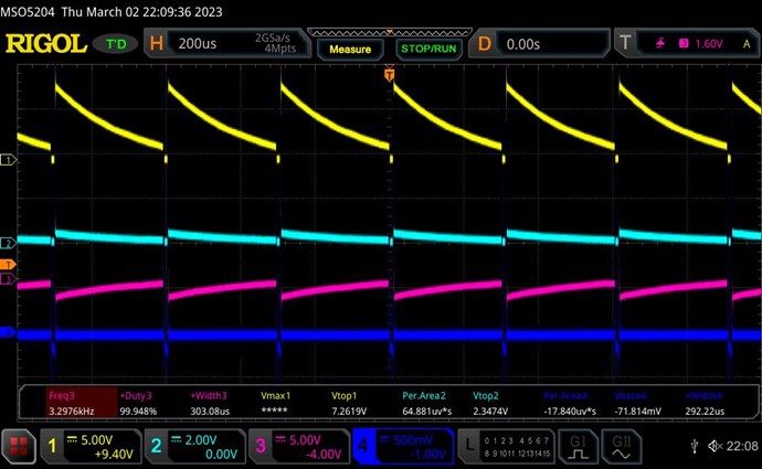
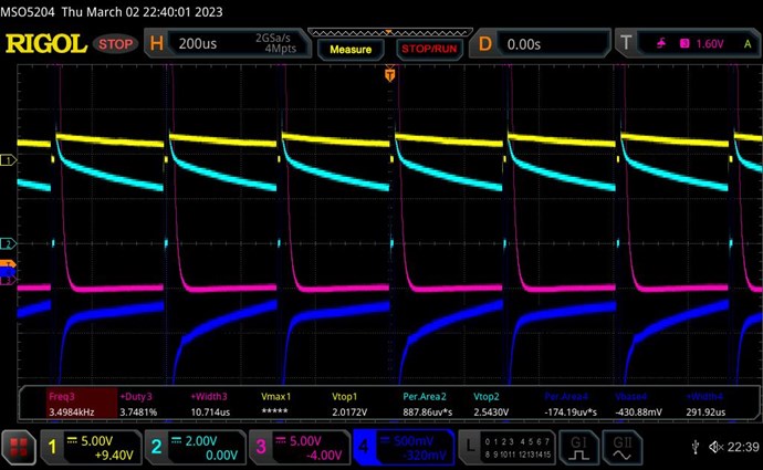
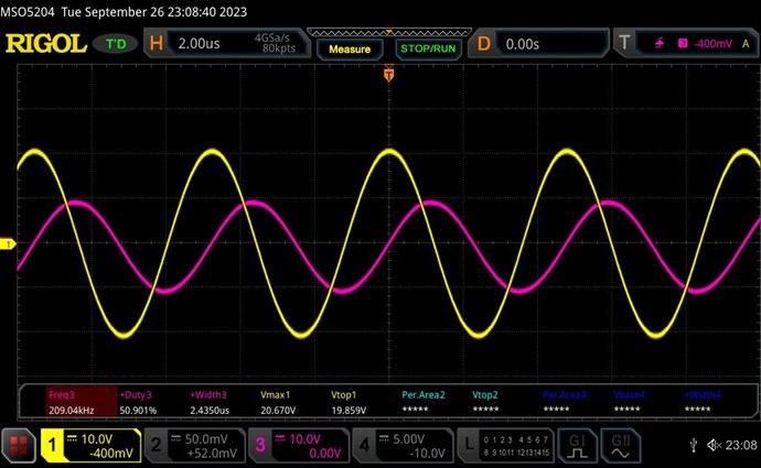
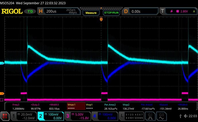
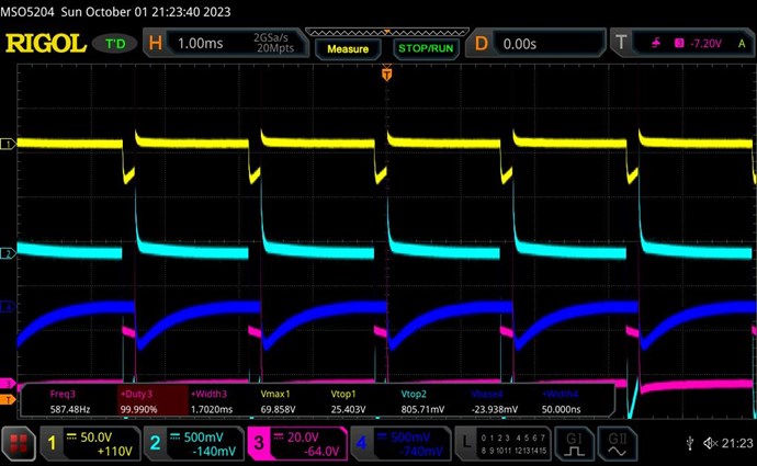
Below are the currents (Yellow=I3, Teal=I2) and voltages (Pink=V3, Blue=V2) on L2 and L3, which I origianally did with the wrong direction of diode D3:


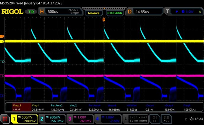
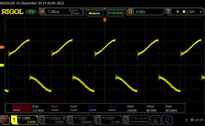
Below are currents (Yellow=I3, Teal=I2) with input pulse (Pink=V1, Blue=I1):


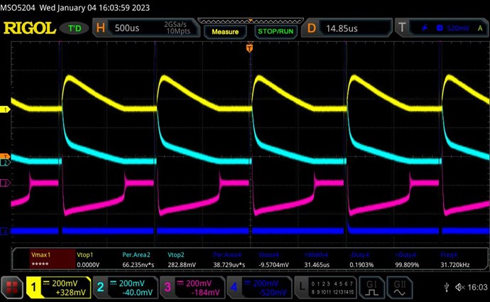
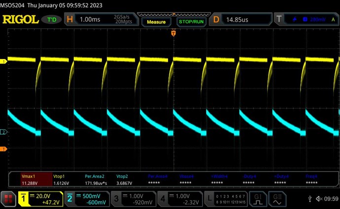
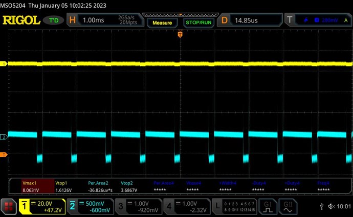
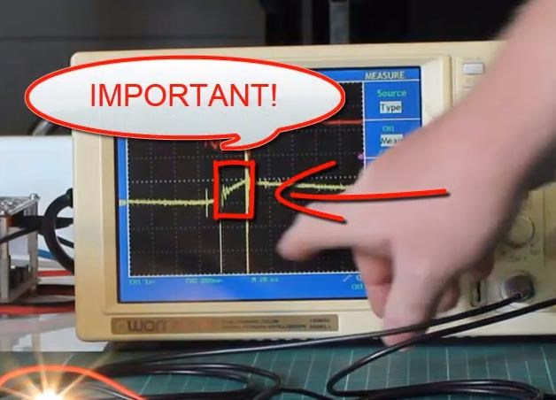
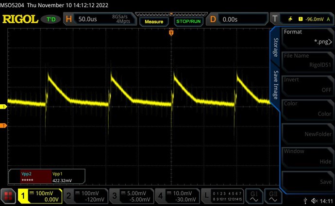
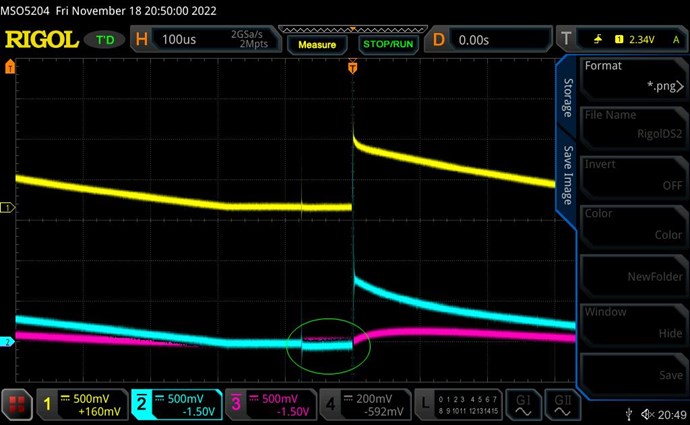
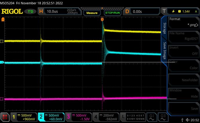
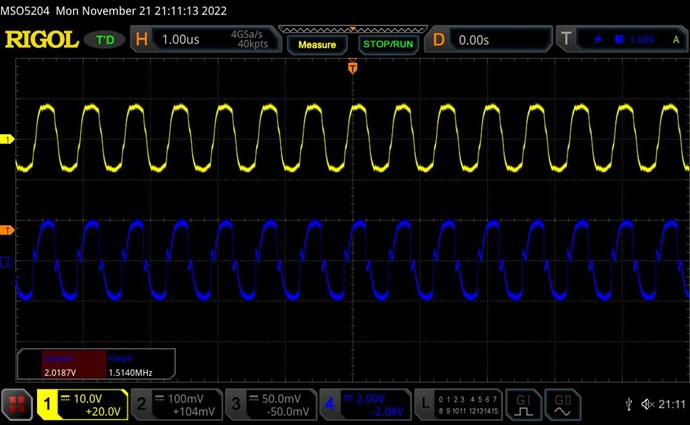
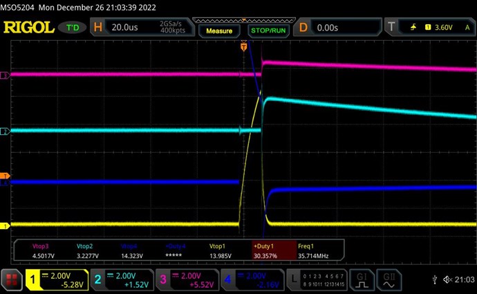
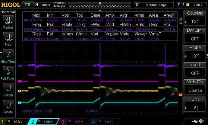
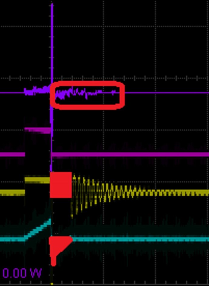
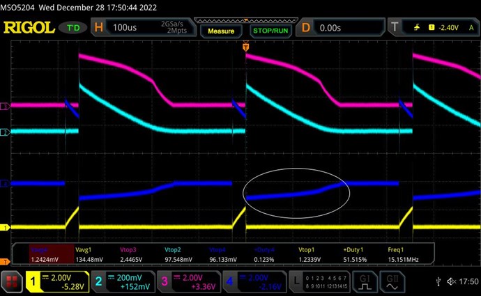
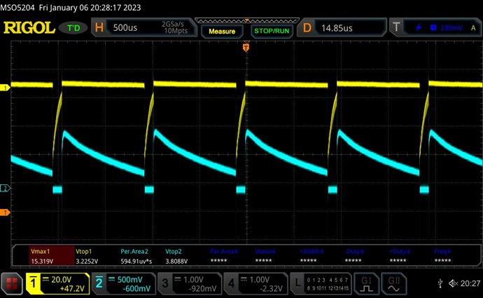
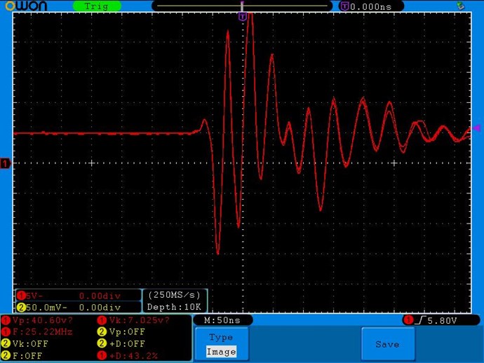
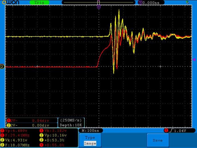
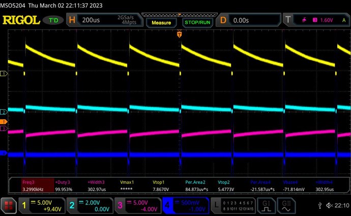
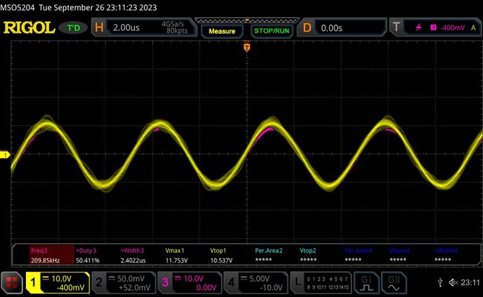
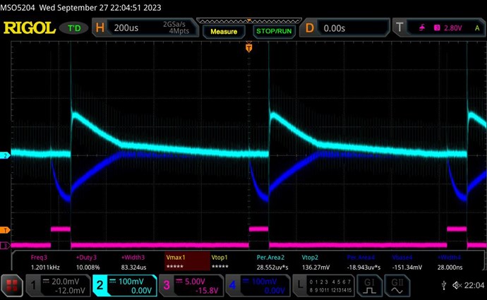
With diode D3 correctly directed we get:


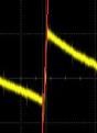
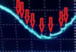
The little notch on the Teal line is actually a straight line!  I totally missed seeing this the first time while trying out all combinations (before I realised my error).

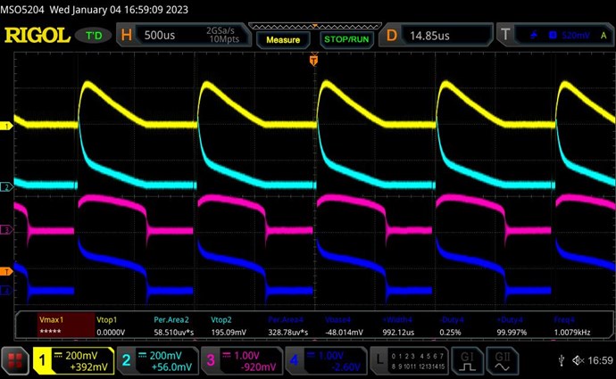
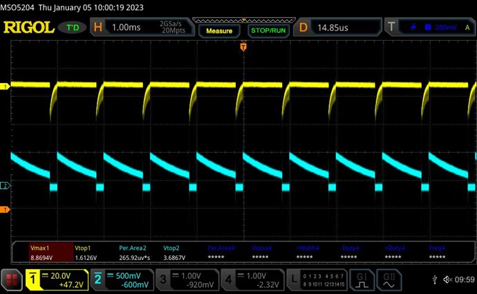
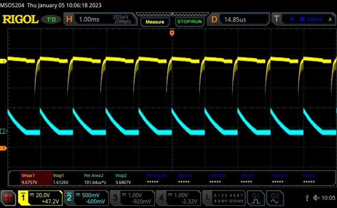
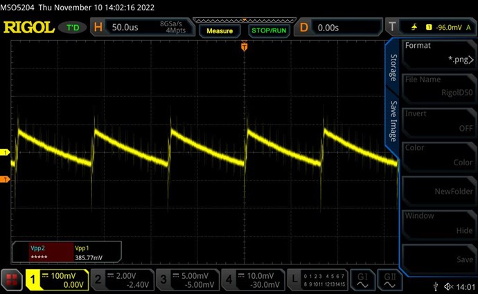
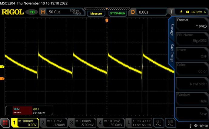
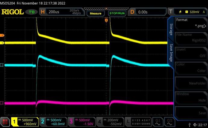
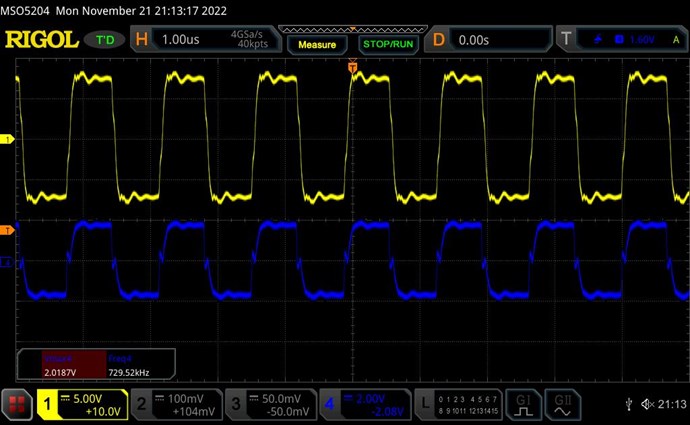
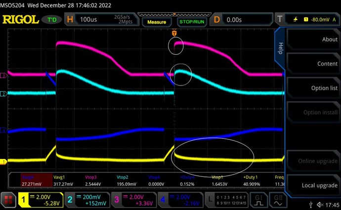
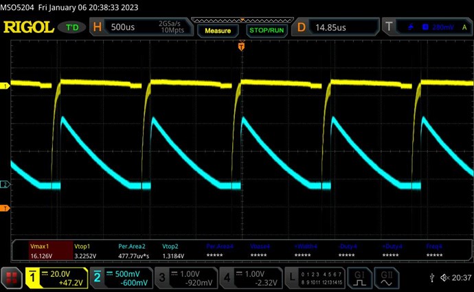
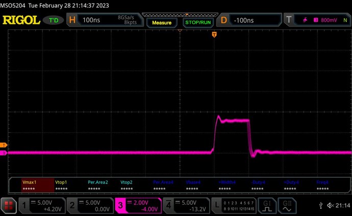
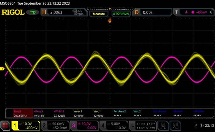
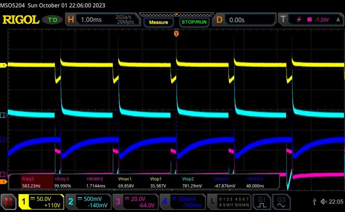
Input coil current is I1=80mA for D=3%. Raising the Duty Cycle to D=25% makes input current shoot up dramatically to I1=700mA, but the SW is clearer:


Now to check if input current L1 is supported by L3.

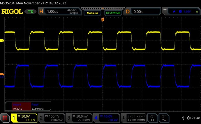
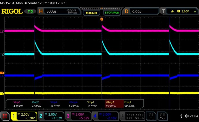
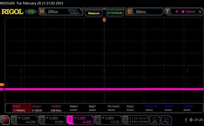
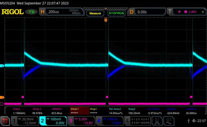
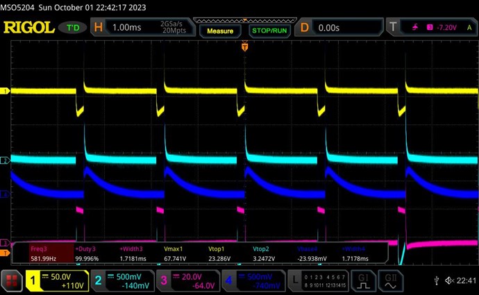
Removing L3 makes the L2 current rise and more like a SW, but the input current drops to I1=650mA:


(Just to compare, with D3 wrong giving the Flyback Converter SW there is no change in input current with L3 removed or even with L2 removed.)

But with the correct diode direction and POC SW, the input current still drops when L3 is removed, instead of rising.

This means that although we have the POC magnetic bucking, the L3 coil is not yet supporting L1 coil.

I tried every possible combination of input/out and diode positions but could not get L3 to support L1 as we want it to, or as shown by Wistiti. So next I turned to the Wistiti's configuration.


Wistiti's Configuration

In his post and video at https://www.aboveunity.com/thread/some-coils-buck-and-some-coils-dont/?order=all#comment-92df39b3-7baa-4b4b-9d37-a88c00147dde, Wisititi offers this as circuit diagram:


Wistiti wires his L1 equally across both L2 and L3. So first I tried this, and immediately got the effect of L1 current reduction with L3 on. But L1 wrapped only on L2 for POC gave even better results which are documented here.

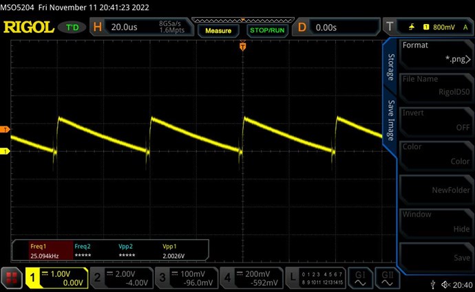
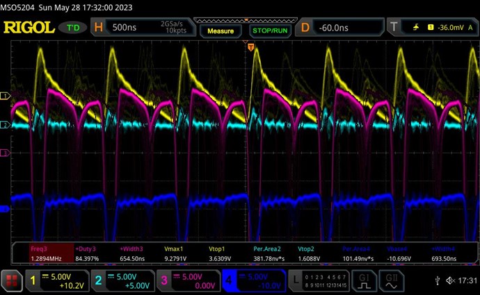
In the subsequent scope shots Yellow=Voltage and Teal=Current from coils output, and D3 is the diode at the centre of POC, and D2 is the diode at the extremes of POC.

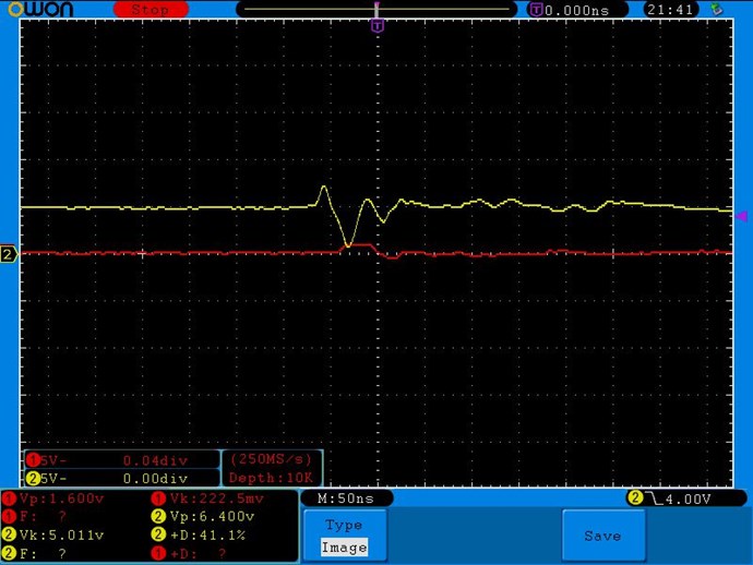
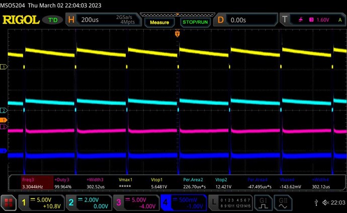
With correct positioning of both diodes the input current I1=320mA:


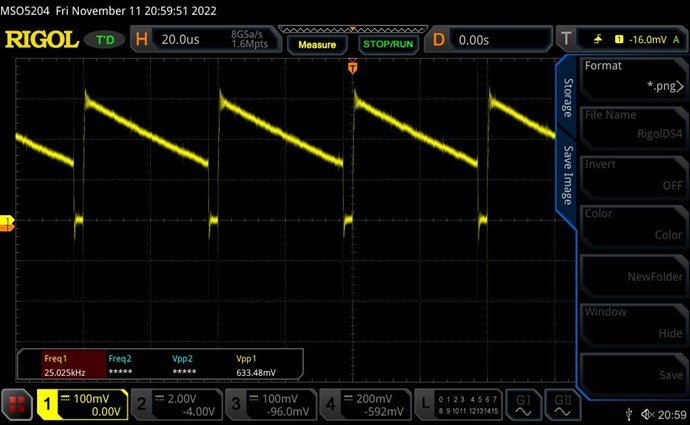
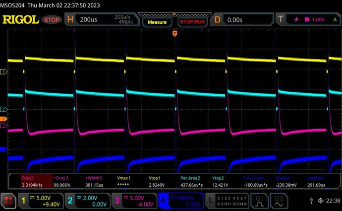
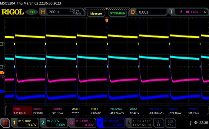
Shorting (removing) D3 correctly raises input current to I1=380mA:


Shorting (removing) D2 also correctly raises input current to I1=380mA with similar waveform as above.

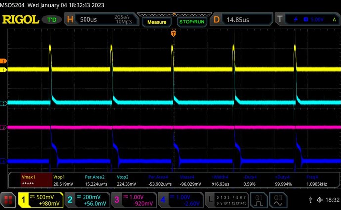
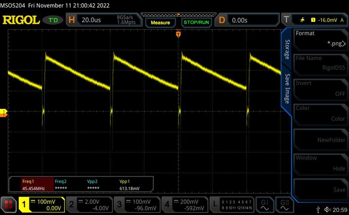
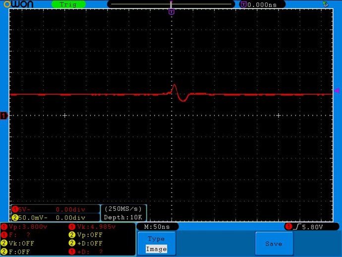
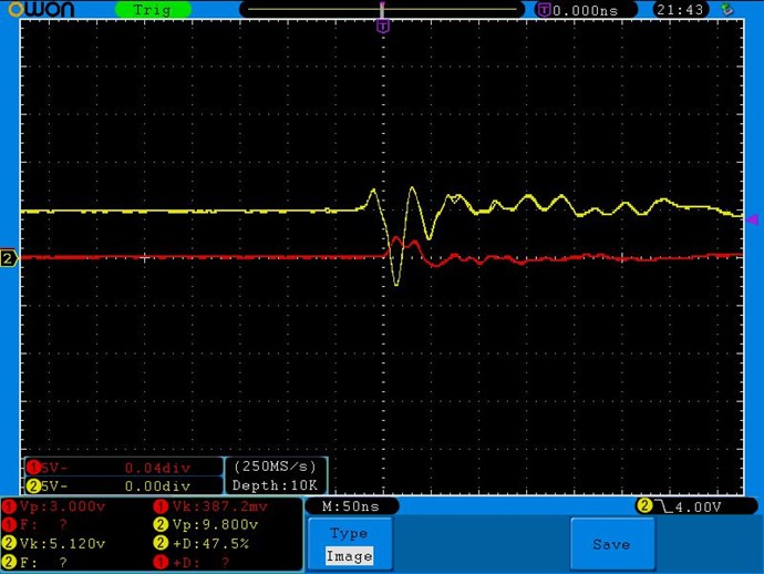
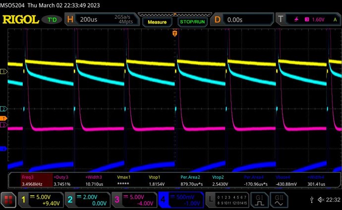
Shorting (removing) both diodes kills the SW and raises current the highest to I1=470mA:


It is obvious that the POC did not get a chance to build up to opposition, and there is no current pumping effect.

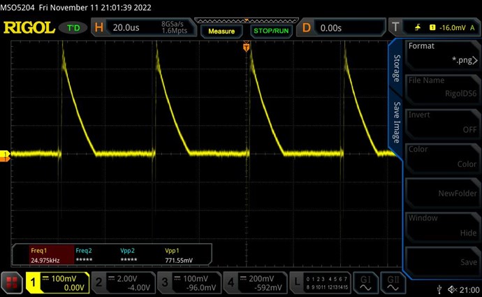
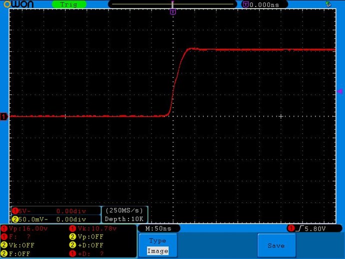
Reversing both diodes raises input current to I1=440mA and without SW:

With reversed diodes, shorting one or both of the reversed diodes raises the current slightly more with I1=460mA with similar waveform.

Here I have successfully and entirely replicated Wistiti's experiment.


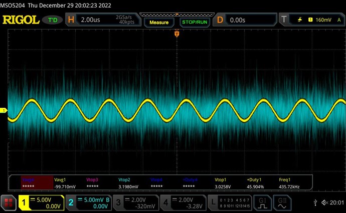
Straighening the curve

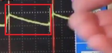
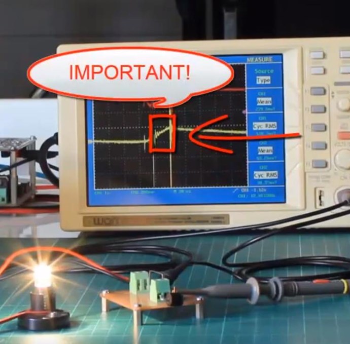
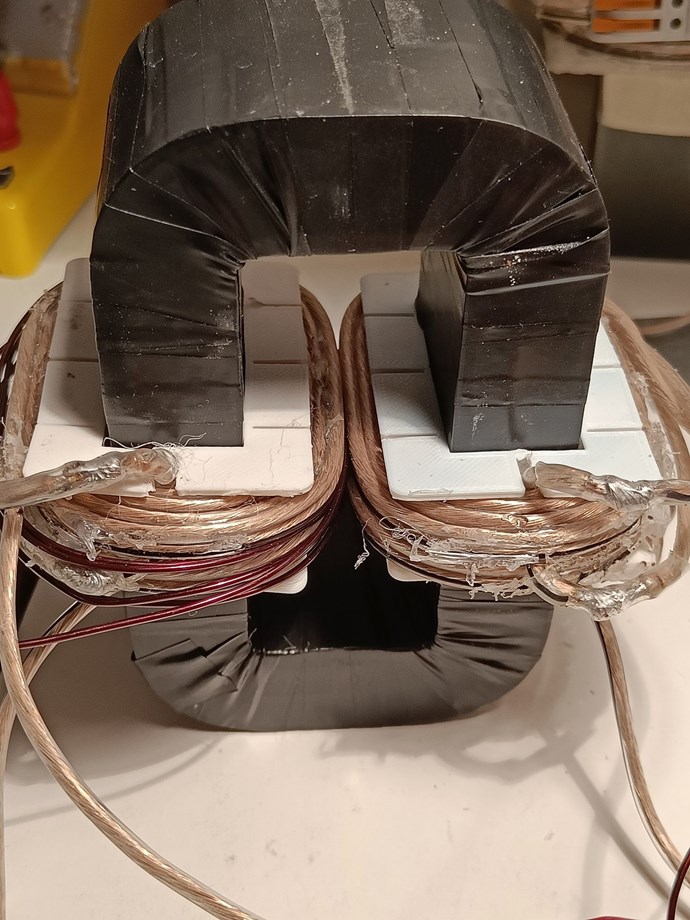
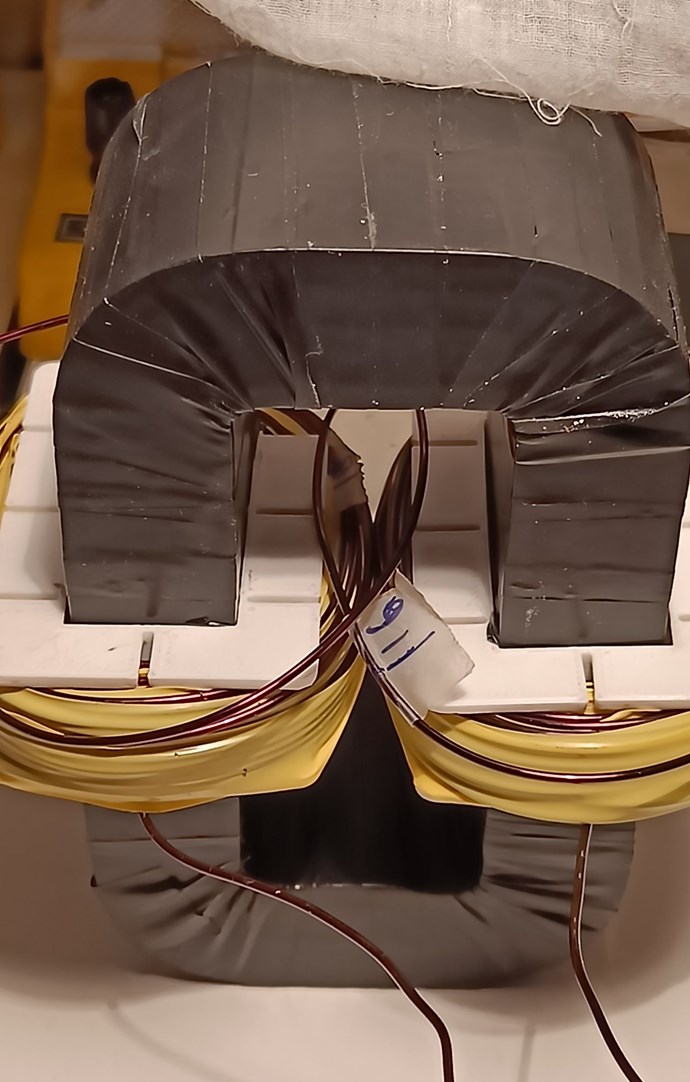
There remains one slight glitch. The SW is not yet a pure straight line. I realised that during the rearragement of coils, I had dropped the very thin piece of plastic from the gap between the cores. Re-inserting it gave the perfect SW:


Some Thoughts

This result is deeply satifying. We have a clear and significant reduction in input current with full POC function.

The load configuration of Wistiti is very new to me, and I don't recall having seen it anywhere on this website.

What is very unusual is that shorting out any one of the diodes kills the effect of L3 supporting L1. In our normal way of thinking, a single diode on one side of the load would be the same as having both diodes on both sides of the load, especially since the load is a totally passive resistor. This is very strange and needs deeper thought.

The slight gap of core made a huge difference to the SW linearity. This will now be my reference for optimum core gap -- linearity of SW! The plastic piece is 0.065mm measured by micrometer. Putting a 1mm piece made the SW very narrow and slightly distorted.

This configuration is still too new, and I will have to explore is further to get a "feel" of how the coils behave in this. But what I find promising is that the peak voltage on SW is already 3.6 volts for an input pulse of 6V. This means scaling up will be much easier and the input drop much more rapid.

At this point I have succesfully corrected a major mistake that had taken me off track, and now feel confident of further progress.

I'm actually surprised at the ease with which I was able to get all the effects once back on track, and can better appreciate Chris' frustration when people don't get it. I hope that my detailed documentation here will make it easier for many more to replicate as well as avoid the most common pitfalls.

This is very exciting and promising, and I look forward to playing with this configuration and reporting progress soon.

donovan posted this 05 January 2023

Hi,

I am just reading your last post.....I believe this is where I am at.......I appreciate that you have posted in so much detail......tonights efforts will involve studying your work while I troubleshoot mine.

Thanks,

Donovan

Chris posted this 05 January 2023

Hello ISLab,

This is by far your best post and set of experiments! Thank You for your very professional Approach!

NOTE: POC Function is broad and more than one configuration exists to achieve the same Effects! Input Current going Down Under Load is the critical aspect of all Free Energy Machines! Floyd Sweet used 33 Micro Amps under loaded conditions!

I agree:

But in retrospect, I feel that the documentation of steps and learning experiences are all valid


I agree, this is a Learning Curve and we must always force our brains to NOT assume, because that's the main issue with all of Science Today!

Yes, there are several Polarities that need to be taken into consideration, which your experiment shows! The Correct Polarity must be obtained, which once done, becomes easy! Everyone must follow the Big Red Arrows for conformity!

You are right, we must think about this the right way, to make this work, it is VERY Easy, but not as intuitive as many think, again the assumptions many make, hold them back from a whole new, hope filled future!

I believe you will now understand better why I have said:

Knowing that your Input Coil Does Not Generate your Output Voltage!


I am very pleased you have achieved these goals and now all you have to do is some deep study and documentation, and look at getting the Magnetic Fields up so as to bring the Output Power up, of course one follows the other as we all know!

Well Done ISLab! I am impressed with your effort! You have achieved Asymmetrical Electromagnetic Induction, a feat that 99.99999% of all Researchers don't even know exists!

Don't give up, because you're on the verge of big breakthroughs, breakthroughs others here have also gained and achieved! Breakthroughs the Other Forums will never achieve, because We are Light Years Ahead of the other Forums!

If only more would join in and learn, we could free Humanity tomorrow from the Chains of Ignorance!

Best Wishes,

   Chris

ISLab posted this 06 January 2023

CIrcuit updates

I soldered a UF4007 diode on the MOSFET as suggested by many here and added a finer control on Duty Cycle for future tests.


Exploring the Coils

Activating the circuit which was exactly the same as the last time, gave the SW as before. Then shorting D3 to check for rise in input current gave no change!

I tried again, checking every connection. All was ok but I got no change, or a barely visible 3mA or so increase.

I disconnected one side of one coil, then both sides of either coil, and the SW remained unchanged and the input current I1 stayed unchanged!

Disconnecting all coils broke the SW but left I1 exactly the same.

Finally, removing the thin plastic from the gap got back the effect and I1 rose by 20mA. The difference was caused purely by the now increased magnetism that clicked together the cores and held them quite tightly. The thin gap was enough to break this magnetism.

The difference between yesterday and today was a slight drop either in pulse voltage V or in Duty Cycle D, just enough to bring the coil magnetism below the threshold required for current reduction effect.

Looking back I was lucky to try with 6V last time, as that is the minimum required for my coils. Today's failure was due to a very slight reduction just on the edge of the effect.

Slightly raising V a little got back the effect suddenly and I could put back the thin gap to make the SW linear again. The effect also returned with a large increase in D.

The difference between non-interacting coils and magnetically interacting coils is heard by a sudden increase in the singing volume (I still have F=1KHz).

In fact there was a sudden increase twice from 6V to 7V pulse, each giving better interaction seen in an increased drop in I1.

All this shows that a minimum level of magnetic interaction is required before current reduction is suddenly seen. This is best done by raising voltages rather than by raising D, as seen below. You will know this effect has kicked in when your cores will attract and click together, making it difficult to separate them by finger pressure.


Preliminary Measurements

For convenience I will refer to the change in input current I1 with D3 shorted as ΔI (Delta I) hereafter.

Some observations:

  • raising D raises I1, but also raises ΔI almost proportionally.
  • raising pulse V raises I1 almost proportionally, but raises ΔI much more than proportionally. This is key to OU.

For example:

  • For V=7V, with D=5%, I1=60mA which increases with D3 shorted I1=70mA, giving a ΔI=10mA. A gain of about 14%.
  •         with same V,  with D=10%, I1=180mA which increases on short to I1=220mA, giving a ΔI=40mA. A gain of about 18%.
  • For V=14V, with D=5%, I1=115mA which increases on short to I1=180mA, giving a ΔI=65mA. A gain of about 36%.
  •        with same V,  with D=10%, I1=460mA which increases on short to I1=510mA, giving a ΔI=50mA. A gain of about 10%.

These figures are approximate as everything is still on breadboard and the shorting is done by touching wires by hand. With the last settings the D2 and D3 diodes got very hot.

At one point, a much lower D and higher V, I got a distinct gain of about 50%, when input currents were low in the range of 30mA. I did not record the output power in any of these, since this is only a preliminary exploration to get a feel of how the coils behave in this circuit.

With the last setting of V=14V and D=10% the following are scope shots for various core gaps.

No core gap gives:


Core gap of thin plastic of 0.065mm gives:


Core gap of 1mm gives:


The peak current in the first and second images are over 1A for a nearly steady generated voltage of 3.2V. This is without optimising the load or input F and D. Shows promise.

donovan posted this 07 January 2023

Hi,

I am new here......where did you place the UF4007, on the MOSFET?

Donovan

ISLab posted this 08 January 2023

where did you place the UF4007, on the MOSFET?

Between Source and Drain. See the section called Avalanche Protection here: https://www.homemade-circuits.com/mosfet-protection-basics-explained-is/

It is not necessary for the effect, nor even essential for protection unless you are handling high voltages and currents on the Input, AFAIK. Must be ultra-fast though for our purpose.

ISLab posted this 03 February 2023

Although I made some interesting observations with the Wistiti circuit, I've held back posting as I wanted to improve my setup first. (I will report on those later.)

My progress has been blocked, I believe, because my TL494 based frequency generator does not have sufficient precision on duty cycle, and my high-side IRF 2110 MOSFET driver circuit is getting very quickly hot when I raised pulse voltages beyond 12V as the high voltage is leaking back into the driver output due to issues with the high-side bootstrap circuit, etc.

So I decided to build the https://www.aboveunity.com/thread/reliable-and-flexible-switching-system/ to at least be able to push higher voltages without hassle.

I've soldered one channel on the board to test:


Voltages are ok at a stable 15.3V within the circuit for an input voltage of 7.0V or above. MOSFET is switching fine. So everything seems to be ok.

Except the pulses are badly varying in frequency as seen here:


My original input pulses are rock steady and clean. They enter the IL610 at about 3.6Vpp. But the output from the IL610 is coming like this with the shaky pulses as if the frequency is varying all the time around the actual F.

The above photo shows the placement of probes measuring just at the output of IL610.

@Chris, and others, could you please indicate what could be the problem and how I might try to fix it?

Plasmonic posted this 03 February 2023

Hey ISLab,

My first thought was some kind of supply ripple causing a reference trigger voltage to change but looking at the IL610 I'm not sure that is plausible.  I'm still curious though what the voltage looks like across pin 8 and 5 of the IL610 if anything is showing up there.

Nice PCB by the way, I have been trying to get some made through JLCPCB but when I upload the files I get a digital equivalent of a blank stare in return.  Lets see if I can get it to work today.

Matt

  • Liked by
  • Chris
  • ISLab
Chris posted this 03 February 2023

Hi ISLab,

I think Mat is on the right track.

Is this spurious effect only at the Mosfet? Or can you trace this back further? If so, how far back? What Component?

Best Wishes,

   Chris

ISLab posted this 04 February 2023

Hi Plasmonic and Chris, thank you for the tip!

Checking the voltage across IL610 pins 8 and 5, there is a short but large bump:


The bump happens exactly for the duration of the rising edge of the pulse:


It could also be on the falling edge. I did not check both at the same time.

The above is just with the signal in and no output fed through the MOSFET. When I feed about 7V on the MOSFET into a coil, this bump goes wild:


Removing the pulse input to CN2 removes the bump completely.

No change in the bump by adding an extra 100nF on Pin 8.

Any suggestions?

Chris posted this 04 February 2023

Hey ISLab,

Hmm, bad IC?

Without having more info, it appears there is a Power Dip on the IC ( IL610 ) that may be causing this instability. Check the Cap, C4, for the same dip:

If we have a stable DC Supply at 15 volts, if we do, then its not power.

If we don't, and you see the same dip, its possible the RK-0515S is struggling to keep up with the Isolated Supply Power to the circuit.

I believe there are a few models, each rated at different wattage output. Get the highest rated.

Any components getting hot?

Best Wishes,

   Chris

  • Liked by
  • Augenblick
  • Plasmonic
ISLab posted this 04 February 2023

I have the RK-0515S/H6 which has output rated for 66mA and 1W. This does get slightly warm after being in use for 10 minutes when the MOSFET is driven, but not warm at all when it is not driven.

I recall the power dip was on the entire 15V line, but will check this again carefully. Will also try replacing this and check.

  • Liked by
  • Plasmonic
  • Chris
donovan posted this 04 February 2023

Hi,

The one waveform is interesting, showing a overshoot, followed by an undershoot, on the supply line, as the output waveform is rising (taking power).  I wonder if we are reaching the transient response time of DC-DC converter. A fast, large load and the converter overshoots, trying to keep up.

On my experiments, one thing I did last week was clean up the wiring for the power circuit that drives my L1.  I used heavier, shorter wires, and added some bypass capacitors close to the MOSFET.  Right beside my MOSFET/L1 I used a 15000 uf, 1uf, and .1uf in parallel.  The use of bypass capacitors in modern electronics seems to have fallen by the wayside.  In high power, fast circuits bypass really help.  And using 2/3 in parallel makes sure at least one of them is effective at the required frequency at any instant.  In my circuit, the extra bypass capacitors cleaned up the waveforms, and made it easier to see the magnetic resonance.

My two cents worth.

ISLab posted this 04 February 2023

Some more checks on the 15V line placing the pulse (red)  next to the 15V line (yellow).

On the rising edge of the pulse:


On the falling edge of the pulse, again another dip, where 15V line is measured after L1 inductor:


The same measured before L1 inductor directly on the 15V output:


L1  does have a very slight effect to reduce the bump.

Note that the both ICs are inverting. So each may be drawing when it switches ON. Hence the difference between the rising and fallin edges. Perhaps?

The RK-0515S/H6 gets warm within a few seconds when there is load on the MOSFET (perhaps because the driver draws more current). Otherwise it is cool. The 7805 is always cool.

The RK-0515S/H6 is clearly overloaded. I will try with a different piece of RK-0515S/H6 next, and perhaps with several caps as suggested by Donovan.


Q1) @All, one difference in my circuit is that the MOSFET is IRF840. Could just this MOSFET be drawing too much current?

Q2) @Donovan, do you suggest I put caps of 1uF and 0.1uF on the 15V output in addition to the 470uF?

Chris posted this 04 February 2023

Hey ISLab,

A bigger cap at C4 may be helpful? I don't think the Ripple, is enough to create this issue, its not sufficient to Brown out the IC in my opinion.

Re-Check your Decoupling Caps at: C6 and C7, make sure they are Ceramic, 100nf caps.


Any issues with signal before the IL610?

EDIT:

Q1) @All, one difference in my circuit is that the MOSFET is IRF840. Could just this MOSFET be drawing too much current?


Yes! But you said you disconnected the Mosfet, did you not?

The above is just with the signal in and no output fed through the MOSFET.


Best Wishes,

   Chris

donovan posted this 05 February 2023

Hi,

Nice scope shots, showing both waveforms.

I would try a 1uf or a 10 uf, in parallel with C6, and see if it has any effect on the waveforms.  I would also try a 1uf or 10 uf in front of L1, after the RK0515.

These are the fun ones to troubleshoot!

Donovan

Chris posted this 05 February 2023

Hey ISLab,

What wattage is your inductor:


Getting bigger 1/2 watt, or a bit more, Inductor may be worth while:


Worth looking into!

This, I do not believe is causing the issue, but may help you in finding the issue!

Best Wishes,

   Chris

ISLab posted this 05 February 2023

Hi Chris and Donovan, thank you for your inputs!

But you said you disconnected the Mosfet, did you not?

I disconnected the pulse power supply to the MOSFET but did not remove it from the circuit.


So now I removed then MOSFET, then IC2. But the frequency wobble did not go away.

Next I soldered the minimum of parts on Channel 3, just to activate IC1 and the power using all new components. Measured each component value to double check.

Same wobble in Channel 3.

Put 0.1, 1, 10, 100, 330uF in parallel with C6. No change.

Put 100nF in parallel with C2. No change.

My input pulse comes from 11V ouput of TL464 through 1K resistor to R1. Voltage drop on R1 is from 4.2V to 0.7V, meaning 7.5mA on IC1 input. I tried to reduce the 1K resistor to raise current on the input up to 11mA. I thought it made a very slight reduction in frequency wobble, but barely. But I did not want to risk higher current as recommended input current is 5mA.

Then finally I put a 20pF in parallel with C1, and the wobble stopped!

The existing C1 is suppod to be 15pF, but shows 20pF on LCR meter, as also the new one added in parallel, giving a total of 40pF.


I have yet to test on Channel 1 with larger C1. It it late now so will try tomorrow.

Just to show you the actual capacitor used, I have placed it beside 100nF. The 100nF is Polyester Film rated for 100V. The 15pF is ceramic, but I don't know its rating or how to find it.


My testing F = 1KHz. I don't know what exactly C1 does or how its value influences the pulse. Any inputs will be much valued on how this works and what to do next, and what value to finally use. Thank you all for your help!


@Plasmonic: .... JLCPCB but when I upload the files I get a digital equivalent of a blank stare in return

I figured out the problem and corrected it before I could make my PCBs. Will post the correction shortly in the original thread: https://www.aboveunity.com/thread/reliable-and-flexible-switching-system/


Chris posted this 05 February 2023

Hey ISLab,

Then finally I put a 20pF in parallel with C1, and the wobble stopped!


You need to use Ceramics for Decoupling Caps:

Re-Check your Decoupling Caps at: C6 and C7, make sure they are Ceramic, 100nf caps.


Pleased you got it sorted!

Best Wishes,

   Chris

ISLab posted this 06 February 2023

The story got even more strange.

Replacing Polyester Film on C2 with ceramic capacitor made no difference to the wobble or the voltage dip.

Looking for an optimum C1, I found that sometimes adding another 15pF in parallel worked fine but sometimes not. Then I found that the wobble stops when my hand touches the input signal and my foot is touching the floor and earthing the line.

The wobble stopped even if I touched the signal as it comes out of the TL464!

So I replaced the PSU on the TL464. No change. Connecting the scope probes to the TL464 was earthing the line and blocking the wobble. Removing the scope from the TL464 kept the wobble in the MOSFET output.

Touching the TL464 pins 1, 2, 4, 5 (all related to pulse timing) by hand makes the wobble dramatically worse. So I suspect the problem is some kind of parasitic capacitance in the TL464 output that was oscillating with the coil in the input of the IL610. Because so far I had no problem with the TL464 output. (Or perhaps the fact that I was monitoring its output on the scope was grounding the line and so suppressing the wobble.)

Finally I replaced the TL464 with a professional Signal Generator, and the wobble was gone!

But the voltage dip still remains. On the 5V line measured on Pin 9 of IC1, it is quite big -- nearly 3.6Vpp:

where Yellow is the 6V line and Red is the IC1 output on Pin 6.


Powering the MOSFET gives strong ripples on both:

but F on the MOSFET stays steady.


The Reliable and Flexible Switching System has stood its ground well, so I will leave the circuit as in the version 3 by Chris, and focus instead on building a "reliable and flexible pulsing system" to match it.


Looking back, I'm wondering how much this may have affected my experiments and results. It seems to me that if the F was wobbling a lot, I would definitely have noticed. I was alwayd monitoring the TL464 output to watch the F and D values and so the lines were grounded by the scope, preventing any wobble. But it does suggest that the stability of the TL464 circuit (or at least my board layout) had high parasitic and other influences which may have affected the precision of F and D values. I had noticed drift in F which I assumed was from temperature rising in components. But now I suspect it was from this.

My apologies to all for the trouble and false alarm. I hope my learning experiences will save similar troubles to many others.

Chris posted this 06 February 2023

Hi ISLab,

Fact: I don't have the issues you do!

Maybe the difference between cheap Chinese IC's and the originals!

Best Wishes,

   Chris

ISLab posted this 09 February 2023

[Please note that my problems described with the Reliable and Flexible Switching System (RFSS) is in no way related to the RFSS design which is robust and well-tested by Chris. It is entirely specific to my implementation. I'm sharing my problems here in detail seeking help and guidance from all, and in the hope that others who face similar issues may be helped by whatever solutions are found.]


The voltage dip on the RFSS internal power is timed with the drop in the pulse when the coil throws a sharp Back-EMP which overlays a noise pulse. This ripples into my entire DC power line outside the RFSS and into the pulse timing circuit's power line. As the voltage on the MOSFET pulse rises, this dip grows with a large noise pulse until it swamps the entire circuits power line momentarily (5V for my pulsing timing) and resets it.

After much experimentation, I finally isolated the cause of the voltage dip and found a work-around: placing a 0.1uF across the MOSFET Source and Drain removes all the noise, and leaves the original power dip only, which does not pollute or swamp the circuits outside the RFSS.

This the measurement in the RFSS at the 5V line across the 5V Zener without pulse voltage on the MOSFET:


The dip is very short -- a little over 50nS. Seen only when you zoom in. It is related to the internal RFSS circuit but does not affect anything negatively, and does not go outside the RFSS. It can be safely ignored.

When placing 2.5V across the MOSFET, this overlays with a noise pulse:


When pulse voltage is increased to 5V the noise pulse grows proportionally:


But when a 0.1uF is placed across MOSFET Source and Drain, the noise vanishes:


The power dip is slightly larger than the original, but does not grow further, and the noise pulse is gone. All the connected circuits function normally all the way up to the 14V that I've tested.

I'm happy with the work-around. But I still do not know why this is happening. Perhaps it is specific to the MOSFET IRF840 which has a rather high Rds(on) of 800mΩ (compared to the Cree Wolfspeed which can go as low as 15m&Omega, and hence to be replaced soon. Or perhaps it comes from placing the MOSFET through a connector block like this:


Either way, this is specific to my current implementation, and the work-around will have to stay for now.

But I still want to understand why this is happening and why the 0.1uF solves it, and whether that would affect anything else in the coil pulsing and the POC effect. I request anyone here who understands this to please explain, as my knowledge in linear electronics is limited.


Further steps

I'm waiting for the new AMCC core and will wind a longer coil as soon as this arrives.

Meanwhile, I've been working on a high resolution programmable pulse timing circuit based on the Arduino and the AD9850 DDS signal generator. This is already giving very precise F (down to 0.3Hz) and can comfortably go up as high as 20MHz. I'm working on some options for the D control which is currently manual from a IC555 on-shot monostable -- not yet programmable.

This would allow automatic sweep at various speeds programmatically.

I intend to share the entire circuit and the code here once it is fully developed and stable.

ISLab posted this 16 February 2023

I've received my AMCC cores, and am already struggling with the metal flakes.

Could anyone please share some guidelines on safe use of AMCC material, and any way to wrap them safely to avoid injury and rusting?

I remember seeing a post with a document of handling AMCC in one of the threads, but cannot find it now.

Thank you for your help!

Plasmonic posted this 16 February 2023

Hey ISLab,

I sprayed mine with wd-40 wiped them down and wrapped each half with a continuous wrap of electrical tape on each leg.

Matt

ISLab posted this 20 February 2023

@Plasmonic: Thank you Matt! I will do the same.

Btw, I found the document. It was posted by Jagau here. It recommends Rustlick 631 which seems to be equivalent to WD-40.


New Switching Board

My new RFSS is ready, tested and working with C3M0015065D MOSFETs:


I've inserted switches at the power lines of all four channels so that I can use only the channels needed, and avoid needlessly heating in the unused ones.

The Cree C3M0015065D MOSFET has an Rds(On) of 15mΩ (compared to IRF840 which has a Rds(On) of 800mΩ ) and is soldered directly onto the board.


Power bump and solution

At first the change in MOSFET dramatically raised the current in the L1 coil, giving currents 0.4A for barely 3.5V input pulse at 6% duty cycle. The problem of voltage dip documented earlier also was present (suppressed by the 0.1uF on the MOSFET), but now the spike overload was reached at 3.5V instead of 7V or above earlier. And the Sawtooth Waveform was no more seen.

I noticed also that if the 0.1uF ceramic capacitor touches loosely or is moved (as when held by hand) there were sparks at the point of contact!

After many hours of debugging, I found that removing the oscilloscope probes from inside the RFSS isolated portion of the circuit solved everything! Now the sawtooth waveform on the coils output was restored, the power glitch which was knocking out the pulsing circuit vanished, and the high current draw on the pulse dropped to normal.

The problem was from some ground loop created by the oscilloscope ground / probe which was allowing the sharp pulse to induce large ripples in the isolated portion of the RFSS circuit.

Now I can raise the pulse voltage to 30V without any problems or side-effects! The MOSFETs stay cool even at high voltage and current up to 1A without needing heatsink.


One Remaining anomally

I noticed early on that if I connected the live input pulse circuit to the RFSS first and then switched on the RFSS, then it would not come on, and the RK-0515S has at output of 2.5V instead of 15V. I thought it might be a bad piece, but now I find this is the case with all of the channels.

My input pulse is about 3.5V height from a 5V Arduino circuit and IC555; the RFSS runs from a separate 7V PSU. Could this be causing this? Any advice is welcome.

For now I find it necessary to switch on the RFSS first, without any signal on the input. Then all works fine.


Next steps

My Arduino + AD9850 is working well with manual and auto-sweep modes with a selection accuracy of 0.3Hz and rock solid stability.

The duty cycle is currently manual using an IC555. This must be automated now and made to be software controllable to as small as possible.

ISLab posted this 28 February 2023

Hi Friends,

I've been fully immersed these last eight days building my high precision pulsing circuit. At this point I finally have it working to my satisfaction and with the convenient features needed for POC research.


The top leff is an Arduino Vidor 400 which contains an FPGA (Field Programmable Gate Array) and which is the master controller for the entire circuit. Top right is an AD9850 DDS Signal Generator with high precision frequency ranging from below 1Hz to above 20MHz, available as square as well as sine waves.

The FPGA is "programmed" into a custom circuit that fully manages real-time data from the three Rotary Encoders (with internal debounce) and their three pushbuttons (with internal debounce), and most importantly a high precision Monostable pulser that is fully programmable and controllable from the Arduino code. The entire FPGA operates internally at 150MHz, offering very high precision and timing totally independent of the Arduino software speed. This could be further improved by replacing with a still higher frequency FPGA.

The customr circuit looks like this in its heart:


The Arduino code programs the FPGA and the AD9850 to give precise frequency (down to 0.3 Hz precision) and precise pulse width (down to about 8.5nS precision). The three Rotary encoders and their buttons are used to select the frequency F and pulse duration D. Pushing their buttons allows for selecting the speed of change of F and D to easily scroll large steps or slow down to very small steps.

There are also special modes which sweep the F up or down automatically at various speeds and steps, all of which can be manually changed while the auto-sweep is ongoing. The LCD screen shows current values of F and D, and the current mode of operation.

The pulse duration is set by the number value placed in the mono-pulse counter in the FPGA which clocks at 150MHZ internally. This should give an effective precision of about 8nS duration for the counter value of 1. This is largely borne out by testing with an oscilloscope.

A counter value of 2 gives:


Counter value of 12 gives:


Counter value of 100 gives (zoomed out):


which measures as 830nS and appears as about 0.1% duty cycle for the selected F=1200Hz.

For counter value of 500, zooming in on the pulse shows 4.16uS duration:


Since the entire pulsing circuit is purely digital, there is very little of the distortion which is typical of analog components or even IC555 and such others. Furthermore, since the timing is bound by the FPGA master-clock, the precision is the same whether at nano-second ranges or at micro-second ranges of pulses.

I've reserved 3 output pins for future use for generating sync pulses at 1/4 wave, 1/2 wave and 3/4 wave points, needed for more advanced POC work that Chris has introduced on other threads on this site.

For now, this is perfect for my current work. I've decided to name this the Pulsar v1, and hope that it will be a worthy companion to the many existing high precision pulsing circuits posted on this website.

If there is sufficient interest in the Pulsar, I could create a more detailed video demo. And if enough people show interest in building it, I will be happy to share the circuit and code in a separate thread.

In combination with the RFSS/Quadratron, this takes care of all my timing and high voltage pulsing issues, and hopefully will free me to concentrate purely on the coils and cores from this point on.

ISLab posted this 02 March 2023

The next step for testing was to try out everything on the existing coil / core but with varying loads.

The input pulse settings were selected with some experimentation to find best F and D that give a good output for pulse of 31V.

Input settings:

(I updated the Arduino code to show exacf F, pulse duration and calculated duty cycle!)


Setting

F=3299Hz, Pulse=10.68uS, Duty cycle=3.52%. Pulse voltage was kept at 31.8V (which is the maximum for the PSU) for all the following readings. Input current was measured on an analog ammeter with a large capacitor after it to smooth out ripples.

Only the load was varied. All loads are 12V Halogen lamps of different power ratings and variations in series or parallel configurations.

I've sorted the readings in order of increasing input current, as there seems to be an obvious progression here. Scaling of scope levels has been kept the same for easy comparison.

Blue = input current, Pink = input voltage, Teal = output current, Yellow = output voltage


Readings

1) Load 5W single halogen. Input A=40mA.


2) Load 10W = 5W x 2 series halogen. Input A=40mA.


3) Load 10W = 5W x 2 parallel halogen. Input A=80mA.


4) Load 16W single halogen. Input A=110mA.


5) Load 32W = 16W x 2 series halogen. Input A=100mA.


6) Load 32W = 16W x 2 parallel halogen. Input A=220mA.


7) Load 50W single halogen. Input A=300mA.


8) Load 100W = 50W x 2 series halogen. Input A=230mA.

On this one I noticed a peculiar thing: when first the voltage reached peak the waveform was different, then in a few seconds as the lamps began to glow, thr input current dropped by 40mA and the input current waveform (Blue) changed. Both noted here:

Before the glow with current at about 270mA:


After the glow: (see the change in Blue)


9) Load 100W = 50W x 2 parallel halogen. Input A=500mA.


Here the input current (Blue) went so far out of the scope that I shifted the line up to get a full picture:


Observations

* The negative current (Blue) rises dramatically in 7, 8, and 9 -- so much in 9 that I had to shift the graticule line to view it fully!

* Output current (Teal) also has risen dramatically with the load, and clearly likes the lamps in parallel instead of series, as these allow for more current to flow.

* Based on the last reading of 9, I need only to drop the frequency to enjoy the full sawtooth wave generating so much more current!

This is so very interesting!

Next I plan to explore the readings in this direction.

Chris posted this 03 March 2023

Hello ISLab,

Remember what I said about the curvy bits.

Best Wishes,

   Chris

  • Liked by
  • Plasmonic
  • Augenblick
ISLab posted this 28 May 2023

I've been held up by work. So I took a long step back to review, re-read all the key posts by Chris and others. Based on all past experiences, everything now makes so much more sense. It is as if the mind has leart to see differently, and many past blocks have been cleared. So here I will summarise some of the steps and decisions I took.

  1. My last coil configurations were based on Wistiti's layout, and although I could show input current increase by removing the diodes,, I was not happy with it. It does not make sense that two diodes are needed. So I put a second diode in reverse to the first and the effect still remained. I replaced the single regular diode by a Schottky and the change in the input current was much less!
  2. Effectively, the diode was dropping th 

  • Liked by
  • Chris
  • Augenblick
ISLab posted this 28 May 2023

I've been held up by work for a while. So I took a long step back to review and re-read all the key posts by Chris and others. Based on my past experiences, everything now makes so much more sense. It is as if the mind has learnt to see differently, and many past blocks have been cleared. So here I will summarise some of the steps, insights and decisions I made.

1. Wistiti's configuration

My last coil configurations were based on Wistiti's layout, and although I could show input current increase by removing the diodes,, I was not happy with it. It does not make sense that two diodes should be needed. So I put a third diode in reverse to one of them and the effect still remained even though the current could now flow in both directions -- in other words the diode was only serving to create a voltage drop. I replaced the single regular diode by a Schottky and the change in the input current was much less because now the voltage drop was much less!

Effectively, the diode was dropping the voltage on the load and hence reducing the input current. I also had other issues with coil directions which cause me to suspect that this is another Flyback Converter configuration. Also placing L1 across both L2 and L3 is against what Chris has been teaching (although in my configuration I had it only on L2). So I decided to drop this line of exploration.


2. Studying Jensen's UDT

Reading up the Jensen UDT explanation was an eye-opener. Seeing the diagram triggered an Aha!

And suddenly the whole POC layout and placement of coils became obvious. Some key insights:

a) the slapping together of the magnetic fields takes place both above and below in the core, and must be simultaneous. So the coils must be equidistant from the two ends (top and bottom) of the core.

b) L3 being CCW to L2 makes full sense when placed as above. Now effectively they both turn the same direction as seen from below (or above), but in one coil the current rises and in the other coil it descends. Why is this important? Because now rising and descending currents strengthen each other (see Chris' thread on this). But more:

c) If you think of the current turning around the core as dragging the aether, then both cores of L2 and L3 now turn the same direction, effectively creating a combined whirlpool around the two cores -- thus strengthening each other, and also opening out to the larger aether flow and making an open system which can draw in ambient energy.

d) The most important relationship of L3 inducing in L1 (which Chris has been highlighting) now becomes possible as they are correctly aligned. If L1, L2 and L3 are in the same common core in a row, the change in L3 will always oppose L1. But placed like this L3 will induce current in L1 supporting it. The verification of this is a bit complex and it made sense only after seeing this video:

e) One of the most important insights from this video in (d) is that when the magnetic field is decreasing, the induced current resists the collapse. This explains the dramatic extension of the collapsing fields by mutual induction between L2 and L3. This can only happen when both fields a collapsing. It cannot happen when any one of them is increasing.

But all of these points are valid only when L2 and L3 are set next to each other as above and with the coils set CW and CCW.

These insights represent for me a huge breakthrough in understanding of all that Chris has been sharing across so many threads, and have put everything together in one comprehensive whole. It really is as simple as Chris has been insisting!


Pulsing with AMCC cores

Having got my new AMCC cores I wound some braided speaker wire of about 4m on each coil and tested for resonance using Chris' method here. Yes, I wrapped the cores with insulation tape to protect from the little metal fragments that are so dangerous!


The resonance was found at about 1.07MHz and nothing lower (since the coils are too short). Depending on the direction of injection of signal in coil L2, the output Vmax was either 3.7V or a dramatic 5V for an input signal of 10V.

Initally I made the mistake of leaving L1 connected to my circuit board which drastically changes the resonant F as well as the Vmax -- painful but useful learning!

The quarter wave pulse (PW) needed is 232nS to equal the resonant F.

I then pulsed the coils with the new coil configuration, keeping pulse duration fixed at 232nS and raising frequency to above 1Mhz until suddenly the Sawtooth Wave (SW) appeared and the 5W Halogen lamp lit dimly! It was a surprise that this worked at such a high freqency; most likely the benefit of the AMCC core (?). There was also a strong feedback current pushing back in L1 during the generation phase.

What is fascinating is how the SW appears suddenly, and how it disappears suddenly if PW is dropped even to 225nS or F is dropped by even 10KHz. But it remains stable even if PW is raised much more or even if F is raised much more.

I'm posting just one scope shot here which is indicative, as this is a very low value result, but impressive nevertheless.

(Yellow = output voltage, Teal = output current, = input voltage, Blue = input current.)


Next Step

The next step is to wind a much longer wire on the coils to get my resonant F to become much lower.

I hope my learning steps are useful to others, at least to avoid all my newbie mistakes. 😇

Chris posted this 29 May 2023

Hey ISLab,

Very impressive! You have a very good understanding, and yes, one will see POC in many places once it is properly understood.

Like the Magnetic Induction Compass, the use of Non-Inductive method, gives us a gain if we use the right means to overcome the Negative effects of Symmetrical Electromagnetic Induction! If our Input see's no load, under loaded conditions, we are no longer using Symmetrical Electromagnetic Induction, we are now taking advantage of Asymmetrical Electromagnetic Induction!

This is what we have achieved!

Best Wishes,

   Chris

Chris posted this 21 September 2023

Hey ISLab,

I wanted to reply to your post Here, on your thread:

Don’t worry” he said, “It’s a great result.” “Why?” I asked , to which he replied,  “Because there is more than twice the power out than in.”

Hi Aetherholic, thank you for sharing your story! It is indeed inspiring and motivating for the many here who are working in this direction!


I let him take pictures of the equipment, look at the results

Would you please share some pictures with us also?


I hope that we see more people following the very simple instructions here and not letting their "education" get in the way. ... The basic concepts are here as you have presented countless times and once understood and used correctly there will be success. ... Frankly speaking, I now find that everything I build is COP>1. Why is that? Because now I know how to design for overunity. How do I know that? Because I did the work, followed the concepts here, analyzed many historical devices and determined the common factors needed which are all contained within these forum pages

I truly hope that many more here and eventually all over the world will get to this point -- and sooner rather than later!

Thank you again! 😇


I want to point out, your progress has stopped, and you don't seem to be continuing?

What is POCOne's Magnetic Field at Peak Current? What is POCTwo's? At Peak Magnetic Field, what Voltage is "Generated" for the given turns you already have? Do both your POC's achieve the same variables?

Charge is Separated, and Current is Pumped, how does our simple Coil Arrangement produce this very simple requirement?

Bucking Magnetic Fields!

We have many Videos, many Diagrams / Images and many here have succeeded, you have been shown everything, nothing has been kept secret, all that is required by anyone that wants to gain access to this Technology, is Study and gain the understanding Required to Succeed! I promise you, its not hard and there are no more secrets! I have shared EVERYTHING Freely!

Don't be scared to use a little power on the Input, because you're gonna get all of it back and much more once you have the Config correct!

Please follow the guide we have given! If I were you I would ask Aetherholic, CaptainLoz and others what pieces of the Guide were the most helpful, that's what I would be asking! A few simple Images, or another video is not going to help, its just not.

Get familiar with Measurement Techniques we have already been through is the most detail ever, compared to other forums, learn to know what to look for! That's important, or you are just wasting your time!


Input:

Probes must be DC Coupled and only read the Mean or Average Power! V x I = Mean or Average Input Power. Understand, a DC Power Supply can not, ever, under any circumstances, supply an AC Waveform!


Output:

Probes must be DC Coupled, and you need to observe Waveform, because the Waveform will have Positive and Negative Polarities, in other words, an AC Waveform, you need to use RMS. Root Mean Square, or you need to use a Diode Bridge, dump the Output into a Capacitor, and load the Capacitor, then, and only then, you can measure the Mean or Average Output Power!


Of course we have been through all this, and we all have seen, many times, Members can very easily achieve Above Unity Results when the guides are followed properly!

Aetherholic is one of many that have verified, what I have given you, works if you follow it properly:

Chris has given everyone here the knowledge to be successful so you are in the right place.

Ref: Aetherholic


There is nothing hard about this! It is very easy and its about the cheapest experiment anyone could ever do to verify Energy Gain's Above Unity Factor of 1.0. 

There are a lot of Total Idiots working very hard against us, and these dufusses are very easy to spot! Just look for Pure Dumb! A few Banned and Disgraced Ex-Members come to mind! 

Best Wishes,

   Chris

ISLab posted this 26 September 2023

Hi Chris, thank for reaching out!

I want to point out, your progress has stopped, and you don't seem to be continuing?

Unfortunately, I got overloaded with urgent work and other issues and could not do as much as I wanted to. So I've spent what little time I could in re-reading your threads and re-watching your videos -- particularly the series on "Chris's Non-Inductive Coil Experiment" which I binge-watched in sequence while on a long journey. What I earlier saw as a series of experiments now is see as a deliberate development of ideas revealing the logic of the POC working, and even suggesting variations with other possible configurations. It has been eye-opening!

In between, I did manage to wind a pair of 16m coils of SWG 18 wire as below:


Unfortunately the two coils are pressing against each other, and I had to wind L1 on the side of L2. While I did some tests way back in June for resonant frequency, they were not impressive. The coils are probably too close and choke each other instead of freely resonating.

Only a few days ago I wound new coils with 16m of SWG 20 wires. I hope to get better results with these and will post soon.

I've read your guidelines and comments carefully and will implement as you say.


If I were you I would ask Aetherholic, CaptainLoz and others what pieces of the Guide were the most helpful, that's what I would be asking! A few simple Images, or another video is not going to help, its just not.

The reason why I would like to see a photo of working coils is to get some practical idea of a) how narrow the coils need to be to  raise the magnetic field high enough and where the tradeoff makes it too narrow, and more importantly, b) the winding of CW and CCW.

For (a) I have brought my coils to 1.5cm which I hope will be good enough.

For (b) I still am not sure. If we wind the coils left-right and right-left as is conventionally done on electromagnets, to the best of my understanding the windings will effectively be CW-CCW-CW-CCW.... on each coil! So this time I have gone back to my original attempt to wind one coil left-right on each layer and the other right-left on each layer. But this time the transition from one layer to the next is made by slanting the winding across so as to avoid making sharp turns (which were characteristic of my early coils!), since sharp turns will make internal reflections in the "antenna" that each coil is. I still do not know if this matters, although logically it should make a big difference.

I will hopefully return soon with something useful! 🤞😇

Thank you again Chris, for reaching out and for the guidance and encouragement!

Chris posted this 27 September 2023

Hey ISLab,

Keep on Keeping on My Friend!

Partnered Output Coils "Generate" each others Voltage via the opposite Coils Change in Current ( di/dt ), so yes, you're on the right track and always have been.

Magnetic Field Density works out to be Power Density, so by increasing the Magnetic Field, by Loading the Coils more and more, you get more and more Power Output.

You can do it!

 Best Wishes,

   Chris

ISLab posted this 28 September 2023

Keep on Keeping on My Friend! ... so yes, you're on the right track and always have been.

Thank you for your encouragement Chris!

I've made more progress, but this time I'm taking smaller intermediate steps and observing variations in detail.

The new coils are:


Coil Measurements

Both coils are 16m wound +0.3+0.3 leads of SWG 20 wire with 6.5 layers of 88 turns wound bottom to top only on each layer with insulation tape between layers. The first layer has 14 turns and most others are 13. I've mirrored the exact same count of turns on each layer in both coils. One quarter turn is used to bring the wire back from top to bottom without sharp turns so that the next layer can wind bottom to top again. Sharp turns are only at entry and exit from coils.

After winding, L2 had 7cm extra (half a turn extra) to complete the 16m length. Either L2 was wound tighter or it stretched a little while winding, or both.

L2: 88.5 turns CW. 0.5Ω, 489uH on air, 9.19mH on AMCC core.

L3: 88 turns CCW. 0.5Ω, 477uH on air, 8.82mH on AMCC core.


Finding Resonant Frequency

Following the method Chris taught here I tested every possible configuration for input and output, observing induced voltages and currents. The Signal Generator (SigGen) puts out 10.2Vpeak (20.4Vpp) Sine wave which was successively fed to L2 IN then OUT (see notation in image above) and then to L3 IN and then OUT, swapping the V and I measurements on the other coil for each case -- 8 configurations in all with multiple resonance F on each.

Only 4 of these configurations have magnetic fields opposing, and as expected these had the highest voltages of about 20V at about 207KHz. In all configurations there were at least two resonance points with the higher one being in the 700KHz to 800KHz ranges varying on exact frequencies in each configuration with output voltages ranging from 5V to 14V -- but nothing consistent.

Surprisingly there were two configurations in which magnetic fields were not opposting, yet the voltage was nearly 20V at F about 720KHz. The common feature of both these was that the SigGen was feeding the signal at the OUT end of the coils. Feeding signal at the IN end of the coils was consistently the worst.

Of the 4 valid configurations, the best results were when the SigGen was feeding OUT and the voltage measurement was on OUT of the other coil giving 21V each as opposed to 18.5V or so when SigGen feeds the IN and voltage is measured on the IN. All these are with conventional direction of current.

1: SigGen on L3IN gives 18.2V on L2IN at 206KHz

2: SigGen on L3OUT gives 21V on L2OUT at 208KHz

3: SigGen on L2IN gives 18.6V on L3IN at 209.7KHz

4: SigGen on L2OUT gives 21V on L3OUT at 209.3KHz (image below)

Pink = SigGen voltage, Yellow=POC voltage


The obvious conclusion is that the electron flow must enter the IN for best results. In all such cases the output voltage was nearly double of the input voltage.


Unusual obervation

I accidentally touched the open end of the input coil wire and the waveforms changed thus:

a) in the case where the two coils opposed each other, touching the open end caused the output wave to collapse and match the input:


b) in the case where the two coils do NOT opposed each other, touching the open end caused the output wave to shift 180° out of phase with the input and with nearly the same height:


I don't know how to interpret this, but I'm leaving this as an observation, in case anyone can explain.


Adjusting the Resonant Frequency

There is some variation in the F depending on which end of which coil we feed. I thought this might be due to the L2 being half a turn longer. So I tried to reduce L2 by removing the half turn or increase it by completing the turn into a full turn, while feeding the signal on L2 then on L3. I had expected that the peak resonant F would not change when feeding signal on L2 since the peak voltage depends purely on L3's resonance value which should not change as I did not change its coil length.

But surprisingly I found that in all cases the resonant F changed when L2 was changed, but in different ways:

a) When feeding SigGen to L2, and reading on L3: increasing L2 length (from no extra turn to full extra turn) increases F by about 2.5KHz.

b) When feeding SigGen to L3, and reading on L2: increasing L2 length (from no extra turn to full extra turn) reduces F by about 1KHz.

So it seems the peak resonant F is formed by some interdependence between both coils. Winding them to exactly mirror each other is therefore very important to get the best magnetic resonance!

The exact F was varying slightly each time because the long wire leads  moved too much (30cm leads seem to be tool long!)

I finally decided to remove the extra turn. Both coils now have exactly  88 turns. But L2 winding is shorter by about 7cm.


Preliminary Pulsing of Coils

Taking F=207KHz as an average, should give a wave duration of 4830nS or 4.83uS, and a quarter wavelength of 1.2uS. This value is for later use.

As a preliminary test, I loosely wound 4 turns of L1 around L2 and pulsed at 1.5V at 1.2Khz and 10% duty cycle as arbitrary values keeping both L2 and L3 in separate circuits and measuring currents in each using the 0.1Ω resistor.


The currents in both coils seem similar and mirrored, although L3 is slightly lower by about 15%. L3 also has a clear curve of current build up during the pulse, but L2 does not show such a build up. In the following images: Teal = L2 current, Blue = L3 current, Pink = pulse signal.

At 10% duty cycle (83uS pulse) the input of 1.5V drew 0.39A:


At 8% duty cycle (66.7uS) the input of 1.5V drew 0.3A:


At 2.97% duty cycle (24.7uS) the input of 1.5V drew 0.09A (a sudden and disproportionate reduction):


The change in the charging curve in L3 is interesting to notice. Raising above 12% duty cyle makes this curve turn back towards zero and both currents drop rapidly as duty cycle is further increased.


Next Steps

Next I plan to:

a) wind L1 tightly and with the correct length from suitable calculation.

b) recheck if resonant F has changed.

c) cut out excess lead wire if needed if it affects resonance F too much. Need to get F to be as stable as possible.

d) pulse at the correct F and D calculated from the resonant F.

e) rewire L2 and L3 circuit to drive a load separately or jointly. I'm not sure how to wire them to jointly run a single load. Any advice would be appreciate, @Chris.


Chris posted this 28 September 2023

Hey ISLab,

Looking Good! Use Conventional Current and the Right Hand Grip Rule, making sure POCOne and POCTwo oppose each other, and load each Coil with a reasonable load, say a 25 Ohm Resistor or a bit more, maybe a 30 Ohm.

Orient your Diodes as such, using Conventional Current and the Right Hand Grip Rule, again making sure each POC Oppose!

Drive your Input so each Coil's Current becomes approximately equal, but opposite.

Your Machine will become noisy when in proper operation, at low frequency anyway, so look for the Noise of Bucking Coils!

Best Wishes,

   Chris

P.S: Applying your knowledge on Magnetic Field B and H, and why the Density ( B ) and Strength ( H ) are important, in all Energy Generating Machines, is very important to making steps forward. Why is it a fact then Energy Density is directly tied to the Magnetic Field B and H? What is Energy Density? Yup, all covered here on this forum already!

ISLab posted this 29 September 2023

Further steps.

Winding L1

I wound L1 with SWG18 wire without concern for length, but just enough to entirely cover the entire surface of the coil (1.5cm width). I got 2.30m on 11 turns with 20cm + 20cm extra for leads, wound in CW from bottom to top in one layer only. L1 impedance on air is 12.7uH, on core it is 147.3uH. The impedance of L2 seems slightly shifted: 475uH on air instead of 489uH; and on AMCC core it is 9.20mH (instead of 9.19mH).

This winding is not made for optimal length, but only a first step for experimentation.


Resonant Frequency

The resonant F has changed on L2. When feeding the Signal Generator on L2-OUT, the L3-OUT peaks at F=214.5KHz with 19V.

Feeding on L3-OUT give F=206.2KHz (same as before!) on L2-OUT with 19V.

Clearly the resonancet we measure is of the driving coil and not of the receiving coil as I had thought earlier as in my previous report.


Driving the POC

Pulsing at an arbitrary 1.2Khz as before gives an odd shape for the L2 current:


Since I could not find any cause for this, I tried again with a loose L1 on top of L2 as here:


The resulting pulse is now clean as before:


Adding a load of 22Ω on L2 and separately on L3 only reduced the heights of the waveforms, but did not change them.


Questions

@Chris,

Is the odd L2 waveform ok to proceed as is?

Should I try to get the resonant frequencies to be the same on both coils before proceeding? I could wind a dummy L1-mirror on L3 to get them to resonate the same again!

Should I change L1 in some way (perhaps on one edge of L2) to get back a clean current on L2?

Please advise.

Chris posted this 29 September 2023

Hey ISLab,

Well, I have to say, something looks wrong.

We have so many issues here, but the one issue you need to look at is:

  1. Wave Forms: Blue and Cyan are showing 200mV / Div, and only one Div Peak - Not enough to do anything with at all.


Like all Pumps, the Pressure we create, gives rise to the Volume we can Pump, for example, no Pressure, no Volume, so you need to work on getting the Voltage Up on both POCOne and POCTwo, once you get the Voltage up, then you will find the Machine will come to life.

Be careful, this can get very dangerous very quickly! Blowing a few Centimeters of 18 Gauge Wire out of the Coil is a very real possibility! Yes, I have done this and was absolutely amazed!

Get your POC up to about 10 Volts, then you will start to see something, 200mV is not enough to do anything with!

Remember, Pressure, the Magnetic Field of POCOne and the Magnetic Field of POCTwo oppose, creating a Pressure, and this is done via Ohms Law, Power P = V x I, because we are dealing with Real Power.

Small Steps, please be careful! You proceed at your own risk!

Best Wishes,

   Chris

P.S: I think your aiming for High Frequency is Pointless. You're way to high in the Frequency Range. With very short pieces of wire, its a different story, so if you want to make steps forward, then you need to put aside all conceptions and focus on what you have on the bench.

ISLab posted this 30 September 2023

Thank you, Chris!


I think your aiming for High Frequency is Pointless. You're way to high in the Frequency Range

Are you referring to the 1.2KHz?

I will start lower around 300 or 400Hz or so which I vaguely recall as suggested in the guidelines.


Chris posted this 30 September 2023

Hey ISLab,

No, I mean when you mention High Frequencies, one example:

Taking F=207KHz as an average


Other instances also.

Low Frequencies are very much easier to work with, and more is observable, more can be seen.

Best Wishes,

   Chris

  • Liked by
  • Augenblick
  • ISLab
ISLab posted this 01 October 2023

No, I mean when you mention High Frequencies, one example:

Taking F=207KHz as an average

Other instances also.


I think you might have misunderstood the reference to 207KHz. This was when I was initially testing to find the magnetic resonance of the coils, and then later checking to see if the magnetic resonance has changed after adding L1.

This is not the frequency at which I am driving the coils. For driving them I used 1.2KHz arbitrarily to start, which I will immediately reduce to 400Hz from now.

The actual driving F will and duty cycle D will be selected from calculations derived from the 207KHz measurement. For example: if I pulse at 1.2Khz, the duty cycle should be about 0.14% to get a 1208nS pulse which would be 1/4 wavelength of 207KHz. Or else D should be 5.36% to get a 44.69uS pulse to give 10 full waves + 1/4 wave (or 41 quarter waves).

Is my understanding correct on this and in the calculations?

ISLab posted this 02 October 2023

I've just made a few more tests.


Raising the Input Voltage

Earlier I had noted that with my Arduino-based digital Frequency generator, I could not raise input voltage as the coil pulse somehow influenced the digital circuit and reset it. So now I replaced the digital generator by the analog TL494-based Swagatam circuit used earlier. This is more robust and does not trip. The switching is of course still done through the Quadratron.

Since my resistors are 1W I've put two 47Ω in parallel to make a 23.5Ω 2W as load on L2 and another separately on L3. (I will get higher wattage ones soon.)

Checked diode directions and raised input voltage to 10V. F=588.2Hz at D=9.4%.

L2 and L3 currents are now as below:

Yellow=L2 voltage, Teal=L2 current, Blue=L3 current, Pink = pulse.

Disconnecting the L3 coil raises L2 current as well as L1 current slightly -- less than 10%.

This is with L1 coil magnetic field pointing up and L2 and L3 fields pointing down.


Flipping coils

I tried wiring everything with all the fields in the opposite directions (which changes from which end the current enters the coils!) and did not see any difference.

I also tried flipping L3 upside down (and changing diode accordingly) and flipping fields in this mode also. No observable difference.

In all cases the load on L2 heats up rapdily and much more than the load on L3.


Using a loose coil

I replaced L1 which is tighly wound over L2 by 6 turns of the loose coil:


Recovering magnetic resonance

I came back to the question of magnetic resonance. Since winding L1, the resonance F of L2 and L3 are very different. So now I wound an extra L1-alt on top of L3 as an exact mirror image of L1: 11 turns CCW of SWG 18 of 230cm +20+20 for leads.

Testing by Chris' method for magnetic resonance gives:

  • SignGen driving L2-OUT gives L3-OUT = 19V at 201.5KHz
  • SignGen driving L3-OUT gives L2-OUT = 19V at 201.3KHz
  • for some reason when I tried again, I got peak resonance at 202KHz. Perhaps some shift in leads or coil position?

The resonance frequencies are now fairly consistent and equal. But it may be that the L1 and L1-alt are choking off the POC and preventing free resonance.

The currents now were (L3 leads swapped):


Root cause of the problem

Everything went off track from the point I wound the L1 coil. Actually I did a few more crazy experiments to solve the problem which I may report later, but nothing worked.

Reading further I came fortuitously on this note by Chris which seems to reveal the root cause of my problem. He says:

Sometimes Magnetic Fields don't Oppose?

In our configurations, it is the case that sometimes the Currents don't oppose. This is a very odd problem! 

It is the case that the Input Current is greater than the amount of Electromagnetic Induction between the Partnered Output Coils! This is quite common! Personally I have not seen this very often, and I will explain why I believe this is so.

....

When the Magnetic Field (B) is not sufficient to Induce a E.M.F in the Opposing Coil, then the Current we put into the Circuit will become the dominant Current.

There will not be enough Electromagnetic Induction occurring in the System to Invoke Opposing Magnetic Fields!

The cause of this can be twofold:

  • Not enough Current flowing through the Coils!
  • Not enough Magnetic Field!

 Because this is a Chicken of the Egg scenario, we have to look at solving this problem from a few angles.

  • Increase the Current flowing.
  • Increase the Turns on the Coils and keep the Current the same.

Because the Turns are a quantity in the above equation, and by keeping the Current the same, we get more Magnetic Field as a result! This also increases the Electromagnetic Induction occurring.

I've highlighted in red the key. This really seems to be my problem.

Based on this insight, I will experiment a little more and revert soon.

  • Liked by
  • strape
  • Augenblick
Chris posted this 02 October 2023

Hello ISLab,

I see no progress, I must say, I feel you are playing games, I have given you everything you need, and you keep making mistakes that I have very very clearly explained, in your attempt to play Games with the community!

I told you, right from day one, you need linear Scope Traces:

The Time Rate of Change of the Magnetic Field of the Primary Coil ( 25 turns on mine ), Induces a Voltage ( V , and because we have a Load, a Current ( I  in one Secondary Coil.

The Time Rate of Change of the Magnetic Field ( Current ( I  in this secondary ) creates a Voltage ( V  in the Tertiary Coil and because we have Loaded Conditions, we have a Current ( I . Both Secondary Currents Oppose each other, however one Current assists the Primary.

The time, I marked in the video @ 38 : 18:


Is Important! 

This is where the Input Coil can bring the two Output Coils to maximum Amplitude as quickly as possible! This means we must look for this optimum point, Magnetic Resonance. Magnetic Resonance, where each Coil's Current is 180 Degrees out of phase, like we saw in The Mr Preva Experiment.

This point is where the two Coils reach Maximum Amplitude in the shortest possible time, the slap together, we have no Impedance of the Coils!

Here is one Cycle, marked in Red:

You can see the Ramp Up, or the Slap Together, this is important, it must be short, fast and have a good amplitude.

Compare to Tom Bearden's Asymmetrical Regauging:


And, here, you are deliberately showing Scope Traces that are very clearly WRONG!

WTF Man!!! This is so extremely Simple!!!

You also keep jumping to conclusions that has no bearing in this very SIMPLE Experiment! An experiment that people with very average EE Skills, can achieve with no problems at all, yet you keep showing everything wrong! You were close at the start and then went off the rails like you were attempting to mislead others with fake false deliberately manipulated false data!

I don't get it, why people try so hard to discredit such extremely simple and cheap tech!

You have followed none of my advice!

I am done with your Games, you're now on Moderation!

Best Wishes,

   Chris

  • Liked by
  • Augenblick
Chris posted this 08 October 2023

My Friends,

I have spoken to ISLab via PM and we have come to an agreement. I have jumped to conclusions a little too quickly, tied, and with dealing with many Trolls in the past, assumed I was being Trolled too early. For this, I am sorry, you are free to carry on, nut please follow advice given and video instructions.

I believe ISLab is and always was on the right track, I have said this before and stated this publicly.

@ISLab - Please focus directly on the Actions of the Partnered Output Coils, as the way, and the timing of how the Partnered Output Coils Slap together, this is where the Voltage is "Generated", via E.M.F = -N ∂ΦB / ∂t

We are using Asymmetrical Electromagnetic Induction, which incorporated Symmetrical Electromagnetic Induction, we have taken Electromagnetic Induction to the next level, we have Completed Holes in Science.

Your Input Coil is the Timing of the Action, it does not Drive this action!

Current through POCOne gives you a Magnetic Field of X, and the same is true of POCTwo, together, each "Generates" the others Voltage from this Rate of Change of this Magnetic Field.

Calculate your Magnetic Field with Load of 20 Ohms, here is the Calculator I have provided to help in this: Aboveunity.com Member Calculator

Thank You for your patience, I want you to succeed, please follow the Videos and advice I have given freely.

I enjoyed your video, Thank You!

Best Wishes,

   Chris

ISLab posted this 09 October 2023

Reviewing my notes, I find that I lost my way after I inserted the 20 ohm loads and the currents dropped so low that the effect was gone. The rest was a series of desperate attempts clouded by sleep deprivation. 

My sincere apologies to all for the confusion caused.

I realise my consistent problem has been low magnetic fields in POC from insufficient turns. So I will revert in a few weeks after winding new coils.

Thank you Chris and all others for your patience and your help!

Chris posted this 09 October 2023

Hey ISLab,

POC are Bucking Coils, so the more Buck we get, the more output is Pumped, its an Electron Pump, to free and Accelerate Electrons down the Wire, the more Buck we induce, the more Electrons are freed and Accelerated.

We already know this from Electromagnetic Induction:


It is very very simple, we have moved the Bucking from Input vs Output, to Output vs Output, Asymmetrical Electromagnetic Induction, that's why POC must Buck, but one must force ones self to stay on target and focus on the simple fact that the more Magnetic Field, the more Energy is Pumped!

Voltage is "Generated", via Charge Separation, and Current is Pumped.

Best Wishes,

   Chris

We're Light Years Ahead!
Members Online:

No one online at the moment


What is a Scalar:

In physics, scalars are physical quantities that are unaffected by changes to a vector space basis. Scalars are often accompanied by units of measurement, as in "10 cm". Examples of scalar quantities are mass, distance, charge, volume, time, speed, and the magnitude of physical vectors in general.

You need to forget the Non-Sense that some spout with out knowing the actual Definition of the word Scalar! Some people talk absolute Bull Sh*t!

The pressure P in the formula P = pgh, pgh is a scalar that tells you the amount of this squashing force per unit area in a fluid.

A Scalar, having both direction and magnitude, can be anything! The Magnetic Field, a Charge moving, yet some Numb Nuts think it means Magic Science!

Message from God:

Hello my children. This is Yahweh, the one true Lord. You have found creation's secret. Now share it peacefully with the world.

Ref: Message from God written inside the Human Genome

God be in my head, and in my thinking.

God be in my eyes, and in my looking.

God be in my mouth, and in my speaking.

Oh, God be in my heart, and in my understanding.

Your Support:

More than anything else, your contributions to this forum are most important! We are trying to actively get all visitors involved, but we do only have a few main contributors, which are very much appreciated! If you would like to see more pages with more detailed experiments and answers, perhaps a contribution of another type maybe possible:

PayPal De-Platformed me!

They REFUSE to tell me why!

We now use Wise!

Donate
Use E-Mail: Chris at aboveunity.com

The content I am sharing is not only unique, but is changing the world as we know it! Please Support Us!

Thank You So Much!

Weeks High Earners:
The great Nikola Tesla:

Ere many generations pass, our machinery will be driven by a power obtainable at any point of the universe. This idea is not novel. Men have been led to it long ago by instinct or reason. It has been expressed in many ways, and in many places, in the history of old and new. We find it in the delightful myth of Antheus, who drives power from the earth; we find it among the subtle speculations of one of your splendid mathematicians, and in many hints and statements of thinkers of the present time. Throughout space there is energy. Is this energy static or kinetic? If static, our hopes are in vain; if kinetic - and this we know it is for certain - then it is a mere question of time when men will succeed in attaching their machinery to the very wheelwork of nature.

Experiments With Alternate Currents Of High Potential And High Frequency (February 1892).

Close