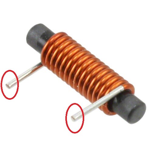
How to build your own Above Unity Machine

  • Topic Is Sticky
  • 11K Views
  • Last Post 04 November 2023
Chris posted this 01 December 2018


You Will need:

  1. One Input Coil
  2. Two Output Coils
  3. Patience
  4. Support


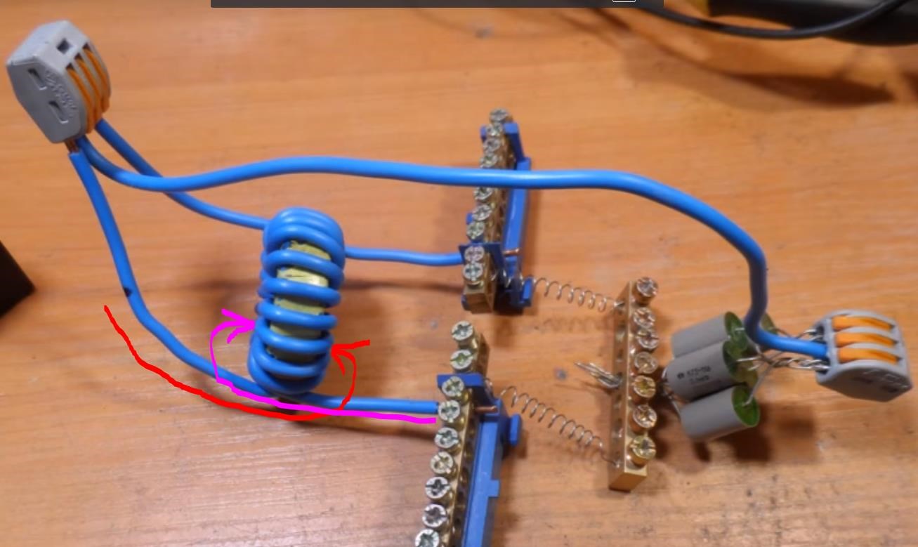
You need to follow the basic plan laid out here:


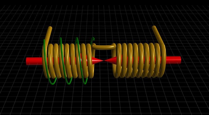
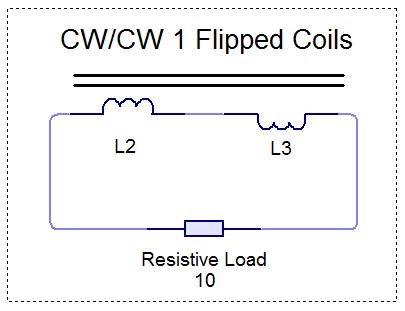
NOTE: Partnered Output Coils can be wound either CW / CCW or CW / CW Flipped.

  • CW is Clockwise.
  • CCW is Counter Clockwise.


I prefer CW / CCW.

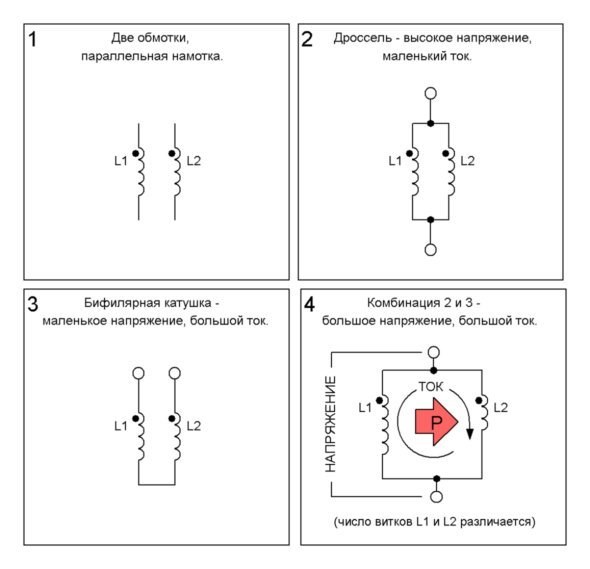
You will need to make sure your Output Coils have Opposing Magnetic Fields, thus Opposing Currents! 


This is a Critical and Required Component!


The Operation to start with is as follows:

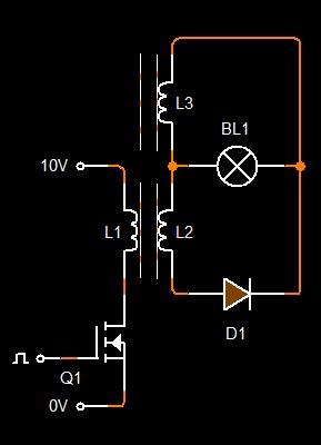
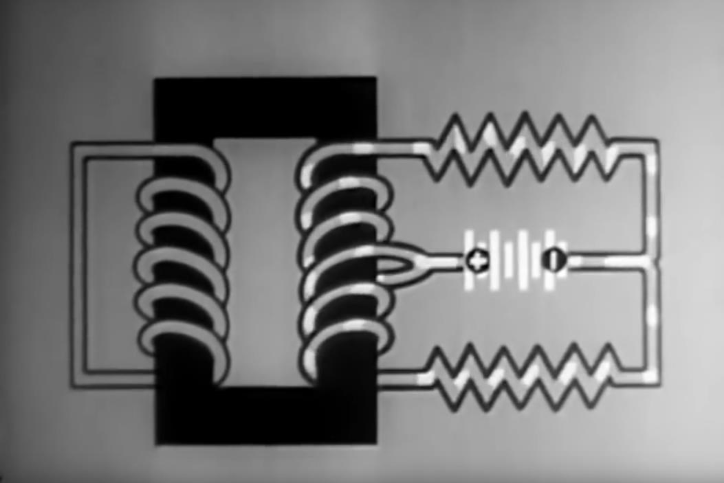
  1. Input Coil ( Green Coil ) brings up the Potential, then is switched Off.
  2. One Output Coil then Conducts Current ( Gold Coils ).
  3. The Second Output Coil then also conducts Current, a split second after the first, Equal and Opposite, to the First Output Coil ( Gold Coils ).


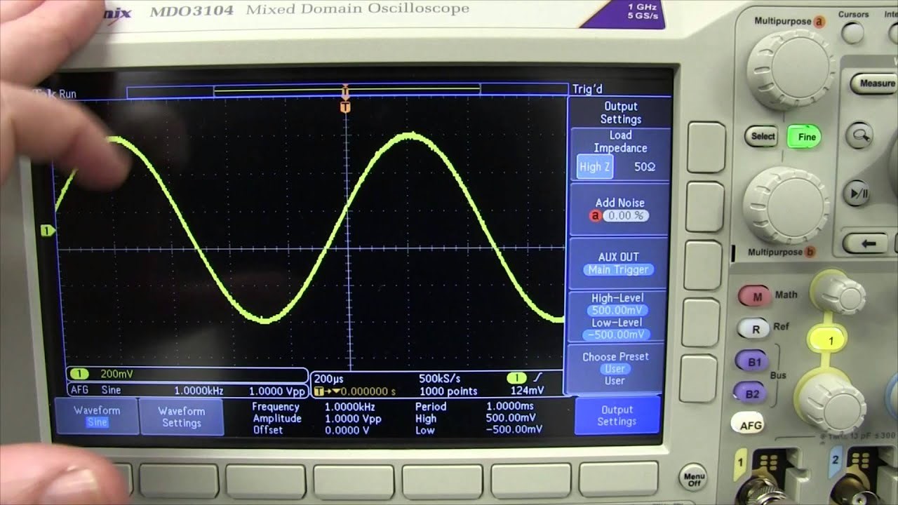
INPUT: Go for 2 Volts DC and around 320Hz or so, a Duty of around 10% or so. Slowly turn the Voltage up until you see things start to happen.

You will need to make sure the turns are greater on the Output Coils, per Coil by a factor of at least 1 : 3, so for every 1 turn on the Input Coil, you will need 3 Turns on the Output Coil and then that again for the Second Output Coil.

NOTE: Sometimes dropping a few turns on one Partnered Output Coil can be of benefit.

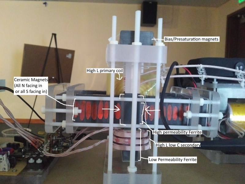
A small Gap between the Cored Partnered Output Coils to delay the Magnetic Field Mutual Coupling between the Coils. Circuitry can also be employed to delay Conduction on the second Partnered Output Coil.

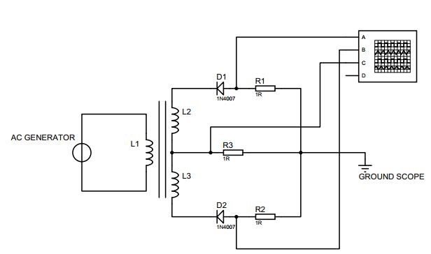
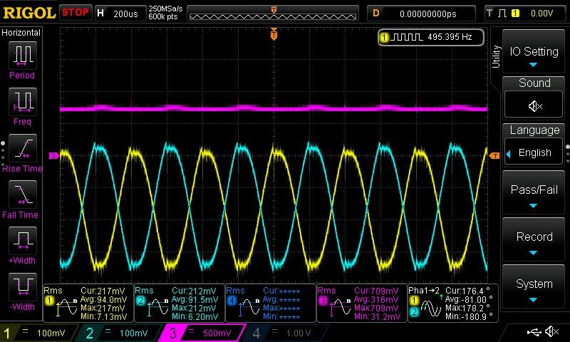
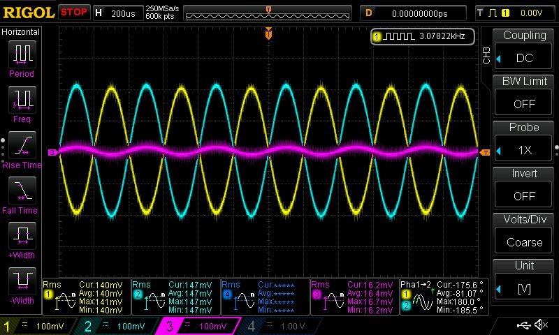
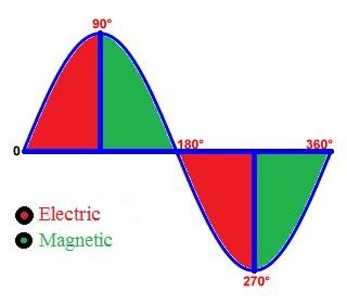
Monitoring Currents in the Partnered Output Coils, you will see the Partnered Output Coils, like The Mr Preva Experiment, will Oppose, Magnetic Fields will Oppose! The Machine works because the Fields Buck, a Bucking Oscillator!

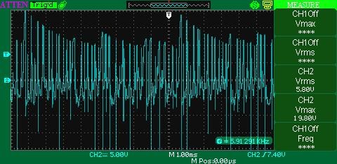
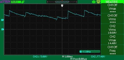
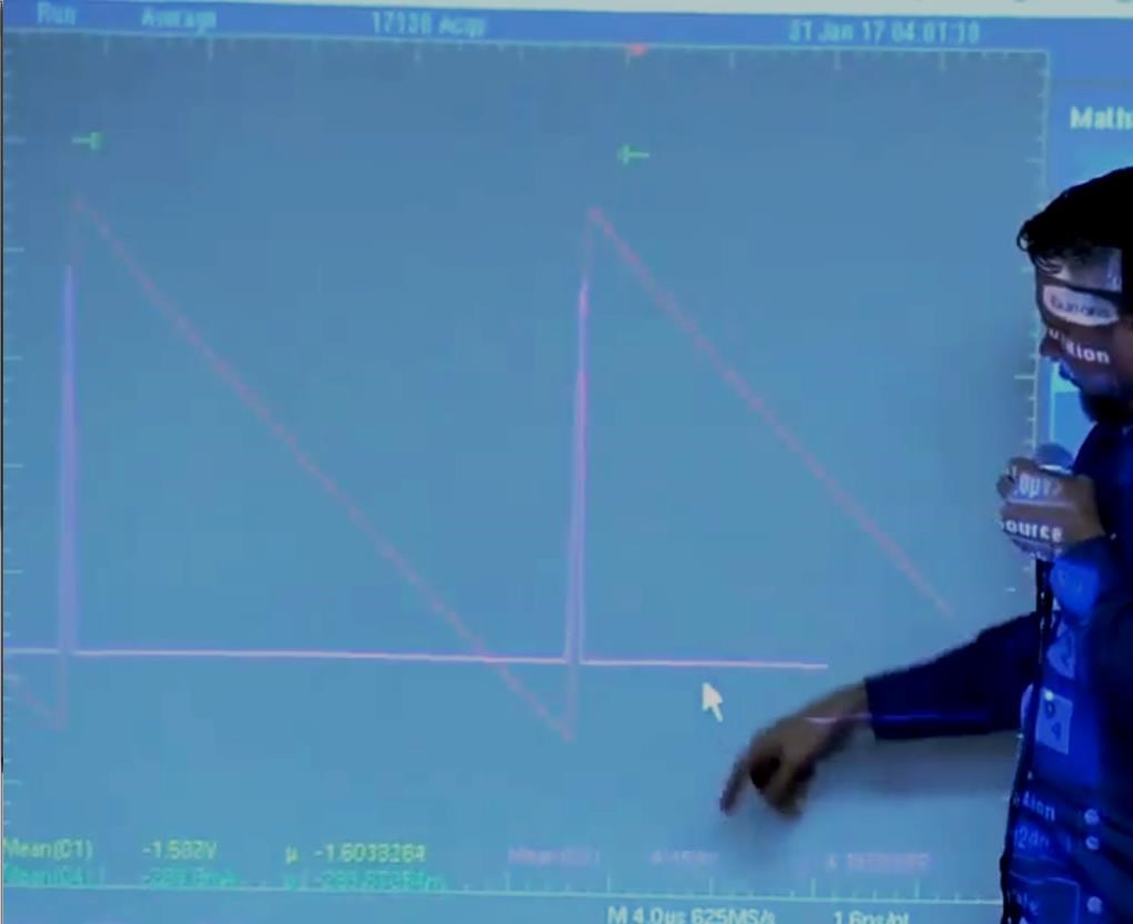
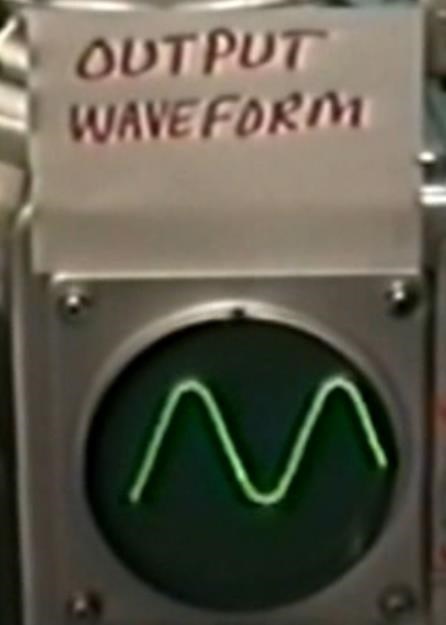
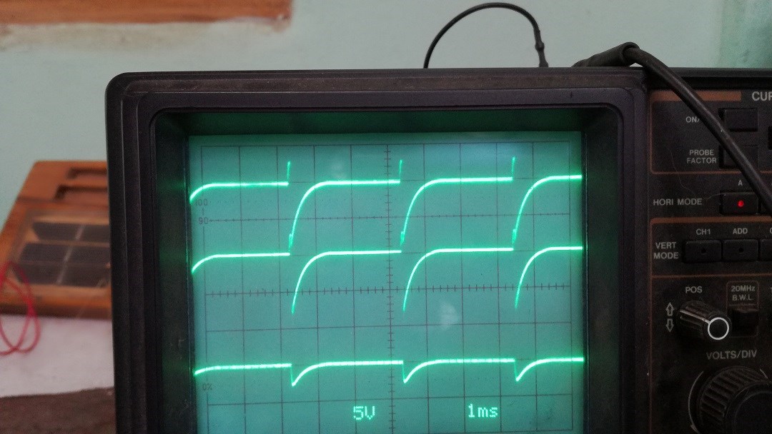
NOTE: When you have Bucking Output Coils, you will see a Sawtooth Waveform! Look for it, its the sign you need to see to know you're getting results.

Now, its up to you, arrangement, how you Construct it. I suggest Small Cheap and easy to work with!

On your Input Coil, perhaps use 12 turns 1mm wire or slightly larger. This means your Partnered Output Coils will be approximately 36 Turns each give or take.

NOTE: Don Smith suggested 1 : 4 Ratio.

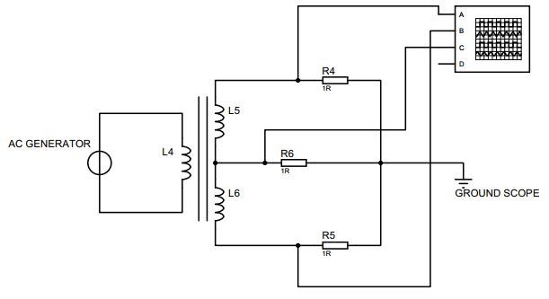
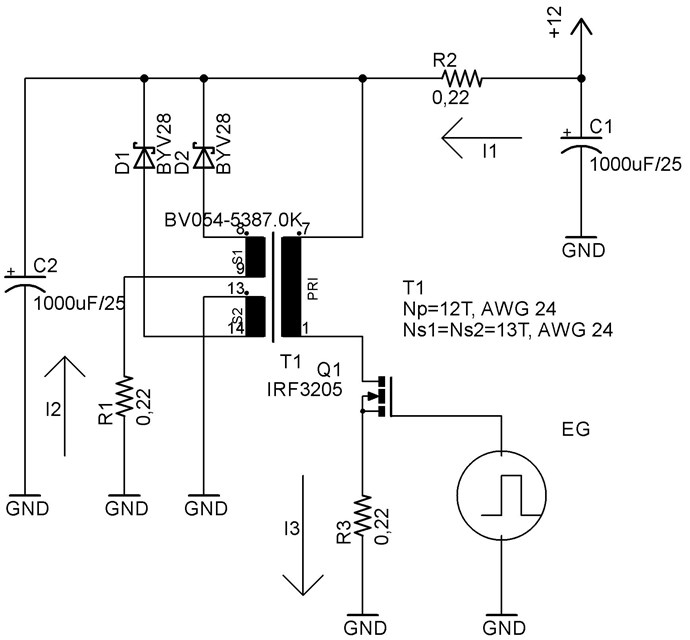
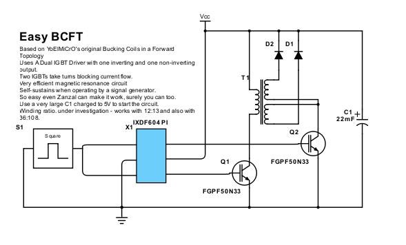
I have suggested a few Circuits already:


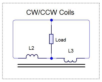
Of course, this is what I have found, and the Output Circuit is not limited to these Circuits specifically!

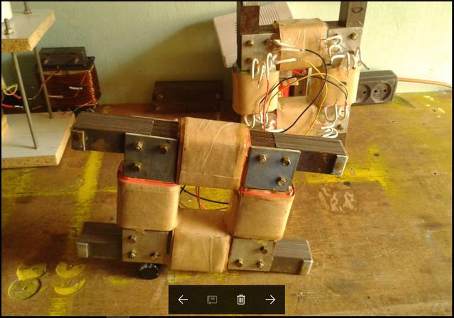
Look at the Independent Replications, for some inspiration:


  1. Bill Alek
  2. TinMan, Bradley Richard Atherton.
  3. Graham Gunderson.


Basic and up Front, No Bucking, then your machine does not work and you need to re-arrange your Machine.

This is an Asymmetrical Machine, all this I have covered here on my website. We have:

  1. Amplified Voltage. Turns Step up.
  2. Amplified Current. Bucking Magnetic Fields as in The Mr Preva Experiment.


For all we have covered, all of it, and if you've followed, then this task should be easy!

I Promise You, if you follow the rules, make your Machine do what I have said above and on my Websites, it will work. You will have an Above Unity Energy Machine! You have my word on it!

   Chris


NOTE: I expect you are experienced enough to competently work with Electrical Energy! This device can be dangerous, High Voltage and Current can very easily be achieved! I am not responsible for harm to person, and or equipment! I give you this very simple Guide as is and without warranty or guarantee. I have given a promise, and if you follow the instructions, this will work as I have stated! Making Changes will result in Failure.


Order By: Standard | Newest | Votes
alohalaoha posted this 09 January 2019

Hey Chris - check these new topics from Vyacheslav Gorchilin site

Slow drift magnetic waves in Partnered Coils Configuration

http://gorchilin.com/articles/coil/magnetic_wave?lang=en

and this one

2nd order magnetic wave resonance math in PC configuration

http://gorchilin.com/articles/coil/magnetic_wave_resonance

The Trure Partnered Asymetric Buck configuration

  1. Two coils conf., parallel winding
  2. Choke conf. - high voltage, low current
  3. Bifilar conf, - low voltage, high current
  4. Asymmetric Partnered Buck conf. - high voltage, high current. Remark. Coils need different wire lenght.!

Regards

Aloha

Chris posted this 29 December 2018


Chris

Gravitation posted this 01 February 2019

Ok from what i see, it seems to be good to have diode in reverse at the output branch of the Mr Preva experiment to force current to flow only in the center of the coils. When diodes are there, the sound of the transformer is deafening. And i am very suprised that the current in the center is almost pure DC without capacitors. Watch pictures

The frequency on the scope is wrong, i was at 2500Hz on both shot. Notice that the current monitored in A & B (on the scope) were negative DC and the 1 ohm resistor (R3) was positive DC.

With diodes :


Without diodes : (the transformer makes a little sound, nothing compared as before)

Next step is going to put some capacitors to reach resonance and see what's will happens

Chris posted this 01 December 2018

Aloha,

This is a key Patent: TESLA PATENT 336,961 REGULATOR FOR DYNAMO-ELECTRIC MACHINES.

If, for instance, the commutator-space between the brushes a and c, when the latter is at the neutral point, is diminished, a current will flow from the point Y over the shunt C to the brush b, thus strengthening the current in the part M', and partly neutralizing the current in the part M; but if the space between the brushes a and c is increased, the current will flow over the auxiliary brush in an opposite direction, and the current in M will be strengthened, and in M' partly neutralized.


More than 100 Years old! dated March 2, 1886!

We already know this is specifically related to the Amplification of Current:


The Greatest man that ever lived, Nikola Tesla, the Mr Preva Experiment with Don's video, is undisputable.

   Chris

Chris posted this 27 December 2018

My Friends,

For those that don't already know this, another way of thinking about the Partnered Output Coils, how they work and interact together, is:


You can see, L1, your Input Coil is pulsed at Frequency and Duty Cycle X, which is a sub harmonic of the actual Magnetic Resonance, It has coupling to L2, but not L3. L1 is switched off. The Magnetic Field created now moves from X to zero. At the point of induced voltage of about 0.5 volts, the diode: D1 will conduct and the bulb BL 1 will light.

Now, importantly, the close proximity of L3 to L2 means the two coils will interact together. The two Coils buck, simply because their reactions together invoke Faraday's Law of Electromagnetic Induction. This geometry will add, the Current as we have already learned in The Mr Preva Experiment, will double the Current in L2, and gives us L2 + L3 Current in total, remember, Floyd Sweet told us the same thing:

In the specific case of positive charges moving to the right and negative charges to the left, the effect of both actions is positive charge moving to the right.

Current to the right is: I = da+ / dt + da- / dt.


Negative electrons flowing to the left contribute to the current flowing to the right.

These interactions on the Input cost us very little. A short sharp pulse brings up the Potential on L2. That's all that's needed, the potential to be bought up! Nothing else.

Then, the pumping action, the pressure, forces the Charged Particles as current down the Insulated Copper Conductor and out to the load.

Its not all that complicated, but a definite way of thinking is required! A clear mind is required.

   Chris

Chris posted this 28 December 2018

My Friends,

Something to keep in mind, Input power can be wasted and is often wasted, because the machine control is not quite as ideal as we may like.

The best example is in Brads Rotary Transformer. Remember, you need to catch the wave, Frequency and Duty Cycle is required to get the correct Subharmonic:


You can see, all the spikes in there, the spikes after the first peak at the top of the Sawtooth Waveform, all the spikes are wasted energy after the wave for has been caught. On the other side of the diode:


We see, the Sawtooth Waveform is not clean, its all over the place. We really need to aim for a clean evenly distributed Sawtooth Waveform. Graham Gunderson was one of the best I have seen:


Seen in red, the Sawtooth waveform is the Asymmetrical Regauging. We have covered this in some detail in my thread: Asymmetrical Regauging

This is Electrical Energy "Generation" at ZERO COST to your Input. It is entirely between the two output, the Partnered Output Coils.

   Chris

Atti posted this 01 December 2018

   Hi. 

 I fully confirm Chris's writing!  Chris has perfectly summed up the building criteria, the opportunities to find work in the work of others.

 But!!

How much energy do I spend and how much can I get out of it? Are there any measurements in and out of this? How much is the difference?  Did anyone make a similar measurement? Just out of curiosity.

Chris posted this 14 December 2018

My Friends,

I would remind you, all the information you need is in the first post.

Following the instructions, with a little persistence, you will learn amazing things.

   Chris

Jagau posted this 28 December 2018

I have no doubt in my mind that what Chris teaches is exactly what we have to do. It is up to us to develop from this concept.

You must not wait to have everything cooked in your mouth and simply copy the result.


I am a little surprised by your reactions, lets go at work. Magnetic resonance is what we have to work on, let the electric resonance drop.

I am making a very explicit video to prove what Chris taught me to do.
You will understand then that he was right.
Jagau

Vidura posted this 10 January 2019

The information from Gorchilin is very recomendable to read for understanding  of the magnetic resonance.

Regards Vidura.

Zanzal posted this 13 January 2019

Hey glennmr2018,

Welcome back. A couple of suggestions from experience:

I recommend avoid sharing ideas that you haven't built in someone elses thread. Its white noise that most experienced replicators have learned to simply ignore but it can be annoying to the thread owner who is trying to convey an important concept and doesn't want their thread filled with unproven attempts to innovate. Proven innovation is always welcome.

From experience I can tell you that if you haven't already built a working POC any innovation on the idea is a waste of time. There is an order to things in life, first you must learn the working principle, then you can expand upon that principle and integrate other principles.

Start simple with Mr Preva replication. If you can replicate the concept behind MrPreva then feel free to share your replication of that experiment (if you have not already.) Its sort of a right of passage and its the very important principle behind what Chris teaches here. Its not a concept you can skip and expect to be successful.

You should look back and delete any duplicate posts you may have made. Chris may do this for you.

Anyway, that's just some advice, you can do as you wish. Feel free to update us on how your idea works out.

Chris posted this 29 January 2019

Hi Gravitation,

Thanks for sharing! Welcome!

If I may point out, your Current is correct but in reverse. When one Pushes a Ball Up a Hill, One does not want any Resistance, one wants a task that is easy as possible.

We must not interfere with the Magnetic Field on the Up Hill journey! We must allow the Magnetic Field to build to maximum value with Zero Interference.

Where we want to use the Magnetic Field is on the Down Hill Journey:


Excess Electrical Energy can only be "Generated" by a Changing Magnetic Field! A Changing Electric Field burns a Heat Death - See Don Smith Quotes.

So, when a system is transforming from Electric to Magnetic, one must not allow any interference!

When a system is Transforming from Magnetic to Electric one can use the Changing Magnetic Field to "Generate" an Excess. Only using Partnered Output Coils however, not possible using a Single Coil.

The Partnered Output Coils must have sufficient Voltage and as a result Magnetic Fields ( Opposing Currents ) to see gains. Some work is required here to maximise your systems Energy "Generation". Some threads that may help: Asymmetrical Regauging, Magnetic ResonanceImpulse Pressure Wave, Non-Linear Inductance, Electromagnetic Waves, Increasing the Rate of Kinetic Energy, E=mc^2, Nano Second Pulses, Charge Separation, Resonance, Force, Parallel Wire or Bifilar Coil Experiment, Lenz's Law Experiment, Reduced Impedance Effect, Timing, Parametric Excitations of Electric Oscillations, Some Coils Buck and some Coils DONT, Accelerating Electrons, Electrical Energy...

Two Magnetic Fields ( Partnered Output Coils ) Slapping together very fast "Generates" a Voltage higher than two Magnetic Fields Slapping together Slower:


Ref: https://www.youtube.com /watch?v=xvNNTc6ZPtQ


Magnetic Fields Stand the same as Ocean Waves Stand:

Ref: https://www.youtube.com /watch?v=EUXOZAinUPk


A Vertical Wall of Water, huge Force.

NOTE: This Wall of Water is the Amplitude of the Voltage Peak! Voltage is bought high, because of the Magnetic Field Change! This is the Regauging part, seen here:


You are on the right track, but just have the Currents on the wrong side of the Cycle.

   Chris

Gravitation posted this 30 January 2019

Many thanks for the super precise answer ! Very good idea to have listed all the threads that can help ! Vidura, yes i confirm to you that my coils were opposing magnetically in this screenshot.

It is very clear for me now, i will continue on the way that you said and post some news later


Chris posted this 20 September 2021

Hey Scalar wave interference,

When you say:

Is it necessary to input positive and negative sharp pulses on the input coil?


The answer is no, it is not necessary. Only a Positive going Input Pulse is required.


When you say:

Is there a time interval between positive and negative pulses?


Youre getting ahead of yourself, focus on the machine and what it is doing and what it needs to do,


I now use the MR.fighter method directly. On this basis, can I add an input coil so that the secondary double coil can generate sharp pulses?


Again, focus on the machine and what it is doing and what it needs to do. In these machines, resonance is very important, and I believe you have not hit resonance yet. Try not to get ahead of yourself, concentrate on the machine and what the machine is supposed to do. The fine details are very important, missing steps will result in failure.

 Best Wishes,

   Chris

Jagau posted this 01 December 2018

The model to use is very simple Aloha, everyone can do it.
Take a pot core with 3 cables twister set of gauge 24 or what you have on hand, 2 cables are in mode P.O.C. and the third in Rx
With a signal generator injects about 5 volts p / p in order to
find the frequency of resonance when you have found injected into your POC and look at the exit you will be surprised at the result.
Adjust the voltage of the S.G. up to 300 mv p / p and you will still have a lot of voltage present. It is a (C.E). cold electricity, .but with an avramenko plug I turn on up to 5 leds without extra consumption.

P.O.C. configuration is the name of the game it is a must

Jagau

Chris posted this 09 December 2018

Thanks Jagau!

Those that read these pages will notice some similarity in the ideas presented. There is some base level items presented in the 'What's it going to take to get OU' that we have seen in other devices.

Graham Gunderson used Permanent Magnets to try to Bias the Core of his MIT to get up to close to the Knee of the BH Curve, Ironically, I used this requirement in my document. Ironically, Bucking Coils I have been presenting for many years, since 2011, Graham Gunderson used Bucking Coils.

Thanks to Reiyuki


Graham deserves full credit, he did an awesome job, and an awesome demonstration! I could not have ever done such a professional demonstration. Even though he did use all my work. Only a few years earlier, stating he did not look into interactions of Coils and had only investigated Floyd Sweets Permanent Magnet Conditioning, which was a Hoax and a Lie.

Yes I have had some communications with Graham and his team members over the years. I did share Floyd Sweets Transcribed Lab Notes with the Aseop Institute and we had some communications as a result. All readers should research this story.

Mark Goldes never released any documentation on Floyd Sweet. I asked a few times, he told me he had none.

Graham Gunderson worked for Mark Goldes for many years.

Mark Goldes had on the order of 50 companies, all going either bankrupt or closing. Companies including: ASEOP, MPI, Chava… and others. Mark Goldes, then ASEOP Institute, funded Floyd Sweet, some of the equipment in images of Floyd Sweets demonstrations was funded by Mark Goldes, but not all:

Mark Goldes, Co-founder of Chava Energy and Chairman of Magnetic Power Inc. and its synergistic subsidiary company, Room Temperature Superconductors Inc. Chava is acquiring assets of both the earlier firms.


Magnetic Power Inc. Company assets are being acquired by Chava Energy. The new website is http://www.chavaenergy.com/ Devices formerly called Magnetic Power Modules(tm)are now called MagGen(tm).

Chava is developing these modules as well as other breakthrough technologies.

As of the Summer of 2009, Mark Goldes claims to have achieved several over-unity protypes, and hopes to have commercial 1 kW units ready next year. The company claims that those with an EE background and with an open mind will agree that the concept (disclosed under NDA) is workable.

For those who do not have access to proprietary photos, videos, and other evidence due to the proprietary nature of this technology, confidence is borrowed from CEO, Mark Goldes' reputation with Ultraconductors, a known and proven technology.


Some well known names worked for Mark Goldes:

  • Cyril Smith ( Smudge )
  • Partzman
  • Graham Gunderson
  • Others I cant think of at the moment.


If my research is correct, Mark Goldes never once produced any Product, no Product ever went to market.

Suppression comes in many forms, sometimes suppression of technologies, appears in the form of business Failures. Those working for the System, not realising they are part of the problem.

Note: Almost every page out on the Internet, when Searching Mark Goldes, contains the word: "Swindle". Mark Goldes has earned a somewhat dubious reputation.

   Chris


Chris posted this 12 December 2018

Hey Aloha,


No, no, no, no, High Voltage ( HV ) is not a requirement!


In some machines, as little as 3 volts is all that's required!

The rest you have mostly right. Timing, we must have the Partnered Output Coils interact at the right Time. Remembering, we have the already known Magnetic Isolation at this time in the Cycle:


The Primary Coil see's no Negative effects from Lenz's Law, but only at the right time. Of course each Partnered Output Coil is its own Battery, Voltage is produced by the Input Coils Pulse, but Current is a function of Loading the Coils at the right time, the Opposition of Magnetic Fields increases the rate at which Current can flow to the load.

The following video shows some techniques for the timing:


Those that have been reading and following would already know all this.

I see, we are in for a work load of avoiding Confusion. We must, absolutely eliminate these statements that introduce elements of confusion for readers.


Aloha and others reading, I want to make a point of saying; Please do not make statements unless you are sure of the correctness of the statements!


Thank You,

   Chris

Vidura posted this 12 December 2018

Chris ,

you mentioned in this post the importance of getting the strongest possible magnetic field in our devices, I completely agree with that and want to remark the importance of the coils design for this purpose. Sometimes we want to make it easy , use small nr of turns for our coils, which sometimes might be correct, specially for HF applications, But regarding the Ampere turns and field strength it is good to keep in mind the following investigation results from Joseph Newman:

Quote from Patrik Kellys book:

Consider an air-cored coil with an interior diameter of 10 feet, a height of 8.32 feet and would with 1,000 feet
of 40-gauge copper wire. That length of wire has a resistance of 1,049 ohms and weighs 0.02993 pounds.
If 100 volts DC is connected across it, then a current of about 95 milliamps will flow, which is a power input of
9.5 watts. With just 31.8 turns, it will produce a weak magnetic field of 0,012 Gauss, with a mere 0.000014
Joules of energy stored in it. With a tiny inductance of just 0.003 Henries, if the current is stopped and the
ends of the coil shorted together, only an insignificant current would flow.
Now, repeat the experiment, but this time, use 5-gauge copper wire. As it has a resistance of 0.3133 ohms
per 1,000 foot length. To equal the same resistance and match the previous current flow, a massive length
of 3,348,000 feet needs to be used. This length of wire will weigh 335,469.6 pounds which is 16.77 tons.
The 10-foot interior diameter coil, 8.32 feet tall, wound with this wire will have about 90,000 turns. If 100
volts DC is now connected across the coil, the same 95 milliamp current will flow with an input power of 9.5
watts, the same as before. But due to the massively larger coil, it has a magnetic field of 23.7 Gauss, which
is 1,905 times larger than the previous coil, and with 116 Joules of energy stored in the magnetic field. This
is a phenomenal 8,000,000 times more energy than in the 40-gauge coil of the previous example. A
phenomenally larger current flow would now occur if the current input was stopped and the coil shorted out,
as that would generate an inductance of 25,700 Henries which is more than eight million times the
inductance of the previous coil.

The values in this comparison are extreme, but Joseph built then a prototype motor with "only about 2 tons " of copper and run a 600 pound PM rotor with 1.5 W of power consumption and a huge excess energy and strongest BEMF spikes.

The point I want to remark: we certainly will not be able to spend money in this amount of copper, but increasing the wiregauge and nr. of turns by a reasonable factor might increment the performance of our devices very notably.

Regards VIDURA.

Chris posted this 27 December 2018

My Friends,

Some things should be burnt in, these words are the most important:

Don Smith 2006 Tesla Tech (17:42)

Ok this is, something which I have a patent on, it relates to getting a huge amount of energy out when you put a few milliamps of energy in, you end up with like a hundred kilowatts of Energy out.

That won’t make sense for someone who thinks of an electrical system, you have to think in terms of Magnetic Flux, because, if you’re using electrical flux, everything is dying a heat death and you lose the energy almost immediately, in electrical flux, but in magnetic Flux you can make as many copies of the original as you want, without depleting the original at all, so if you’re chasing electrical flux, you’re chasing the wrong rabbit, you need to be chasing magnetic flux.


You need to build it, make your path straight, if you want it!

   Chris

Chris posted this 08 January 2019

Hi Fer123,

Excellent example! Yes, there is a component here that is the same! Andrey Melnichenko is one of my hero's! Remember what he went onto:


The last video is with Arthur Trankle from now Steho Energy showing the works of Andrey. Pin 5 on the 34063 IC is of very short Duty Cycle but many of them. this is in attempt to catch the wave.

   Chris

Chris posted this 08 January 2019

My Friends,

When building your Machines, remember you must account for a Inductive, Inductive Time Constant.

The Time it takes for the Bucking Fields to move from maximum value to zero is accounted for, the same as the Time it takes for the Magnet to fall through the Copper Tube:


Remember, what we are aiming for is exactly the same effect! Asymmetrical Regauging:


If you do not leave enough Time, after your Input Pulse, your Output Pulse will be insignificant, Asymmetrical Regauging, shown above requires a short On Time and a Long Off Time. You also must get your Timing correct so as to Catch the Wave down to Equilibrium or Zero. A Sawtooth Wave Form. Floyd Sweet showed a Sine Wave, but look how straight is sine edges were:

Ref: 25 : 51 - Floyd Sweet Secrets - Remastered - 13-06-2006 - 6.05 AM


Compared to a standard Sine Wave:


A visible round edge difference seen. The Straight edge shown in Floyd Sweets Scope Shot is the Asymmetrical Regauging. A DC Cycle each Half AC Sine Cycle.

   Chris

Vidura posted this 29 January 2019

Hi Gravitation and welcome. It's good to see new members joining and doing practical experience. The sawtooth wave is inverted in your screen shot. The current have to be at maximum value in the beginning of the work cycle and fall linearly or exponential depending of parameters. Check if your coils are actually opposing magnetically. Regards Vidura.

Chris posted this 05 February 2019

@All,

I wish to share some fantastic results!

Zanzal has replicated YoElMiCrO's Circuit and got some very good results!

Zanzal's Thread: Zanzal's Easy BCFT Circuit


YoElMiCrO's Circuit.


Zanzal's Circuit.


You see now, together we can change the world! We can! We have much more power than you think! You, here working toward the future will be remembered forever as the ones that led the Driving Force to make a Change!

Its all just a way of thinking, no Magic involved!

   Chris


EDIT: Zanzal has reported an error in his result, please check the Thread listed above.

Forelle posted this 22 February 2019

Hi all,

this is a short info how it goes on with my first bucking coil experiments,i did take 12 turns on the inputcoil,1,1mm dia,and 1 x 36 and 1x 33 turns on the buckingcoils,i was very impressed that i get with 2,8V and 0,8A a 1200 Vpp,accidently my load (lamp) was damaged and i was wondering why it did not light up and instead i saw about 5mm long sparks inside the lamp and very high spikes on the scope .This is not compareable with the regular spike that you  get with like for a Bedini system,if you imagine with only 2,8V and such few windings 1200 Vpp.

I would like to build a little bigger device where i can adjust the gap when it is running and where you can adjust the position of the coils.Chris,you never mentioned the wire size for the bucking coils is there a size that works better than an other?I forget, i had 10% dutycycle and 270Hz.

Oliver

Chris posted this 01 December 2018

Hey Atti,

COP > 1.0 when one has Tuned Frequency and Duty. Also with good Gapping and any Switching.

Crazy thing is, many here could build for $20.00 and an hours work if they know what they are doing.

Again for the readers: Critical Point is, Partnered Output Coils MUST Buck, this is the Current Amplification part. Greater turns on the Output Coils steps up Voltage, this is Voltage Amplification.


Very simply: Power ( P ) = Voltage ( V ) x Current ( I )

   Chris


P.S: Lets see, what we see, from those that have waited for this for an eternity?

alohalaoha posted this 01 December 2018

   Hi. 

 I fully confirm Chris's writing!  Chris has perfectly summed up the building criteria, the opportunities to find work in the work of others.

 But!!

How much energy do I spend and how much can I get out of it? Are there any measurements in and out of this? How much is the difference?  Did anyone make a similar measurement? Just out of curiosity.


Hey Atti

It is not important how much input power you will inject in circuit 10Wt or 100Wt. You will get as much energy as you need at output once process was started.

Aboveunity power comes from charge injector pump, or from ferrite core charges.Sources of charges could be different. High potential - high frequency devices like Tesla transformer, Vladimir Brovin's Katchers (with HV bipolar or HV mosfets or IGBTs), Ground, Indepenent mass of high conductivity metals, salt water, highly ionised air, plasma sources etc.etc.

Charges only need to be sucked by Bucking Magnetic Fields and boost their initialy field strenght. Process is autosync once has achived. As low impendance is your load as much charge injecting would occur. This device make with easy infinite rise of power. So you need to sink additional power or to lower injection rate.

ps: The most important thing here is a TIMING. All must be balanced and coordinated. Maybe Chris should start with design electronic logic control for all kind of assymetric devices ?

Reg.

Aloha

alohalaoha posted this 01 December 2018

I want to share these Tesla's words which have a great importance to all aboveunity researchers and inventors.

They were from the lecture delivered by Nikola Tesla to the American Institute of Electrical Engineers at Columbia College, New York 20 May 1891. Lecture was firstly posted in the electrical engineer, a weekly journal of electrical engineering, volume viii, from 3 July, 1891.

Quote Tesla"

I would call attention to the fact, that in an alternating electrostatic field, a conductor, such as an exhausted tube for instance (or any resonant coil, waveguide, any conductor my addition), tends to take up most of the energy, whereas, in an electromagnetic alternating field the conductor tends to take up the least energy, the waves being reflected with but little loss. This is one reason why it is difficult to excite an exhausted tube, at a distance, by electromagnetic induction. I have wound coils of very large diameter and of many turns of wire, and connected a Geissler tube to the ends of the coil with the object of exciting the tube at a distance; but even with the powerful inductive effects producible by Leyden jar discharges, the tube could not be excited unless at a very small distance, although some judgment was used as to the dimensions of the coil. I have also found that even the most powerful Leyden jar discharges are capable of exciting only feeble luminous effects in a closed exhausted tube, and even these effects upon thorough examination I have been forced to consider of an electrostatic nature.  How, then, can we hope to produce the required effects at a distance by means of electromagnetic action, when even in the closest proximity to the source of disturbance, under the most advantageous conditions, we can excite but faint luminosity ? "

End of quote

Jagau posted this 02 December 2018

Hello Aloha


I am in this forum to learn, and with my latest research I share with you the little things that I find

because this is the purpose of this forum.


share what would be interesting
learn to share it
help those whom we can help.


No I have not found the rosetta pearl yet but I'm working on it.

I hope I did not disappoint you, but you bring me ideas that sometimes move me forward.

Jagau

Chris posted this 03 December 2018

Hi Aloha,

I think, think Simple.

Follow the first post, don't change anything, make the goals and there will be no confusion.

Yes, we do have a small few here, waiting to thieve the good bits.

He shot out of here like a scolded cat when he saw the thread I left him!

Note: Some members here, English is not their first language, and they wish to stay quiet readers. They would never have trouble here! But I understand their position.

   Chris

Vidura posted this 03 December 2018

Hi Chris
Yesterday I have lost a detailed post, so i have to edit in another program and paste.Maybe i should have formulated my last post as a question, i am aware that you have tested this for many years. So yesterday i had made some experiments using your guidelines , where i tried different configurations, like in the posted schematics and reversed with and without airgap, diodes and so on. I found it actually easier to get a significant output connecting the way like in the schematic, but using the right hand rule the fields are not opposed like poles. Neither they are in the Mr Preva experiment, in this cases the fields are allowed to align as unlike poles, and they are forcing the current to flow from the lower to the higher potential side. In my test setup i got this way a exponential current curve, not a sawtooth. With a airgap the interaction least much longer. Also the diode helps in this case, without it the pulses become very short and sharp, and the input power increases.

Anyway i think the diode is not strictly necessary when the coils are tuned correctly in resonance. When connected the other way , so that fields are forced for opposing like poles there is a very notable reduced impedance as expected, but i still could not get out a significant power level on the output. The spikes are very sharp and short and don't make lit a bulb. This could be due the small nr of turns of the coils, so i rewound one with more turns-more inductance, which i still have not tested. Regarding your question: thanks for asking, sincerely i have not much progress lately. Maybe due to problems in daily live I hardly can concentrate well in the investigations. Such is life sometimes , then it will change for better again certainly.

Vidura.

Chris posted this 03 December 2018

Hi Vidura,

Sorry about the loss of your post. The session of your login timed out. There is an App Pool issue I am still trying to resolve.

My life is full at the moment also, problems unexpected. You're right, better it can only get.

-------------------------------------------------------------------------------------------------------------------------------------------

Yes, Yes, the exponential curve is right, that's good!

Voltage will be the Sawtooth wave, it is a linear reduction, fall to zero, due to the opposing Currents.

Diode is good, it creates a delay, ever so small, some are in the nanoseconds, but it can be enough in some situations.

You could always load each coil separately?

The same result will occur.

Also, sometimes, stay safe doing so, but increase input voltage just a little. 

Excellent Vidura! You're on the right track! Like the Mr Preva Experiment, there is no difference except we are using a low impedance Coil to drive this arrangement to increase Voltage, to test the result, hook the Coils in Series and see if the Current has doubled? If not, the Currents are not Bucking. 


This was the device that I shared with everyone here: Bucking Experiment Way back on April 16, 2014


It was the next step, driving with a separate Coil. Sorry for the mess in the video. It was a very busy day.

Remember where Floyd Sweet started:


The BIG sponge trying to damp vibrations!

Remember, we must have Bucking. At the right power level, with cores, you should hear or feel a definite vibration!

   Chris

Chris posted this 03 December 2018

My Friends,

Listen carefully, what do you hear?


   Chris

alohalaoha posted this 11 December 2018

Hey Atti

Take one toroidal core for example from old pc power supply, which was used there as output choke. It is a big yellow ferrite.

Than make full bucking configuration like Mr.Preva did. Look from the aspect of cross-section of toroid. Wind two windings in opposite directions. It means one going from outer circumference of toroid through the toroid hole, while other going first from hole and end up on outer circumference.

Make it fully symmetrical with same number of both coil windings or if you like make asymmetrical. Then short both coils, add parallel resonant capacitor, two current sense resistors 1ohm or 0,1ohm (non inductive) and excite it with signal generator to catch parallel resonance. When you hit it, meassure RMS currents and voltages across both resistors. You will get the same like Mr.Preva have.

I can advice you to use litz wire for both windings. You should distinguish between 3 modes you could get.

1st. Partnered bucking effect.

2. Parametric resonance effect and

3. Acoustic resonance effect.

Our goal is to examine experimental conditions for obtaining 1st effect. According to experiments there is C.O.P = 37 or 3700% amplification of voltage and current. Both depend of lenght of coils or precisely lenght of wire wounded coils. Also if you use HF you need ferrite with low magnetic permeability, if low freq with high magnetic permeability. You can eaither pump the coils with the spark from your power supply or with mosfet or bipolar transistor. Anomaly bucking effect exist 100500%, only you need to catch it up. Also you may try with two air gaps in toroid to avoid satuaration of the core.

Best regards

Aloha


Chris posted this 12 December 2018

My Friends,

On January 23, 2015, I gave an encounter with a Vacuum Cleaner:

About three years ago I got the Vacuum Cleaner out to do some Vacuuming around the house. (Yes I do it regularly )

I plugged it in, went to turn it on, and POP! I thought this was very strange!

Pulled the Cleaner down and tried to find what was going on. I found that one of the Field Coils had blown itself to bits, approximately 1 cm of wire gone. Minimal Burn Marks!

The Rotor was stuck in one position, it could move but not freely like normal!

With my work I was doing (Related topic) I could only come to one conclusion why this happened.

I believe that the same situation as we are looking at right now had presented itself in the Motor! Magnetic Field's Build, some in opposition, and because the Rotor was stuck, we got Max Fields!

On collapsing with the sine of the mains I believe this Magnetic field went to Max Current and as a result the wire could not handle this huge current and it blew to bits.

I have of course assumed that this was the situation! I have no proof that this is what happened.

So, the point of me posting this, is that we need to Maximise the Magnetic Field Interactions! Get the highest Magnetic Fields in the device that are possible.

Ref: Partnered Output Coils - Free Energy


June 19, 2015 Bradley Richard Atherton demonstrated exactly this, a Vacuum Cleaner motor using Partnered Output Coils producing excess energy.

Study closely the Coil Interactions, there in lays the secret.

   Chris

Chris posted this 13 December 2018

Hey Vidura,

Yes, keep your machine small, easy to work with, keep the costs down while learning.

There is no need for huge field strengths like that, anywhere from 1 gauss to 1000 gauss should be more than enough. That is a very good example of how one can increase the Field, the Inductance.

   Chris

Chris posted this 13 December 2018

My Friends,

Stick to the outline I laid out in the first post!

Don't let complication creep in! Simplicity:


Pay special attention to the Terminals of the Coil, Pay special attention to the Terminals of the Coil, Pay special attention to the Terminals of the Coil, this is where you learn.

Introduce one Coil at a time.

Focus on the Voltage and also the Current! Learn how Interactions between the Coils can increase quantity's, eg The Mr Preva Experiment.

In-front of you is your goal should you choose to learn and take on this task. Ignore all outside distractions, focus on the task at hand.

For you, another replication, back in 2011: Sergey Dobrozhansky

   Chris

alohalaoha posted this 13 December 2018

Thanks Chris for pointing us on this great experiment by Sergey Dobrozhansky.

https://sites.google.com/site/dobrojanskij/soobseniebezzagolovka-2

Chris this is amazing. He take out 840W (1200V, 07A) at output coil loalded with 30K 2Wt resistance, while his input have had only 20Wt. It is C.O.P = 42. And all of this with small toroidal ferrite.

He has wwo pairs of bucking partnered coils on a torodial core with magnetic permeablity 6000.

Low voltage direct current to alternating current with further high direct current output. All of this with small battery. This is how he has called his setup.

Two primary coils from 15-30 windings - optimal number of turns 16-20.

Two secondary coils each 10m long. Maximal lengh depend only of toroidal core size.

He also sais that his primary coils were in bucking configuration Picture had not drawn correctly. One primary should be CCW (from core's hole to outer circumference and other vice versa CW.

So he had 2 pairs of bucking coils in his HV generator. Output of two partnered secondary is very high 1200V, 700mA, with only 10m of wire each. This is extremely dangerous voltage and could rise in several KV if you plan to use higher magnetic permeability core. For example some with 100 000 permeability 


Reg.

Aloha

Chris posted this 20 December 2018

Hey Vidura,

Like anything, experiment proves points. The shape, the geometry, yeah a role is played, but the shape of the Copper Conductor, as long as it is coiled, a helix, then the shape is not all that important.

History proves standard coils with standard Copper conducting wire is all that's needed.

   Chris

Atti posted this 21 December 2018


Hi.

Árpád Bóday's device has given more energy when I loaded it in its own arrangement. This resulted in asymmetry within the transformer. Only then did the permanent magnet refuse to operate. But within the transformer columns, not only your partner output coil is located, but the Mr Preva layout too. (for easier understanding) Due to the two transformers, parametric excitation can be imagined.
So you can see that others have used these effects.
Even if they did not deliberately make it so. But that's just my speculation. One picture about it.

Partner output coil operation in this old device also justifies Cris's explanations. Just think about it:
-asimmetric operation
- voltage excitation without any effect

This coil detects the magnetic field generated by the telephone student. It's so weird
monk, I mean there are two coils (bottom and top) because they are knock-offs.
If it were just a coil, it would not only take the student's changing magnetic field,
but would be collected from the environment by all other electrical equipment
also a disturbance, which is mostly a knock.

  To eliminate the knock, two coils were queued
bound but contradictory beginning - ending.

With this solution, the remote network
the whirlwind is extinguished. Conversely, the "top coil is closer to the student of the phone"
so his sign is not extinguished by the reverse coil. Very neat!  


http://oldradio.tesla.hu/szetszedtem/433kihangosito/cb55hoz.htm

Chris posted this 28 December 2018

Hi Atti, @All,

Yes, when people follow exactly, what I have laid out, the same exact instructions with "no improvements" from those that are not in the know, you will have an Above Unity Machine!

Some have had successes of varying different degrees.

   Chris

Zanzal posted this 28 December 2018

Please ask again. Has anyone already dealt with the layout? Could you share your experience?

I've already built my transformer according to Chris' specification, 20awg, 2x12 turn primaries (2 just in case I need to swap polarity), 2x36 turn secondaries. Armed with additional knowledge from my simulations I have on hand a slew of diodes I can switch between. In early testing with a Joule Thief configuration, I was able to elicit what I believe was a ferromagnetic resonance reaction my core. That's a good sign, but I know most ferromagnetic resonance reactions do not cause OU, but simply waste power while causing massive over voltages. Finding the island of stability can be challenging. I'll share what I find.


Vidura posted this 08 January 2019

A good point Chris, I have observed this waveform in some transformer tests, sometimes almost a triangular shape.

Chris posted this 13 January 2019

Zanzal is right,

That many posts of that nature should have their own dedicated thread. We are seeing a White Noise problem now. I urge new comers to start thinking about others, existing members.

I have moved Glenmr2018's posts.

   Chris

glennmr2018 posted this 14 January 2019

hallo guys~i have only just worked out how to actually view the latest posts here ~ by clicking on 'view latest posts' down below and scrolling down to the bottom!~ Chris , is there any easier way? this is why i posted the same thing 3 times last night~i could not even find what i had posted. While i apologize for this nontechsavy mistake.. i didn't expect you would delete the whole...lot! sigh!~i suppose this is 1 of the penalties i pay for having Aspergers Syndrome!

Visualize the Shape of Things Not Yet Seen with Eyes !! ... .. .

Chris posted this 01 February 2019

Nice Gravitation!

The Mr Preva Experiment is a step towards a working Above Unity Machine! Very nice waveforms there!

   Chris

Chris posted this 04 November 2023

My Friends,

Trolls and Traitors, you know, Humanities Lowest of the Lowlife Scum Bags, Bought and Paid for shills, have kept you away from the truth for a very long time, but the Community is starting to become better educated on this whole situation! Others observing what has openly happened to me, has been enlightening to most people, for the most part! Oh the Crap I have had to put up with from people, for so long! The list is extensive, the effort is mammoth, and the financial backing to get these people to do what they have, must be immense!


I have collected many Names, many entities, and many entities are from the same people! In other words, a small group of people, create many different usernames and flood the community with Complete Rubbish! Lies, Propaganda, just out right Rubbish! But, they make is sound believable, to lure you into Lies and thus Rabbit Holes that in the end, make you loose interest!

Thing is, its VERY Simple, very cheap and only complete dummies loose interest and start believing their rubbish!

Here:


People out there are showing you, all parts shown in this video and all videos, all machines, very cheap and very easily accessible!

It is only Dumb Asses that would have you believe in Magic or Vo-Doo Science, a Science that has absolutely Zero Credibility in actually Powering the Load... A very important aspect, and very simple once understood!

Voltage, via Charge Separation, and Current via the Freeing and Acceleration of Charge, the Free Electron, or the Elementary Charge, freely available inside the Insulated Copper Wire, Manipulated via Magnetic Fields, already explained and very well known:


Very simple, and the number of explanatory videos, I have given you, is also immense:


The Secret, I have already given you, thus why Members here have had so much Success!


Independent Replication is Scientific Proof:


Proof, and the Dumb Dumb Club cant see the Forest for the Trees! When too many Idiots flood the Forums, they make a mockery of the Truth! Right here, it's been here for nearly a Decade, you can SEE The Truth:


Start Here → Builders Guide to Aboveunity Machines

There are two mistakes along the way to Mastery: Not Starting and and not going all the way!

Cite: Master Shi Heng Yi

On rare occasions, Sweet saw this effect, called self-oscillation, occur in electric transformers

Ref: http://merlib.org/node/5282

The Answers you seek are right here:


I have provided 11 videos on this showing you how to approach this Technology! I have given you all of the data to make this work, and more, to make this, not just a TOY, to make this Power very much more than just a few Globes!

My Friends, when I see 10 successful replications, I will release another Video showing a bit more work, again we have had quite a few successful replications already! Do the Math in these videos! COP > 1.6 in both Machines!

Tinman was the first:


Others followed, like Captainloz:


Others also, some may not want their names used? Security for people is important to me, but eventually, we must do this as a Team and make a Stand!


We have Self-Running Machines, Our Flashlight that a Member of AboveUnity.com has achieved:


Aboveunity.com is Light Years Ahead of the other Forums!

Lighting up the Darkness!!!


We, www.aboveunity.com, is Light Years Ahead!

Oh My, there is a lot of complete idiots out there!

Best Wishes,

   Chris

Jagau posted this 01 December 2018

I confirm what Chris quotes above for experimentation.

In my last experience with two coils partnered Output coils (POC) and one input coil  that transmits at the resonant frequency

with only 0.300 millivolt p/p, I got 60 volts p/p. Make yours you will see, easy and cheap to make.

It's reality.

Jagau


alohalaoha posted this 02 December 2018

Thank for your support and many clever ideas Jagau.

You are a good american man, in same free energy problems like all honest people in america.

If you belive in my words, same situdation is at russia, and very probably 99,9999% in other parts of the world.

I know from my life way , only experiement is a supreme judge of all possible and impossible theories because he always present and show us a truth. This is the only reason why we need to listen him and analyse what he always tell us. No other way in total darkness of this parasitic world.

Best wishes

Aloha

Jagau posted this 02 December 2018

hi aloha


I'm 100% agree with you, it's very good,
just do not let go we'll have it.

Just a clarification I am Canadian

Jagau

Chris posted this 02 December 2018

My Friends,

I would like to quote:

Useful energy occurs as the result of imbalances in the ambient background energy, which is a transient phenomena. In the electrical field, it is a closed system subject to heat death, which severely limits it's utility. The flip side of the electron, produces magnetic waves which are an open system, not subject to heat death. These waves, being unrestricted, are the universal source of energy when unlimited resonate duplicates from this one source are available. Therefore, the key to unlimited energy, is Magnetic Resonance. In order to understand this, requires putting a stake through the Heart of Antique Physics. Non-linear and Open Systems are universally available in Magnetic Resonance Systems, Explosions of any sort [including Atomic Explosions] and Combustibles of any type. Mechanical equivalents would be levers, pulleys and hydraulics. A highly obvious example is the Piano where the Key impacts the one note giving one sound level, which resonates with it's two side keys providing a much higher sound level. Magnetic Resonance Energy clearly amplifies itself, demonstrating more energy out, than in.

Ohmic resistance does not apply to Magnetic Resonance which travels unrestricted for great distances, therefore multitudes of electrons are disturbed, and their back-spin translates magnetic into usable electric energy. The right angle component which the magnetic flux provides, translates into useful electrical energy. Taken at right angles, the Magnetic Dipole provides an unlimited source of electrical energy.

Don Smith - Resonant Energy Systems


Don't forget what we learnt in The Mr Preva Experiment! Magnetic Resonance, we know what it is already and already achieved it! We must get the voltage up, and this is how you do it!

Monitor your Currents! Like I showed you in the thread: Some Coils Buck and some Coils Dont

The Frequency and Duty you need to find, I believe you will find, is a harmonic of the Partnered Output Coils natural Resonant Frequency - Now I have said to much!

Now the Numpty Club will beat us to the Gold Nugget. Comon people, we have to be first!

   Chris


We're Light Years Ahead!
Members Online:
What is a Scalar:

In physics, scalars are physical quantities that are unaffected by changes to a vector space basis. Scalars are often accompanied by units of measurement, as in "10 cm". Examples of scalar quantities are mass, distance, charge, volume, time, speed, and the magnitude of physical vectors in general.

You need to forget the Non-Sense that some spout with out knowing the actual Definition of the word Scalar! Some people talk absolute Bull Sh*t!

The pressure P in the formula P = pgh, pgh is a scalar that tells you the amount of this squashing force per unit area in a fluid.

A Scalar, having both direction and magnitude, can be anything! The Magnetic Field, a Charge moving, yet some Numb Nuts think it means Magic Science!

Message from God:

Hello my children. This is Yahweh, the one true Lord. You have found creation's secret. Now share it peacefully with the world.

Ref: Message from God written inside the Human Genome

God be in my head, and in my thinking.

God be in my eyes, and in my looking.

God be in my mouth, and in my speaking.

Oh, God be in my heart, and in my understanding.

Your Support:

More than anything else, your contributions to this forum are most important! We are trying to actively get all visitors involved, but we do only have a few main contributors, which are very much appreciated! If you would like to see more pages with more detailed experiments and answers, perhaps a contribution of another type maybe possible:

PayPal De-Platformed me!

They REFUSE to tell me why!

We now use Wise!

Donate
Use E-Mail: Chris at aboveunity.com

The content I am sharing is not only unique, but is changing the world as we know it! Please Support Us!

Thank You So Much!

Weeks High Earners:
The great Nikola Tesla:

Ere many generations pass, our machinery will be driven by a power obtainable at any point of the universe. This idea is not novel. Men have been led to it long ago by instinct or reason. It has been expressed in many ways, and in many places, in the history of old and new. We find it in the delightful myth of Antheus, who drives power from the earth; we find it among the subtle speculations of one of your splendid mathematicians, and in many hints and statements of thinkers of the present time. Throughout space there is energy. Is this energy static or kinetic? If static, our hopes are in vain; if kinetic - and this we know it is for certain - then it is a mere question of time when men will succeed in attaching their machinery to the very wheelwork of nature.

Experiments With Alternate Currents Of High Potential And High Frequency (February 1892).

Close