My Friends,
I wish I had more patience with some people, but those that think they know everything, and try to correct others, when they simply do not know, frustrates me, to no end!
Can you believe this post here:
Itsu and AC,
I think I was wrong when I said Chris was using a full bridge circuit to drive the primary. He appears to be using a high side switch only at least based on his own posting on his forum. The info below is taken from-
http://www.aboveunity.com/thread/the-input-coil/?order=all#comment-3d85527c-c560-48b5-a0af-ac44014c1e7c
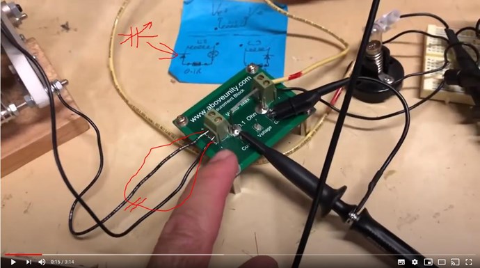
If the pix below is what he is using to switch the primary, there is no path for the collapsing current to reach the power supply. What there is however, is a path for the avalanche current of the P-channel mosfet to draw current from the power supply! IOW, what he thinks is returned current is actually additional current draw from the supply. This is his circuit gain for OU IMO!
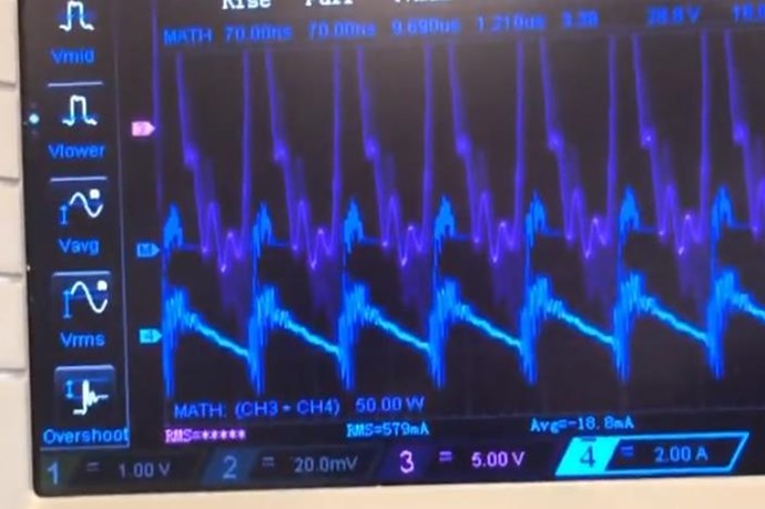
To confirm this, I need to study his schematic which he supplies on his forum somewhere but all I see on the driver pcb that CaptainLoz is using in video #9 is one, large case semiconductor.
This would explain why he states that when a load is presented on the POC, the returned current increases.
If this is how he and all his followers drive the primary of his POCs, there is no OU!
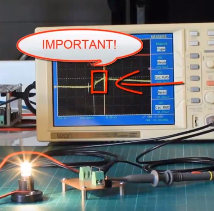
The second pix shows the scope waveforms from his schematic.
Regards,
Pm
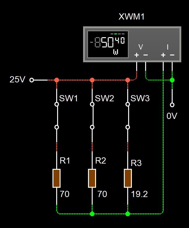
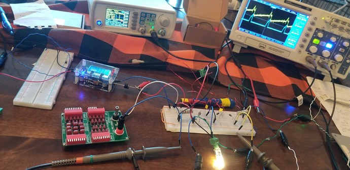
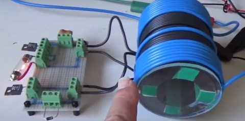
Ref: Captainloz Video 9 (showing COP = 2) replication
Completely Wrong
Now, I am sorry, but Partzman has everything completely wrong! I cant believe how wrong he has it! I mean really? WTF!!!
This bit here, it is truly words of a blind man:
This would explain why he states that when a load is presented on the POC, the returned current increases.
No wonder they are SO FAR BEHIND! They have no idea what so ever! More than 40 years in the game and this is where he is at, oh my! I mean, he cant tell the difference between a N Channel and a P Channel Semi:
avalanche current of the P-channel mosfet to draw current from the power supply!
It is more than obvious, WE USE N CHANNEL MOSFETS!
Let me give you all a very small reminder of what happens when this is right:
Partzman goes on to admit his mistake:
All,
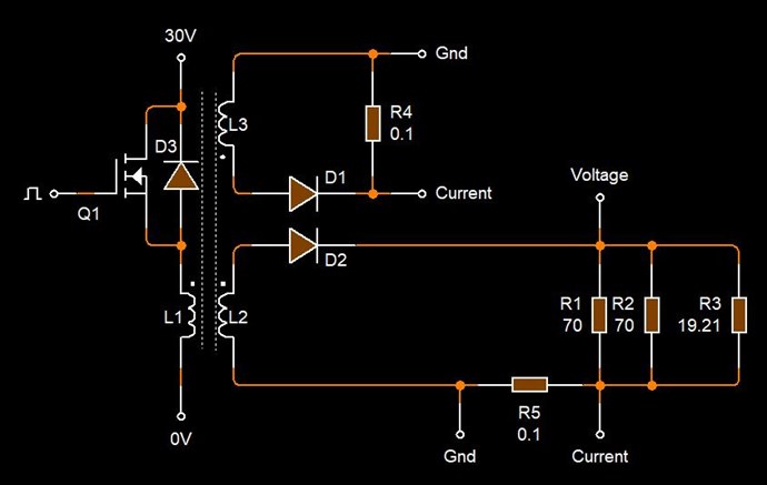
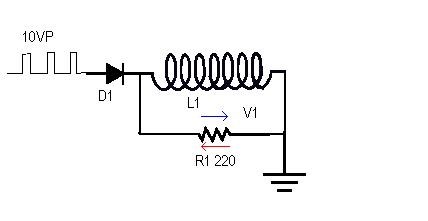
Since CaptLoz is not responding to Itsu, I will propose the input scheme I believe Chris is using for his device. I had stated earlier that there is no way for a single mosfet circuit to return energy to the power supply but that is not correct and I know better from past experience so, I'm blaming my 79 years young as the problem!
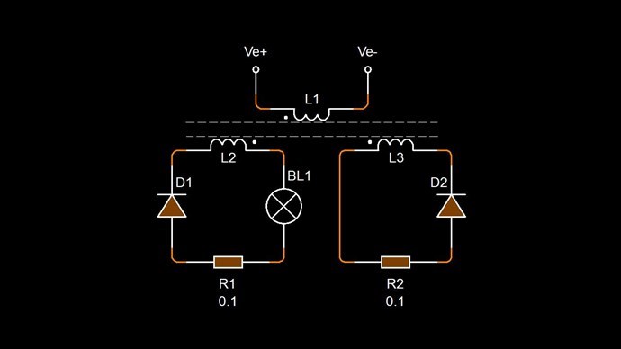
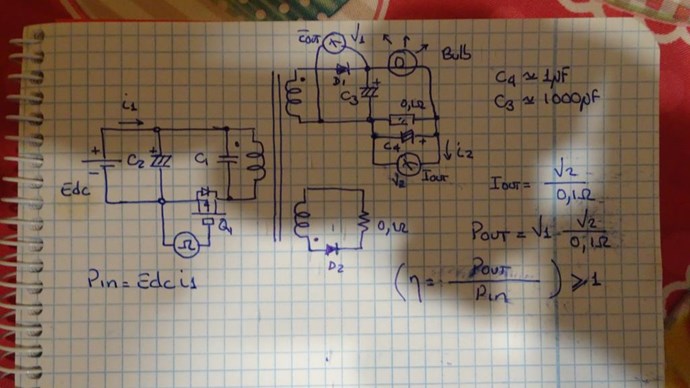
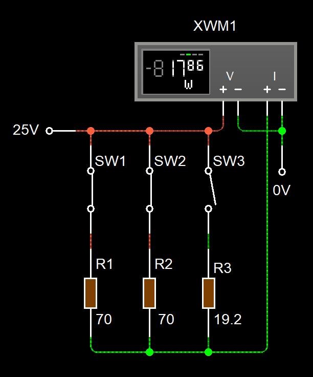
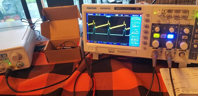
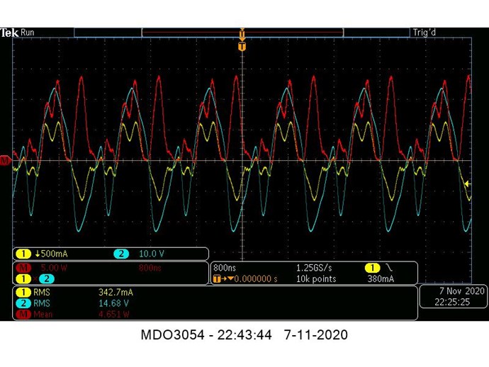
Anyway, I've attached a schematic and scope pix of the input circuit and will explain how it works. Ch1(yel) is the input pulse to the mosfet, CH2(blu) is the power supply voltage, CH3(pnk) is the output voltage across the drain, CH4(grn) is the current in L1, and Math(red) is the input power.
Initially, L1 is connected between + and ground via M1 and current begins to ramp up linearly. At a given point in time M1 is turned off and the current in L1 starts to fall as the voltage across L1 attempts to reverse. This action can not happen instantaneously however due to the capacitance that appears at the mosfet drain or Coss plus the parasitic capacitance of L1. So, this total capacitance will begin to charge and we will see a half sine wave at the output of the drain as long as the mosfet is not going into avalanche. When the voltage across the capacitance has reached a peak, the energy it contains will nearly equal the energy stored in L1 and the current in L1 will be zero.
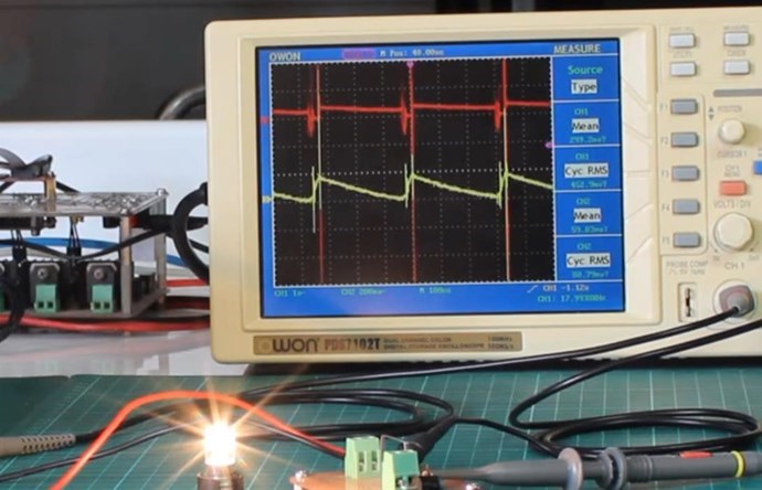
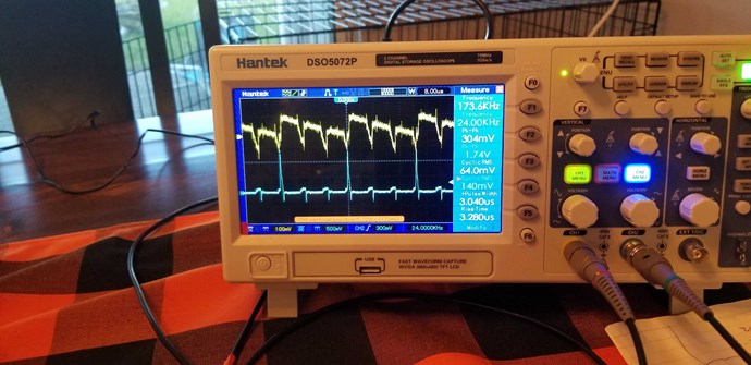
Now, the charged capacitance will use L1 for the discharge path back to the + power source and will discharge back to zero volts and the current in L1 will now be negative and nearly equal to the positive peak current reached during the charging phase. This is when the energy stored in C1 returns to the power supply as seen by the negative current and power on the scope traces. Notice the relatively low net average input power of 43.7mw when the average input power for just the positive half of the cycle is 747.7mw in the 2nd scope pix.
I personally did not use this type of input circuit when testing my variations of the POC device but will give it another try to see if there is any possible OU.
Regards,
Pm
Ref: Captainloz Video 9 (showing COP = 2) replication
Now, it would be nice to see: "Sorry everyone, Chris was right, and I did not pay enough attention".
Partzman, still does not have the full answer! He still misses the most important solution!
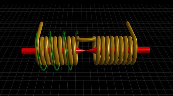
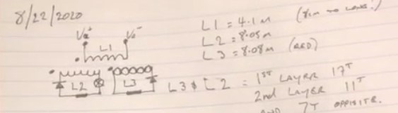
What is L1, your Input Coil, exposed to when it is Switched Off? Yes, that's right, Electromagnetic Induction via L2. Why are so many Experts so terrible when new things, they have not read in a book, been presented? WHY?
When others, use total non-sense, to try to explain, what they have no clue about, the Science community is in absolute turmoil!
Here is another post of absolute non-sense:
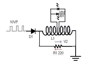
Chuckle~!  Yes, this is what I meant. The reason the output increases when that secondary is opened is that the leakage inductance created by the shorted secondary is gone.
If Chris is correct about the polarity connections on his POC circuit, consider the fact that the flux present in the core or air, can only change in magnitude over time due to di/dt but at no time is any additional flux or H field added to the circuit to provide a gain. Now if the secondaries only conduct during the "off" time of the primary, [IOW reverse the diode connections] there may be some magic in the collapsing primary driving the connected secondaries through the leakage inductances. This so called "leakage inductance" can store energy which few are aware off!
I know you are intent on replicating CaptainLoz's circuit and if he is still claiming OU at this point in time, it may be worth it. For my 2cents, I don't think he has OU.
Regards,
Pm
Ref: Captainloz Video 9 (showing COP = 2) replication
Completely Wrong
What did Don Smith tell us:
On the Magnetic side, you can make as many copies of it as you like
Making this claim: "but at no time is any additional flux or H field added to the circuit to provide a gain" exposes the total non-sense some people are exposed to, and push on others without having any factual evidence what so ever! What is clear, is Partzman is in total ignorance of Energy in the Magnetic Field and how Actions and Interactions occur in the Time Domain in Magnetics!
Assuming Electromagnetic Induction only occurs in One Direction is not only Foolish, it is outright Wrong!
It is clear, and presently obvious, to any logical mind: Greater than 90% of the Flux in the System is not anything to do with the Input Power, thus the Gain in Energy! Try explaining this to an Educated person! Good luck with that!
They currently, have 3 pages of nothing and it grows faster and faster, if they cant understand simple Science, and do not believe, why keep trying? Why do they persist? Is it because they know that its real, that they just do not understand it? How many independent replications, do they need?
What is clearly obvious, is Some People can not be helped! That is for absolute Sure!
Best wishes, stay safe and well My Friends,
Chris
P.S: I don't blame you at all for not responding to their questions Loz! Not at all! OMG!