Clemente Figuera

  • Topic Is Locked
  • 49K Views
  • Last Post 16 July 2019
Wistiti posted this 09 January 2018


Hi guys!

In the past I play a bit with the Figuera concept. It use the POC as we already know the potential. I think this guy, Marathonman, understand the principe behind the Figuera device...

Chris, if there already a tread about Clemente Figuera, feel free to move this at the good place!


Order By: Standard | Newest | Votes
Marathonman posted this 27 March 2019

creasyseecreasysee;    

That is the problem , it it NOT to zero at any time it is only to reduce to clear the secondary then back to full potential.

alfizik ;    

That style of winding has already shown to cause trouble. good luck though.

Regards,  

Marathonman 

Ourbobby posted this 27 March 2019

Hello,

          just a quicky to show you my winding. not that brilliant, it was very hard to wind. #15 wire is getting a bit stiff and winding it around a 8kg core takes some patience.

Regards

Ourbobby

  • Liked by
  • Cornboy
  • Chris
Marathonman posted this 27 March 2019

Reason # 2 of why i chose a C core for part G, it's way easier to wind.

Regards,

Marathonman

Ourbobby posted this 27 March 2019

Hello marathonman,

                                 where I live, it is not easy to get some items. I am always in awe of the ease that you can get many items so easily. just to get some ic's i have to wait weeks. to get a C section like you say I have not seen. also is it iron, ferrit or lamination? if i am to make a zillion of these things i must know. cos the energy company will want to buy them to stop them reaching the market. forget the muddering, they will be to busy chasing the delivery trucks and worried about the consta t bad pub licity. i live on a small island and any comings and goins are seen by everyone no secrets here


regards

Ourbobby

  • Liked by
  • Chris
Marathonman posted this 28 March 2019

I really hate to do this but my IGBT's just came in at 1.98 each, i think it took a whole 4 or 5 days to the house. powerhouses at 400 watts, absolutely could not pass it up and i have another 60 Coming from Arrow at 1.91.

as for the C core it is laminated M-4 grain oriented Silicon Steel from BridgePort Magnetic's custom made to my order.

being in America does have some minute advantages but the moment you get here you are a slave to the system.

below is my IGBT's

PS. my jig's are still not done. man getting some things free is just not worth it.

PSPS. i lived on Guam for 3 years, i love small islands.

Regards,

Marathonman

  • Liked by
  • Chris
Ourbobby posted this 28 March 2019

Ourbobby;

You would be correct in your original assumption of your core being to big. also you must be aware of the type of steel you are using it will have remnant magnetization which might be detrimental to the function of part G. just post findings along the way.

ps. welcome.


Just noticed this. comment! have to get my eyes tested. this is all i have to use. all i can hope for is that i can see it working. the steel is low carbon but with small amount of manganese. i think it was left over from a special job repairing a fishing boat drive shaft support. been in a shed for years. i should get some response so will keep at it.only when i know what i m doing will it work for me to get special core made like you have done. if is is tomuch then i can have it bored out and then rewind it

Thanks

Ourbobby

  • Liked by
  • Chris
Marathonman posted this 28 March 2019

only tests will tell, with it not being silicon steel you will have to have more winding's then say my core so it just might work out just keep all informed of your progress and any questions arise we will all be here to aide.

Regards,

Marathonman

  • Liked by
  • Chris
Marathonman posted this 29 March 2019

Wow i can't believe the company i work for screwed up my jigs some thing so simple. the slide plates are completely warped and both jigs are not at 90 degrees. plus the idiots has weld on the inside of the jig that stops the lamination from being flat against the plate wall after i stated many times to just tack it on the outside not full weld. not to mention weld splatter every where so i basically threw them in the trash.

so now i must pay for some jigs and definitely not from my company i work for.

Marathonman

  • Liked by
  • Vidura
Marathonman posted this 29 March 2019

Here is a very simple driver circuit i am working on. the driver is BS2101F-E2 at .86 cents each and only requires two small caps and a resistor. very simple but effective. the driver actually has a high and low side driver but the low is not used and tied to ground as per spec sheet. a simple cap can be put on the gate to ground to delay the transistor cutting of for a make before break scenario to mimic the brush two to three wire contact per Figuera part G..

Regards,

Marathonman

  • Liked by
  • Vidura
Vidura posted this 29 March 2019

Hey MM The driver has a good price. And the floating hiside channel is a good choice for the positive switching as well. Only it would not be advisable to connect a capacitor to the gate, as this would slow down the switching, which should be as sharp and fast as possible, more if a huge current is expected, to avoid excessive heating and losses. The make before break should be achieved at the signal stage, it could be by software, or another simple trick is to connect each signal source with small diodes to two or three contiguous driver inputs(these will turn on simultaneously) .The only expense is a good deal of additional small signal diodes and maybe a pull down resistor at each driver input. If the description is difficult to understand I can post a schematic if someone is interested. Regards Vidura.

Marathonman posted this 29 March 2019

 "as this would slow down the switching"

Really, we are only switching at 60 Hz so why in the world would we need fast sharp switching..... we don't in a make before break scenario.   the 100 nf cap would only delay the switch off by microseconds and that is all that is needed. i have a test board coming and i will test this out as i still think i am right. another thing is we are not sucking mega amps, we are only using maybe 1 or 2 amps at best.

we will see.

Regards,

Marathonman

  • Liked by
  • Vidura
Marathonman posted this 30 March 2019

Well i had a really shitty few days. where i live the scumbags stole my BBQ pit and chair from my front porch . now i come home and my epoxy double order was stolen off my porch. called manager and said stick it i am moving. 

IT'S THAT SIMPLE.

on a good note i was able to salvage my jigs after 15 minutes of beating with a hammer. i think i can use then if i can remove the inside weld and splatter. slide plates not shown will attach to the bottom and slide in grove with only up and back movement.

Regards,

Marathonman

Ourbobby posted this 30 March 2019

Hi marathonman.

                            I am gonna look for some silicon steel. I read your M4 grin oriented. is there a specil way this has to be when winding. I think grain orient is exactly that and has to be used like that to get the best result with special winding of coil.

Thanks

Ourbobby

Marathonman posted this 30 March 2019

A grain oriented core is just rolled to achieve most if not all the grain in the same direction which means it takes less potential to achieve the same magnetic results. so that means no there is no special winding needed,

why everyone has mistified part G is beyond me. sure part G has a multitude of actions happening at the same time but in the end it is just an Inductor with an active rotating brush.

Regards,

Marathonman

Ourbobby posted this 30 March 2019

Hi marathonman,

                            Thanks. I have reread 1908 and I think I get the comments by Buforn. will know betta when i get my test modle working.

@ chris.

Hi and thanks for the website. every time i log in and refresh my page i get taken back to the beginin. is there some way that we can stay at the spot

thanks 


Ourbobby

Marathonman posted this 30 March 2019

Really ! you should be listening to Figuera since Buforn was only a financial backer NOT a Professor of Physics.

i love your way of thinking...... rather comical actually.

I think the spot is called the newest button. Shazam  !

Regards,

Marathonman

Ourbobby posted this 31 March 2019

I aim to please! that is mi miself and i

i admit i have been confused a few times with the changes and upgrades to the figuera device. just when i and may be others start to assemble the projetct along comes a new version. so the problem becomes sticking with the old or scrapping that and going for new. wot say you? all will likeli work one better than the other.

  • Liked by
  • Vidura
  • Aetherholic
Marathonman posted this 31 March 2019

The ideas or recommendation you should be sticking to is the one that were brought up many, many times and not the ones either not prove or just an idea one came up with.

fore instance when i mentioned the inverse square law referring to the primaries being 2 to 1 to the secondaries this is can be replicated and proven by you and everyone else on the bench. when i mention the primaries should be the lowest ohms possible for the least amount of losses in this device is fact because part G controls the current flow NOT the primaries so why add more heat loss to the system when it is not needed.

another fact is part G has to be closed core to preserve the magnetic field raising it's efficiencies in the very high 90's is fact. in order to have  the same flux in an open core it would have to be quite large piece of iron to match that of a C or a Toroid and this to is fact.

the reason i went with the C core is the original replicator using a rotating brush had balancing issued from paralleled inductance on the non active side of part G so i and Eatherholic did some bench work and simulations and found out the C core has no paralleled inductance so i decided to go with the C style core. that and the fact that it is way easier to wind.

but with an open winding on the toroid like creasyseecreasysee did with electronic switching he has no paralleled inductance. one has to take into account that the brush when rotating was on the last winding over twice as long if not longer then that of the other winding's which cause an inductive roll off that gave the secondary the rounded sine wave peak to exactly mimic the sine wave of present day AC output so when using electronic for switching purposes your circuit has to account for these facts.

another fact is Figuera used multiple contacts at a time in a make before break scenario which also has to be incorporated in either electronic switching and mechanical switching.  the reason for this is for non sparking and a wider path for the secondary feed back to be easily injected into part G and a good separation of the north opposing fields in part G essentially making them two separate inductors on a one inductor circuit.

there are many other fact that have been stated on this thread that hopefully have not been deleted that should be accounted for in your design.

EDIT; PS. when using electronic switching with ones intention of using the AC output to a bridge rectifier for a DC output one can then use the fast type switching like creasyseecreasysee did which will give a saw tooth AC output to the bridge rectifier since it doesn't matter because you are transforming to DC anyways.

Regards,

Marathonman

Ourbobby posted this 31 March 2019

Hi marathonman,

                            thanks for being patient with me. creaseeasy links to the ferranti alternator which links to the ironless coils which links to figuera using ironless coils in everunity thread. oh wot a web of tangled weaving. ferranti is not figuera. there is a link but i dont see it yet. i dont see the zigzag coils without the required soft iron. unless the primary coil if only soft iron and output is the zigzag coil. this would put figuera strate in the middle of faradays homopolar machine. to much? yet i think there is something simple about this whole generater that is staring us in the eye and we are blinking to much. russel was clear, large disc on optic generater, periferal coils, modulater magnet drive. upside down similar to figuera

hopefully i might get some more delivery this week so i can start a build.

regards

Ourbobby


alohalaoha posted this 01 April 2019

Hey Marathonman

How do you do these days ? All ready for big Figuera finish ?

Tell me honestly does this diagram correct or not ? What do you think ?


Best wishes

Aloha


Marathonman posted this 02 April 2019

?????

For your information YES ! i am contrary to your belief.

If you don't have it by now you will never have it. 

plain and simple just like i told Hanon and many others. so much information has been presented you have to be broke upstairs not to get it by now.

Assuming your drawing represents electronics then yes if it represents the mechanical then no but then you knew this before you posted.

"All ready for big Figuera finish ? "

Slightly sarcastically said. i work 6 days a week and have little time to finish. a little mongrell stole my epoxy off my front porch so his parents know and will get refunded but until then i reordered thus sent to my job instead. also my jigs were badly constructed from work thus need fixing.

anything else you would like to know. ? what i would like to know are you building the Figuera device and have ANYTHING to add that has NOT already been posted.?

If you weren't being sarcastic then i apologize, i am bernt  out need break. 

Marathonman

alohalaoha posted this 03 April 2019

Hey Marathonman !

Good to hear you are OK !!

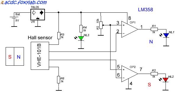
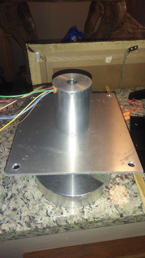
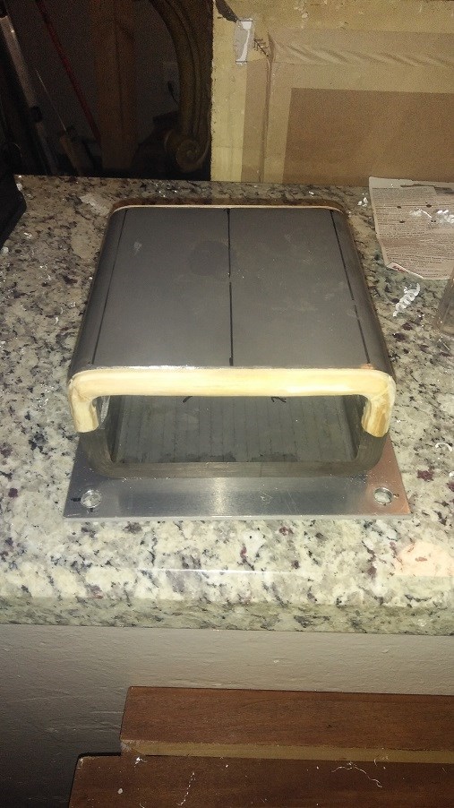
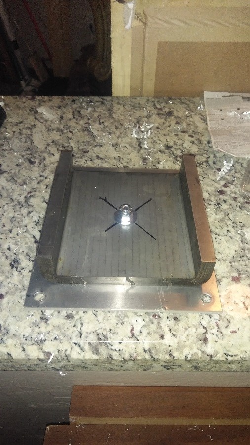
Yes, already presented diagram is a simplified electronic variant of Figuera BTG. It is 95% same as Floyd Sweet VTA device. Same principles rule here. And not only in Floyd device but in almost all working coil shortings configurations including old Tesla patent. I have no mechanical workshop to try build full mechanical variant of Figuera device like you and many good builders here had. So i am concentrating on electronic version. I am looking to find a way for G-part shorting/unshorting but not using ordinary bipolar, mosfets and igbt transistors.

Why?

1st i need as many transistors as have original Figuera G-part number of windings, 2nd, need very high power transistors which are not cheap, especialy SiC fets, and 3rd need very high speed switching off because output power of Figuera device is directgly related to switching (shorting/unshorting) speed, initial magnetic field in G-part core, wire lenght of shorting coil, magnetic field strenght of two primaries and cycling shorting frequency. Real source of power in Figuera device is not a device ownself but powerfull Aetheric wave due to compression and decompression cycle of two magnetic fields primaries. G-part act like compressed/decompressed Aetheric spring which directly excite Ateric realms and as result of such act we get directly injected Aetheric respoonse in a form of powerfull Aetheric wawe, which is pure energetic in essence, whatever we would call him: motional electric field, scalar field, torsion field, cohherent quantum field, longitudinal magnetic field or whatever else. That pure energy wave come form higher Aetheric dimmesnions, and it's direction is always perpendicular to it's exciters components like electric and magnetic field.

I have not anything to add, what was needed was already said in your topic and in the Chris forum.

As in Russia said: All "new" is long time forgotten "old". So generaly speaking we have not discovered a "bicycle". Many smart heads before us were had done this long time ago.

................

ps:I never make a jokes with a people having full working hands at job, whatever it is, especialy to those who has mount own heart, blood and tears in his creation, so i was not being sarcatist at all.

Best regards

Aloha

Marathonman posted this 04 April 2019

Many, Many thanks !. i am so tired i can't think straight. finally received my IGBT's..... ALL of them. at $1.95 average price for 405 WATT monsters i couldn't go wrong. my electronic test board will be in next week and also my reorder of epoxy came in safe and sound this time. pic bellow of the beasties !

will start assembling cores this week end and bobbins if i can hold my eyes open long enough.

Regards,

Marathonman

Ourbobby posted this 05 April 2019

Hi marathonman,

                            thats 90 igbts. I ordered the STGPL6NC60D as used in the digital circuit using the arduino. my 74ALS1032 arrived from germany today. the order was short so they are sending more. should be able to start next week bit by bit.

i have an idea based on the thought that figuera patent is red herring. it should be possible to invert the primary coils and part g. so part g would be a simple pulse drive. the primary coils are wound with the variable impedance similar to the part g that has toroid with pin connections for each coil input. the difference is pulse stepping is graduated across the now linearly increased windings wound coils. I might give this a go later.

ourbobby

  • Liked by
  • Chris
  • Vidura
Chris posted this 05 April 2019

Hey MM,

I think we could be a little less of a critique on others efforts?

A clear explanation with diagram's may help others end up at the same Goal? I believe all visiting this thread have the same common goal.

As a leader on this thread, it is your responsibility to be a leader, treat others with respect and guide them to the best of your ability.

Your last post really is not what I want to see on my forum, we have responsibility, we must lead the best we can, not abuse and criticise others.

Please re-visit your post and tone down the directed critique.

   Chris

  • Liked by
  • Wistiti
  • creasysee
Wistiti posted this 06 April 2019

Great reply my freind!!

  • Liked by
  • Chris
Marathonman posted this 09 April 2019

I will no longer post trying to convince or instruct people on the Figuera device. there is to many people that seam to be convinced their way is the highway even after my bench proven facts that are provable and replicatable. i will only post my build status and nothing more. ask a certain question in a pm and i will answer otherwise i will not respond to a question in the forum. i am through with uneducated or rather non thread readers that think the Figuera device is what ever their mind wishes to be at that moment in time.

good luck is all i may render, you will need it and then some.

Regards,

Marathonman

Chris posted this 09 April 2019

MM,

There is a right and a wrong way to treat people. The post you deleted, was abusive. Guidance does not need to be abusive.

If you want to help others, then great, but I don't want to see abuse of Members here on my forum.

Its entirely up to you if you want to continue to guide others that wish for your guidance.

   Chris

creasysee posted this 09 April 2019

Hi all!

Sorry, I don't have time for experiments and reports now, but I need to say a couple of things.

1) you need to know that I got a maximum of output when the keys overlap was approx 0.45. The attached image explains how it looks. When the overlap is zero, the output less in few times. When overlap is 0.5 or more the output decreases.

overlap

2) I tried to use a sine wave and you need to know that edge keys will be open longer than in the center, so they will get very hot and you need to use heat-sinks for them. I have broken keys already and you need to remember this.

Good luck and good figuering!

Regards, creasysee smile

alohalaoha posted this 09 April 2019

I will no longer post trying to convince or instruct people on the Figuera device. there is to many people that seam to be convinced their way is the highway even after my bench proven facts that are provable and replicatable. i will only post my build status and nothing more. ask a certain question in a pm and i will answer otherwise i will not respond to a question in the forum. i am through with uneducated or rather non thread readers that think the Figuera device is what ever their mind wishes to be at that moment in time.

good luck is all i may render, you will need it and then some.

Regards,

Marathonman,


Common Marathonman, take it easy man. You have our support and attention. Don't drop now till the finish line. Many people wait further instructions from you. Don't give up. This is my personal message to you. But do as you will. This is a MATRIX world and everything is possible, because it's virtual. Virtual like XP or WIN7 on your computer.

-------------

To all

This is very helpfull tool for Figuera buiders and many other researchers - Tiny Magnetic Poles indicator. Very usefull when expeimenting with coils.

From here:

https://acdc.foxylab.com/node/14

Hall sensor is from cheap computer cooler fan FS276 or VHE101B.

Pinout FS276 is same like VHE101B.

Pin1 = Vcc.

Pin2 = Collector of North Pole transistor - on sch. blue led.

Pin3 = Collector of South Pole transistor - on sch. red led.

Pin4 = Gnd.

That's all. Happy build.

Regards to all

Aloha

Marathonman posted this 10 April 2019

My conviction stands.

the next video is after my old camera died will be my part G in action with lights..

next is two triplets in action.

third is all triplets in action.

part G 10 aug square wire is here Friday will build Saturday night as i do work 6 days a week. video will be 100 volt 1 amp lights in action being swept 180 out.

Regards

Marathonman

Peter posted this 10 April 2019

Hi Marathonman, 

Although i do understand your frustration with some comments, i really hope you stick around.

There are a lot of people with their hearts on the right spot here. Never mind the trolls..

My build is coming along rather slowly.. and i will try to post some more pictures later.

Like said, hope you're still here when i am testing this baby, after all YOU'RE THE MAN    


Kind regards, 

Peter


Marathonman posted this 11 April 2019

Again no one pays attention, Peter i never said i was leaving just tired of repeating myself over and over and over because of the lack of attention to presented information which seems to not be benched to verify.

below is the circuit i am working on for the high side driver.

10 Awg square wire came in so it looks like i will be winding my part G this weekend and assembling primary and secondary cores and just maybe some bobbins.

as you can see in the pic below i am not using the low side of the driver so it is taken to ground. i decided to add the timing adjustment cap on the high "in" signal to extend the on time of the circuit to mimic the make before break scenario of the mechanical rotating brush. the driver is a newly added from the manufacture at only 86 cents and can handle up to 600 volts which to me is one of the best offered today.

Edit; Table top drill press and vise came in today which is good as i will be able to precision grind/buff part G's winding's to total flatness. 3100 rpm will be good as the brush is at 3600 so that is as close as i can get for the money

Regards,

Marathonman

Marathonman posted this 15 April 2019

Didn't get a lot done today. assembled table top drill press and drilled aluminum plates for mounting of part G's core and of the motor mount to plates. can't believe i found the motor screws at the hardware store. glued half round on part G's core face and sanded, cut aluminum 3/8 " threaded rod to 1 foot lengths with washers and lock nuts.

My jigs were a total flop because of the weld that worked it's way into the inside of the jig. spent all day with Dremel tool trying to rid the weld to no avail. ruined every bit trying to grind it. Dremel sucks and is putting out crap on the market. i need to figure out how to remove the weld on the inside of the jig before i can assemble the lamination's.

Picked up more ecofy cloth for the bobbins as well as a ton of tools, clamps and such. the sanding disc i purchased is 8,000 rpm rated so that is good at 3100 rpm of the drill press.

Below is an 80 dollar table top drill press that worked well beyond my expectation and then some and some build progress.

Regards,

Marathonman

Ourbobby posted this 15 April 2019

Hello marathonman,

                                 I hope it was not my comments on inverting the coil structures that upset you. we are all guilty of looking at things which doesnt mean that they are right. progress is made by challenging set procedures. although you have probably nailed this one shut tight.

i have started my build based on creaseasy circuit. i found that the register shift have to be reordered. no big deal, i only looked when i was trying to solder to same pinout! all sorted, to easy. as i am using solid iron bar for my cores i have improvised the bobbin using bobbin from plumbers teflon tape, throw tape away, cut bobbin in half and join together with thin plastic sheet and electrical tape. my bar is 25mm dia and bobbin id 1 inch so nice and close.


will keep you up todate with my progress


ourbobby

Marathonman posted this 15 April 2019

I am using Decade counters for my electronic switching part G. would like to use up and down decade but don't have time to study the circuit needed.

an curious if that is your primary shown.? forewarned that using solid cores for the secondary induces eddy currents and Hysteresis but would be fine for the primaries. Figuera used solid cores for his build but back then pure iron was much more available then now a days and much cheaper.  my complete set of 16 primaries and 8 secondaries ran me around 750 which to me is ok since it is top notch material being grain oriented also.

I am sorry for the ruff comments. after many, many years of explaining this device it seams very few actually try to confirm what i have presented on the bench.  benching is the only way to verify which is what i have done. it only take a few small tests on a small scale to verify all information presented.

hopefully i will resolve my jig issues during the week so i can assemble my cores this weekend. i am rigging up a tension system for my part G wire and will have it wound by this weekend.

Regards,

Marathonman

Marathonman posted this 16 April 2019

This graph is totally self explanatory and SPEAKS " VOLUMES ! " to the Science and Physics community.


Regards,

Marathonman

  • Liked by
  • Peter
  • Vidura
Vasile posted this 17 April 2019

Hello,

Thanks for the visual explanation. I honestly understand more from a image/video than from writen words. I tryed to disect the bottom part of your drawing. I made drawings myself, I tested with an ossciloscope and a magnet to see exactly what is going on. I twisted in any way I could and what I get from it, is this:

There are two 90 degrees out of phase waveforms which act upon a central coil and induce in this central coil, two waveforms that are also at 90 degrees from each other (like the inducer ones). Now... from my knowledge, two 90 degrees out of phase waveforms acting toghether have NO INFLUENCE upon each other (it is like you depicted, two magnets with like poles, say North ones, facing one another, that move one in relation to the other, at the same time, speed and direction). More visualy take two magnets, north poles facing each other, and move them toghether from left to right. They will not affect one another because they are moving at the same time, speed and direction.

In the central coil you will get the same. Two waveforms moving at the same time, speed and direction, 90 degrees out of phase and so... they will not influence one another.

Now my question is, how should the energy amplification happen if the two waveforms do not interact with each other? I do not understand the mechanism. Hope you clear this up for me and maybe for others.

All the best,

Vasile

  • Liked by
  • Vidura
  • Chris
Marathonman posted this 17 April 2019

Vasile and others that are still confused.

Figuera used two opposing fields to compress the field lines to match that of a standard N & S generator high intensity field yet remain apart and not combine. what most people are failing to realize is that when the reducing electromagnet is reducing it is also being pushed by the increasing electromagnet. when the reducing electromagnet reduces across the secondary it creates an Electric field and at the same time the increasing electromagnet is increasing across the secondary,  it to is creating an electric field. even though the increasing electromagnet is shoving the reducing field out of the core it still created and electric field. both electric fields combine thus giving you an intensity of the square of the two fields.

is is a remnant electric field and does not disappear when it is pushed/reduced across the secondary. also when current begins to flow in the secondary and the load, a secondary field is formed according to the Lenz's Law which will oppose the change. it is this field that is pushed across the Electric field created by both electromagnets. this is how the primaries induce motion into the secondaries.

two opposing fields one increasing the other decreasing will cause their Electric fields to be in the same direction thus giving you an intensity of square of the two fields .

we are moving the massless, weightless field NOT a huge hunk of iron so the potential to move this massless, weightless field is substantially reduce from that of the massive spinning iron

Electric fields combine opposing magnetic fields do not..

Regards,

Marathonman

Ourbobby posted this 18 April 2019

Hi marathonman,

                            i am using anealed steel. that is decarbonised at the first phase 730 - 850ish degrees. so the iron comes out around 99.5% purity. i work on heat color as my thermocuple is broken. nice orange color. at the moment i can only get the iron bar. so this will have to do to get the generator up and runing. there is a question i wuld like to ask and it relates to the earth connection. do we need to be looking at earth currents?

heres a picture of my board build a work in progress few conections to do. just got to finish conections for drivin G. shuld be able to see it working with the leds and slower speed.


regards


ourbobby

  • Liked by
  • Chris
  • Vidura
Vasile posted this 18 April 2019

Actually they are not 90 degrees out, they are 180  degrees out. when one is rising the other is falling.

see graph below, one rising, one falling, never below half way and never to zero or induction will fail.

Regards,

Marathonman

Hello again,

I get it now. The reason I thought that the primary waveforms where 90 degrees out of phase was because I was judging them as being AC, when in reality they are DC because they remain on one side of the zero plane and never pass it. So you are right in saying they are 180 degrees out of phase. From my calculations, in the secondary, you will have two waveforms that overlap one another and are in phase with each other. Now... the interesting part is that the primary currents do not affect each other, (because as one increases the other one decreases, maintaing the Max and Min limits) but in the secondary, the two induced waveforms combine. This is in my opinion the most important thing, this is why the ''amplification'' happens. It is like having 2 men working to lift the same weight, each of them can lift only 1 pound, but combined instead of lifting 2 pounds they lift 4 pounds. Something like that. At least this is how I see it.

All the best,

Vasile


Ourbobby posted this 24 April 2019

Hello,

         update. bit of a disaster yesterday. was setting my arduino board for the run test when all hell broke loose. my leds became so bright then went out. I looked at the power supply and it was showing 27volts. how can this be. it had been set at 2amp 5 volts. it is a yihau 3010d. this tells me it all. i repaired it some time ago when one of the lm2904 blew up. now i have no current. also no circuit to be found. 


have ordered new 2560 board. frustrating. do i spend more time trying to fix this ps without cicuit or toss it. decisions, decisions. 


will be another 10 days or so until the new board arrives. luckily i ordered extra shift registers the ones on the test board will be toast.


ourbobby

  • Liked by
  • Chris
  • Vidura
Aetherholic posted this 24 April 2019

The one thing that is 100% certain is that part g built correctly using a brush, works perfectly and runs cold. The last experiment I did when trying to find the part g limits had 30A average current at 60VDC to the brush for 20 minutes. The measured power loss was 6W and the core and wire were cold. Of course the current and voltage coming out of part G was much higher as you would expect from a magnetic amplifier...........


Aetherholic - One truth, One field

Ourbobby posted this 28 April 2019

Just been experimenting with some coils, while waiting for my replacement 2560 board. Not saying anything! Primary Coils have 300 turns of .8mm wire. Secondary just some 1.2mm wire I had lying around. The photos

are 1) Test coils, 300 turns 0.8mm, 12v 2.5 amp. 2) N-S coil polarity. 3) N-N polarity.

1)

2)

3)


Regards

Ourbobby

  • Liked by
  • Chris
Vidura posted this 28 April 2019

Hi Ourbobby, In order to make the configuration with like poles working,the secondary has to bee much shorter, and completely covered by the winding , otherwise the tests will bring not conclusive results, as flux will leak before reaching the coil. Regards Vidura.

  • Liked by
  • Marathonman
Ourbobby posted this 28 April 2019

hi,

just getting the feel of the coils. this time I have used the small coil to simulate the power offset when the part g is running. so i have big coil small coil as primaries. big coil as secondary. interesting results, slightly different outputs. different to last tests. photo 1 is big coil small coil in series with secondary in between N-N polarity. photo 2 is N-S polarity. Photo 3 is quick set up for test.

1)


2)


3)


No conclusions, just interesting to see effects.

@ vidura. Hi, I'll cut a short piece of core tomorrow and rewind it. just mucking around to see what i get before i try serious winding!

regards


ourbobby

Ourbobby posted this 28 April 2019

Hi marathonman,

                             ok, while waiting for parts, all i have been doing is to look at the interaction of the coils for myself. something you would most likely do. all these pictures tell me is that the responses i get are dependent upon method of placement and polarity. is not this what you have been saying? it is when i actually get a complete generator system in place that the fun begins. i shall have to learn how to manage the power in, learn how to calculate the coil  inductance for optimum effect, try and calculate a linear approach to extrapolation of generator size for power output. many processes likely to take a lot of time. so why you disrespect my mucking about?


ourbobby

  • Liked by
  • Chris
  • Vidura
Chris posted this 29 April 2019

My Friends,

I am here if you need me, PM me...

Understanding comes from guidance, it is To Nurture:


Marathonman, I would like to ask you to please treat others with respect, please be more careful with statements, and nurture others understanding. People come to learn, no one I know responds well to statements that belittle or degrade their work or understandings.

All that come are here to learn, we have to be respectful when we share our knowledge, guide, be the leader you are with Philotimo.

I have a responsibility for ALL Members, I care and do not wish any tension at all, for those working hard to advance, achieve and move ahead.

I ask, please don't put me in a difficult position where I have to make hard choices. Lets all get on, and be best friends!

   Chris

  • Liked by
  • alfizik
  • Vidura
Ourbobby posted this 02 May 2019

Hi,

      I have the new arduino board. i have made several unsuccessful attempts to test my driver board. the program sketch compiles and appears to uplod. i only get a clock pulse. nothing else. the wiring appears correct. the creaseysee progrm loads but will not run. reviewing this across the arduino community it wold appear that the mega2560 board can arrive with bugs. i do not think that i have time to develop an interest in solving bugs. i shall look elsewhere to see if i can resolve the figueras generator.

thank you for you assistance


ourbobby

  • Liked by
  • Vidura
  • Chris
Vidura posted this 02 May 2019

Hi Ourbobby, I would suggest to try with a basic program like blinking led to test the board. Vidura.

  • Liked by
  • Chris

Topic Is Locked

We're Light Years Ahead!
Members Online:

No one online at the moment


What is a Scalar:

In physics, scalars are physical quantities that are unaffected by changes to a vector space basis. Scalars are often accompanied by units of measurement, as in "10 cm". Examples of scalar quantities are mass, distance, charge, volume, time, speed, and the magnitude of physical vectors in general.

You need to forget the Non-Sense that some spout with out knowing the actual Definition of the word Scalar! Some people talk absolute Bull Sh*t!

The pressure P in the formula P = pgh, pgh is a scalar that tells you the amount of this squashing force per unit area in a fluid.

A Scalar, having both direction and magnitude, can be anything! The Magnetic Field, a Charge moving, yet some Numb Nuts think it means Magic Science!

Message from God:

Hello my children. This is Yahweh, the one true Lord. You have found creation's secret. Now share it peacefully with the world.

Ref: Message from God written inside the Human Genome

God be in my head, and in my thinking.

God be in my eyes, and in my looking.

God be in my mouth, and in my speaking.

Oh, God be in my heart, and in my understanding.

Your Support:

More than anything else, your contributions to this forum are most important! We are trying to actively get all visitors involved, but we do only have a few main contributors, which are very much appreciated! If you would like to see more pages with more detailed experiments and answers, perhaps a contribution of another type maybe possible:

PayPal De-Platformed me!

They REFUSE to tell me why!

We now use Wise!

Donate
Use E-Mail: Chris at aboveunity.com

The content I am sharing is not only unique, but is changing the world as we know it! Please Support Us!

Thank You So Much!

Weeks High Earners:
The great Nikola Tesla:

Ere many generations pass, our machinery will be driven by a power obtainable at any point of the universe. This idea is not novel. Men have been led to it long ago by instinct or reason. It has been expressed in many ways, and in many places, in the history of old and new. We find it in the delightful myth of Antheus, who drives power from the earth; we find it among the subtle speculations of one of your splendid mathematicians, and in many hints and statements of thinkers of the present time. Throughout space there is energy. Is this energy static or kinetic? If static, our hopes are in vain; if kinetic - and this we know it is for certain - then it is a mere question of time when men will succeed in attaching their machinery to the very wheelwork of nature.

Experiments With Alternate Currents Of High Potential And High Frequency (February 1892).

Close