Clemente Figuera

  • Topic Is Locked
  • 49K Views
  • Last Post 16 July 2019
Wistiti posted this 09 January 2018


Hi guys!

In the past I play a bit with the Figuera concept. It use the POC as we already know the potential. I think this guy, Marathonman, understand the principe behind the Figuera device...

Chris, if there already a tread about Clemente Figuera, feel free to move this at the good place!


Order By: Standard | Newest | Votes
Cornboy posted this 01 March 2019

 Hey MM, you will need a slow setting epoxy to do that, and the best would be to clamp the lamination's between unbendable steel plates.

 The epoxy will dribble out everywhere, so have a good think about what you don't want to glue together, and how to get it apart the next day.

 Regards  Cornboy.  smile

  • Liked by
  • Chris
  • Marathonman
Aetherholic posted this 02 March 2019

Cornboy

I posted some waveforms earlier in the thread. I can tune the AC to DC ratio by gapping the core which changes the ratio of part G inductance to the inductance of the primaries. This was my solution to the tuning problem and allows me to experiment with different primary configurations. 93 turns gives me a total ac inductance of about 500mH when measured across the two outputs.

Aetherholic - One truth, One field

  • Liked by
  • Chris
  • Vidura
Cornboy posted this 02 March 2019

 Aetherholic, that's really interesting, what size gap do you use to do that?.

 regards  Cornboy.  smile

  • Liked by
  • Chris
Aetherholic posted this 02 March 2019

Cornboy

Because my core is in this format [ | ]  I can completely remove one side and still have a closed path so the gap size can vary between none and infinite. 

Marathonman should also be able to gap adjust his [ ] format core if needed.

Aetherholic - One truth, One field

alset posted this 02 March 2019

Hi Aetherholic,

Thanks for the info. Very interesting to see your part G inductance to be about 500 mH with 93 turns. Which is the inductance of one of your sets of electromagnets? Just to see the ratio of impedances in electromagnets and regulator.

The variable core gap in part G to regulate its inductance is genius!!. I was just thinking of changing the number of turns to tune this device.

Best wishes!

Thanks

  • Liked by
  • Chris
Marathonman posted this 02 March 2019

Cornboy;

  I plan on using a jig with a hole in the bottom so i can fit a C clamp through it. i will them put a metal plate in the jig then 161 laminations then another metal plate then clamp.

The golf club epoxy is 24 hour epoxy and should be fine. with the hole in the bottom of the jig i can punch it out if i have to. i think it will work.


All;

I plan on removing or adding windings to tune use the gap as a last resort. plus i can adjust my brushes for a wider current window if needed.

Regards,

Marathonman


  • Liked by
  • Chris
Cornboy posted this 02 March 2019

 Hi All, finished machining Comm 3, now on to brush holder and end caps.


 Regards  Cornboy.  smile

Marathonman posted this 03 March 2019

It turned our really nice Cornboy so now comes the core issue. what is your plan of attack on that.?

Great work.

Regards,

Marathonman

Cornboy posted this 03 March 2019

 Hey MM, i do have a toroid already wound, but i will still be testing my inductive resister pieces.

 My main concern at the moment is the electro magnets, copper coated welding rods are not viable for me, so looking into other ways.

 Have been thinking lot's about slitting small laminated toroids to use all fields produced by inducers, what do you guys think??.


 Regards  Cornboy.  smile

Marathonman posted this 03 March 2019

Cornboy:

  As you already know i dabbled at the thought as did UFOP but was committed to the straight core design so i went no further.

my only concern was the collision points no being equal as the inner part of the toroid has a much shorter magnetic path then does the outer therefore colliding much sooner.  the other concern is does the South field compress the field lines like that of the radiating north field. i never got to that fork in my research so i left it a lone  my immediate gut felling is no but then again the Figuera device is like no other.

edit; the magnetic field will have to travel farther on the outside thus be weaker on the outside vs the inside which has a shorter path thus more intense. ?

PS. those who are following the electronic switching of part G needs to realize the end contacts where the peak of the primaries are at their highest and lowest needs to be on two to three times as long to get the inductive roll off to exactly mimic the AC sine wave of present household utility delivery. not if you are to rectify then use it as a DC supply.

Regards,

Marathonman

Marathonman posted this 09 March 2019

OMG! dealing with Temple is like discussing Physics with 5 year olds. very unprofessional with total lack of fore knowledge . after two weeks of miserable correspondence i finally got a due date of the 20th. my part G C Core will be in next week.

if you have any other moronic supplier of lamination material please do it other than Temple.

Regards,

Marathonman

Marathonman posted this 10 March 2019

While i have some free time i am working on the cheapest timing and switching that can switch the Figuera part G in a make before break scenario with the ends switched on twice as long. i will order from Mouser and test the circuit before i post it on line.

I found some IGBT's  that are being discontinued so the price is really fantastic and a driver for .86 cents. i will either use an up/down decade counter or just a regular decade counter. the up/down will require and Arduino or something similar but the regular decade counter just  a signal generation of some type.

there can also be other ways to switch as with a PNP with the use of a 300 volt opto-isolator to isolate the two sections of high and low signal.

i will also be investigating the infusion of the secondary feed back with electronics also that can be switched from the same signal of the positive brush electronics but will start at the opposite side of part G's positive side and end on the opposite side.

IE... positive electronic switching starts from left to right and the secondary feed back from right to left to mimic the brush rotation.

Regards,

Marathonman

Marathonman posted this 12 March 2019

Finally some good news Bridgeport is shipping today and Temple is shipping tomorrow. finally i get some satisfaction.

you people have no idea how much i have suffered  from the fatal blow. i lost 5,000 worth of very valuable test equipment and cores that were to F-in expensive to realize . trust me when i say it is nice to live alone.

Regards,

Marathonman

  • Liked by
  • EmilP
  • Aetherholic
Marathonman posted this 15 March 2019

Please remember folks, the primaries are ONLY reduced to clear the secondary then back to full potential as the other primary is reduced. at NO time is the primaries reduced past 50% or to zero. if you do this induction will fail as the compression of field lines is or was not maintained thus induction will fail and the output will plummet to almost nothing.

we are using duel mono poles to compress the field lines to that of a standard generator then reducing one and increasing the other to induce motion into the secondary at the same time forming an intense electric field around the secondary. when current begins to flow a second Lenz Law field will form and this field is what is pushed across the electric field formed by the reducing and increasing primaries in coherency..

the field lines must be compressed and maintained at all times or YOUR OUTPUT WILL FAIL. if you are reducing down to far then you need to have less windings on the end of your part G.

Regards.

Marathonman

mabberflouth posted this 17 March 2019

Hi,

    i have bean lookin at this figuera generater for a while and this is the best place i have seen talking serius about it. im gonna build one of these and i hope i can help on the way.

i am new here and want to say hi to everyone on this generater. i hope i can get grate results.

ave a good day


mabberflouth


Marathonman posted this 18 March 2019

Welcome mabberflouth;

Yes there is a ton of information on this site and thread. i have pored my heart out on this device in hope to change this screwed up world we live in. please read the whole thread and realize the amazing possibilities of this device and if you have any questions please feel free to ask away.

my core of my part G is being delivered today along with my 7 triplets. wire should be here any day now so can commence my build.

Regards,

Marathonman

Marathonman posted this 18 March 2019

Well i took some pictures of my C core part G and the new primary and secondary lamination but in the middle of of the upload to my computer my camera took a nose dive and is not recognized by my computer. so that means i lost all my video i recorded last week. i will go to the pawn shop and buy another one then post a pic of my new C core controller part G.

Edit; Managed to get one more pic out of it before another nose dive. my new controller core.

How sweet it is to be loved by Tempel and Bridgeport. they did an outstanding job of the cores and very fast delivery after we got past the Bs sales guy.

Regards,

Marathonman

Chris posted this 18 March 2019

MM,

Try all the different USB Ports on your PC/Laptop and a new cable.

   Chris

Marathonman posted this 18 March 2019

Cable new Camera very old, tried that does same thing but managed to squeeze one more out before another nose dive. time for another pawn run. Ha, Ha, Ha !

Regards,

Marathonman

  • Liked by
  • Chris
  • Vidura
Marathonman posted this 18 March 2019

Weird, i just took the battery out and let set for a while then took another pic and it worked but i still lost over 30 minutes of video in the process.

Below is brush holder on top of my new C core.

wire is coming which is square for less precision grinding.

Regards,

Marathonman

Vasile posted this 19 March 2019

Nice core. Is it Silicon steel? Hope it works good for you.

All the best!


P.S.: Nice table also.


  • Liked by
  • Chris
Marathonman posted this 19 March 2019

Yes they are,  Silicon Iron grain oriented 29 gauge M6. 14 primaries 6" long and 7 secondaries 3" long both 2.25 wide.

part G core is grain oriented silicon iron 6" x 6" 1/2" thick.

Regards,

Marathonman

Ourbobby posted this 20 March 2019

Hello, 

 This is my first post here. I have been following Figueras around the forums for a couple of years. Follow the information! I am collecting components for a digital build. I have just  collected a toroid - or a piece of steel bar with a hole in it! The dimensions are diameter 180mm, inner diameter 88mm, height 58mm. Next move on this is to decarbonise it in my small kiln. Then wind a Part G+R. I am a little worried that I might have too much iron here. Well I'll suck it and see.

Regards

Ourbobby

Cornboy posted this 20 March 2019

 Welcome, Ourbobby, have seen you asking on other forums.

 My advice is to read right through this thread, it may seem repetitious, with a lot of stuff you have already read elsewere, but you will pick up lots of hints and advice along the way that may help.


 Regards  Cornboy.   smile 

alfizik posted this 20 March 2019

Hi guys!
I read this forum with great interest! Many thanks to Chris for ordering this resource!
I am very interested in the prospect of recreating the Figuero device.
Thank you Marathonman for the leading role and a lot of useful information and tips!
I will try to post a photo of what I have worked out lately.

Marathonman posted this 20 March 2019

Ourbobby;

You would be correct in your original assumption of your core being to big. also you must be aware of the type of steel you are using it will have remnant magnetization which might be detrimental to the function of part G. just post findings along the way.

ps. welcome.

alfizik;

Welcome and thank you very much for the kind words. your part G looks good but i am wondering why such small wire keeping in mind that part G becomes the power supply when the starting power is removed. the more resistance you have in this system the more losses occurred. remember part G controls the current NOT the primaries ohmage.

also it looks like you are going electronic switching correct me if i am wrong. if you are not then with a rotating part G,  that style of winding will not work. good choice on a core but as i have stated in the past from my findings and that of Aetherholic that part G has parallel inductance on the non active side causing balancing issues of the primaries with a torroid type core.

all; heed the words well as the primaries have to be bigger then the secondaries or the magnetic fields will be to week to maintain the proper field pressure.

again welcome the both of you to the best troll-less forum on the web.

PS. anyone heard from Aetherholic lately.?

Regards,

Marathonman


alfizik posted this 20 March 2019

It was a toroidal core from some domestic autotransformer, dimensions 95x55x30 mm. I forgot to make a photo. Bends for soldering will be soldered from the sides. The electronic part is ready for me. Management board and 16 keys on mosfet IRFP260. Write through a translator from Google. If something is not clear, ask. Maybe you have any tips, they will be interesting to me. Successes to all!

  • Liked by
  • Chris
  • Aetherholic
alfizik posted this 20 March 2019

Hi, Marathonman!
The wire that I wrapped the toroid has a diameter of 0.71 mm. Inductance coil 0,265 Henry. There is another core in stock, measuring 126x71x64 mm. And also there is a wire with a diameter of 1.63 mm. Due to lack of funds on the wire and other parts, while using it. Besides, manual winding of a toroid is a considerable time-consuming work, but I still get to wind the second toroid for the sake of experiment and experience. I do not need more power from this device, it is more important to achieve its efficiency with a self-locking device and at least 10 watts of free power. And then it will be clear where to go, and it will be much easier in the sense of availability of funds.

In the photo, the core, which I keep in stock for now. Its overall power is 400 watts.
I hope you understand my text, as I write through a translator. And I also read through the machine translator Google, understanding the meaning of complex technical texts is not very good. Road going by walking!)

Regards!

Cornboy posted this 20 March 2019

 Hi MM and all, MM when you say parallel inductance is a problem with a toroid, is it because of the close proximity of the winding's on the inner part of the core?  Or is something else the cause?.


 Regards  Cornboy.  smile

  • Liked by
  • Chris
Marathonman posted this 21 March 2019

Cornboy;

   I am referring to the continuous wind of the original replicator . each half essentially separate but together which caused a balancing issue. when you are on EF you were advised on this issue and for sure on this site. when a continuous  wind is used it causes paralelled inductance which causes balancing issues.

when a C core or others are used they are not prone to balancing issues.

Regards,

Marathonman

Aetherholic posted this 21 March 2019

Marathonman

I am still here although I got side tracked with other issues which has taken up more time than intended. I don't have any further progress to report yet other than I will be concentrating on the coil triplets and the magnetic and electrical field interactions as I am happy with the part G performance. As soon as I have some more data or progress I will post it.

Aetherholic - One truth, One field

Cornboy posted this 21 March 2019

 OK MM, got it, thanks.

 Cornboy. 

  • Liked by
  • Chris
alfizik posted this 21 March 2019

Hi, Marathonman!
Perhaps you misunderstand me. I'm not going to use the rotation of the virtual brush, but walking it clockwise and counterclockwise.  (exactly as creazysee)  All the best to you and write how are you doing.

  • Liked by
  • Vidura
  • Chris
Marathonman posted this 21 March 2019

alfizik;

Yes, i understood you, i just didn't know if you were going electronic or not. please remember that the secondary feed back is sent into part G also so how are you going to account for that after testing.?

it is great having so many builders around the world contributing to such a great cause. we are the future.

Regards,

Marathonman

alfizik posted this 21 March 2019

Marathonman !

Yes, I have been working only on the electronic version from the very beginning, because it is too difficult to work with mechanics in my conditions and in an era when it is easier to buy a whole processor than to machine a small little wheel on a machine.
In general terms, I imagine how the Figuera device should work. And I understand that the energy of the magnetic field is pumped back and forth with each flowing over it in a system of two solenoids, filling in the increasing winding section of part G, following the receding brush, and vice versa, returning to the solenoid when the brush runs to the end of winding. I translated all the posts of this thread and read. (True, the translation is not very good, the machine translator does not know slang and sometimes funny words are obtained, sometimes just incomprehensible phrases.) But complete understanding will come gradually as the device becomes practically implemented, in steps, in steps. And then a great hope for you and Aetherholic.
Until I got acquainted with this forum, I did not know that part of G is not a chain of resistors at all. And last year I spent several months on these resistor circuits in several versions.
I fully share your views on this world. We need to rid it of oil and gas stink and other dirt.

Successes to all of us!

P.S. on photo one new solenoid in work. 

Marathonman posted this 22 March 2019

Quote; " Until I got acquainted with this forum, I did not know that part of G is not a chain of resistors at all. And last year I spent several months on these resistor circuits in several versions."

This my new friend is not good. most people had their own opinions and were miss lead by the patent when in fact it stated for understanding ONLY for the comprehension  of the device operation and "R" drawn in it's elementary manor to facilitate the comprehension of the device.  i for one am glad you listened to the wisdom of this thread and my open sharing of what i have learned.

My humble apologies for taking so long to get where i am at. i feel like i let everyone down, to much evil in this world.

Regards,

Marathonman

  • Liked by
  • Vidura
  • Chris
alfizik posted this 22 March 2019

Hello marathonman
Need urgent advice. And also all who read my post, write the answer. Does the direction of the winding of the solenoids relative to each other matter? That is, I have two solenoids, right and left. One wound, before winding the second asked this question. Which way to wind, clockwise or counterclockwise. 

Thank you! All the best!

  • Liked by
  • Vidura
  • Chris
Vidura posted this 22 March 2019

Hi alfizik, The most important thing is that the facing magnetic poles are equal polarity. In order to avoid inaccuracies of balancing it might be better to make all the coils equal in the same winding directions. Regards Vidura

  • Liked by
  • alfizik
  • Chris
alfizik posted this 22 March 2019

Thank you, Vidura! I'll start making the second solenoid right now. It is now noon.
There is another question: is the polarity of the power source of an electromechanical (classical) device variant important? Maybe someone from those who assembled the classic version, tried to change the power polarity of the entire system?
Everyone - thank you for being there!

  • Liked by
  • Chris
Marathonman posted this 22 March 2019

That is correct, each primary electromagnet needs to be exact copies of each other avoiding inconsistencies in magnetic field intensities. when making bobbins they should all be exact copies of each other also and by using bobbins it leave room for adjustments that are a vital part in tuning this device.

not sure what you mean by that last question. Ben Franklin thought current flowed from positive to negative and had a 50/50 chance of being right. unfortunately he got it wrong. current flows from negative to positive but the present system remains in place. negative is charging into counter space South pole and positive is discharging into space North pole. north is positive pressure and south is negative pressure. sounds a bit confusing at times..

when winding part G it needs to be wound as negative to the primaries and the brush positive causing two north opposing fields at the brush that keeps the two halves essentially separate. if i remember rightly it was counter clockwise from Set S to Set N.

Regards,

Marathonman


Marathonman posted this 23 March 2019

Picked up some really awesome IGBT's for an amazing price. these NGTB40N65IHTG's from Mouser are 400 watt beasts at a measly 1.96 each plus i found a high side driver for .86 cents each also at Mouser. i am just getting ready for when i do walk on the electronic side i will be ready. also designing a demo timing board with DipTrace to work out any bugs that may arise.

in the mean time my jigs for my cores are almost done at work so i will be assembling them soon using the jig and a C clamp to compress the lamination's along with my order for epoxy at 3300 psi with 3 hour work window and cure in 24.  i will be getting the bobbin material to construct them this week end.

here is a shot of my cores before epoxy. i just realized i had to pay for extra lamination because they only did in lots of a certain amount so i ended up with 16 Primaries and 8 secondaries.

Regards.

Marathonman

alset posted this 23 March 2019

Creasysee,

I have seen your site with your tests. Congratulations for your great work. Man, if you do not reduce that high impedance, 935 ohm, you are not going to get anything. You need more that 1000 volts to get a current of 1 Ampere. Also note that the coils are a low pass filter with time constant tau = L/R, that in your case is about 3/3 = 1sec. . You will need about five times that time , that is= 5 sec. , to see an increase in input signal to reach its max.output value. If your frequency is high then it has no time to reach it max. output before the input have been reduced again. Therefore your output magnetic field see little variation, and that is not good... Do you have an scope picture of your output voltage after the electromagnets? Check it.

Also note that the impedance Z is not calculated as you wrote as R + XL, but it must be calculated as:

Z = SQRT( R^2 + XL^2 )

Hope to help!

  • Liked by
  • Chris
  • Marathonman
Ourbobby posted this 25 March 2019

Hello,

Things are on the move. I have worked my toroid a bit to round the edges and wound tape around it . Ran out of blue so used my black tape to finished off, and mark out the start and end for the winding. Also, my arduino 2560 board arrived today.  i have some #15 wire, maybe just enough to do a complete wind with one join.

Am ploughing through this thread again! Cannot remember everything so am taking notes on what looks important!


Regards

Ourbobby


Ourbobby posted this 25 March 2019

Hello again,

                   I am reading through the early posts, and would have made a comment or two. Anyway, I still have a mental block with demonstrating how Figueras has demonstrated flux cutting. I get flux linking in an armature rotating through a magnetic field. But, for the life of me, I cannot visualise the difference here between cutting = Figueras and linking = today's technology. I am stuck with the concept of flux cutting being a physical movement - radial - through a magnetic field. NN or SS is suggested as flux cutting, but then we maintain a high flux density field without going completely through the field. The "y" field is static.

edit: With flux cutting, the rotational speed through the magnetic fields,when increased will give the massive outputs that the energy companies are afraid of!

Regards

Ourbobby


  • Liked by
  • Chris
Marathonman posted this 25 March 2019

Ourbobby;

  With a load connected to the secondary and after the primaries polarize the secondaries and current begins to flow an opposing field on the rising primary side of the secondary will form. this opposing field is what is swept from side to side. each rising primary will push this opposing field across the electric field formed by the primaries increase and decrease. with the sweeping action it induces motion into the secondary giving the illusion of motion to the electric field. this is flux cutting all day long.

so what that means is the primaries create the electric field then by the increase and decrease of the primaries it pushes the opposing field in the secondary across the electric field sweeping from side to side.

i hope you can understand what was just said.

Regards,

Marathonman

  • Liked by
  • Chris
creasysee posted this 25 March 2019

Hi alset!

You don't need to calculate, sorry. You need to measure.

Experiment #1: Measured U and I: Z = 50V / 0.28A = 178 Ohm.

Experiment #2: Measured U and I: Z = 50V / 0.39A = 128 Ohm.

Experiment #2 (lamps): Measured U and I: Z = 12V / 1.75A = 6.8 Ohm.

Experiment #3 (not published yet): Measured U and I: Z = 50V / 0.72A = 69.4 Ohm.


It looks like you have wrong calculations (Or I have wrong measurements, you can describe where I was wrong, don't hesitate, all people can make mistakes).


Regards, creasysee.  smile


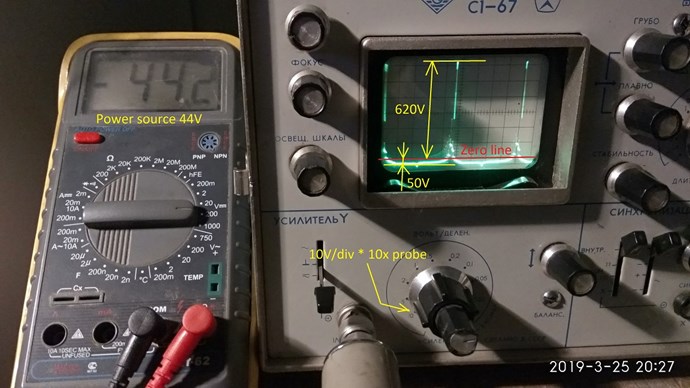
FYI: The current in primaries has DC part and doesn't cross the zero line. In the same time, the voltage on primaries exceeds source voltage in a few times (I have approx 200-400 volts, I will report later how much Measured: 670 volts) and crosses the zero line.

Voltage on primaries

FYI2: Sorry I don't know another formula for calculation impedance of inductance. Found it. Thanks. I'll fix it.

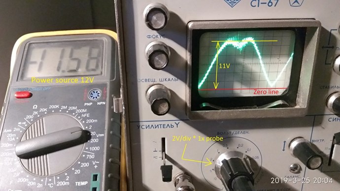
FYI3: Sorry, the voltage on the connected lamps instead of primaries is varying from 0 to 12V at 0.5Hz and at 50Hz (power source is 12V). Please note that the waveform has a defect on the upper side, this is due to pulsations from power DC source. I'm sorry, I have maintenance/enhancements of my device now.

Volage on lamps instead primaries

I understand you and I know what is T=L/R. But I'm so sorry, you need to build this and measure. Btw, the variac worked on the 50Hz grid fine (sure, I remember).

Creasysee, I have seen your site with your tests. Congratulations for your great work. Man, if you do not reduce that high impedance, 935 ohm, you are not going to get anything. You need more that 1000 volts to get a current of 1 Ampere. Also note that the coils are a low pass filter with time constant tau = L/R, that in your case is about 3/3 = 1sec. . You will need about five times that time , that is= 5 sec. , to see an increase in input signal to reach its max.output value. If your frequency is high then it has no time to reach it max. output before the input have been reduced again. Therefore your output magnetic field see little variation, and that is not good... Do you have an scope picture of your output voltage after the electromagnets? Check it. Also note that the impedance Z is not calculated as you wrote as R + XL, but it must be calculated as: Z = SQRT( R^2 + XL^2 ) Hope to help!

  • Liked by
  • Chris
  • Vidura
Marathonman posted this 25 March 2019

When the secondary loop back is in place the voltage throughout the system will increase well beyond 100 volts and here is why.

you have the the reducing primaries potential added to the reducing side of part G then at that moment the secondary feed back adds to those two potentials causing an substantial increase in voltage that forward biases the rising primaries. higher voltage will cause higher amperage to flow giving the rising primaries an added kick at the peak to replace the field line pressure of the reducing primaries. it adds the reducing primaries reduced pressure to the rising side allowing it to maintain the required output you so desired.

everyone will experience this rise in voltage so don't freak out when you test as this is a norm for this device.

Regards,

Marathonman

Marathonman posted this 26 March 2019

creasysee;

  Is that wave form actually from your power supply or from your secondary output.?

Regards,

Marathonman

  • Liked by
  • Chris
creasysee posted this 26 March 2019

@Marathonman

Sure, it's from the power supply.

The oscillogram without primaries and secondary, it's from lamps (active load) connected instead primaries. I wanted to show that a toroid's coil can produce full variation of voltage from zero to voltage of the power source, although the toroid has inductance 3H.

I'll provide an oscillogram for different frequency, for example 400 Hz, and we'll see it more clear. Now the frequency is 50 Hz.

Regards, creasysee.  smile

alfizik posted this 26 March 2019

Greetings to all researchers!
Long or short, but finally wound up two coils for solenoids.
Wound the method of Tesla bifilar. The second coil was wound by two wires at once, and this turned out to be much more convenient and faster.
I will put two photos here.

  • Liked by
  • Chris

Topic Is Locked

We're Light Years Ahead!
Members Online:

No one online at the moment


What is a Scalar:

In physics, scalars are physical quantities that are unaffected by changes to a vector space basis. Scalars are often accompanied by units of measurement, as in "10 cm". Examples of scalar quantities are mass, distance, charge, volume, time, speed, and the magnitude of physical vectors in general.

You need to forget the Non-Sense that some spout with out knowing the actual Definition of the word Scalar! Some people talk absolute Bull Sh*t!

The pressure P in the formula P = pgh, pgh is a scalar that tells you the amount of this squashing force per unit area in a fluid.

A Scalar, having both direction and magnitude, can be anything! The Magnetic Field, a Charge moving, yet some Numb Nuts think it means Magic Science!

Message from God:

Hello my children. This is Yahweh, the one true Lord. You have found creation's secret. Now share it peacefully with the world.

Ref: Message from God written inside the Human Genome

God be in my head, and in my thinking.

God be in my eyes, and in my looking.

God be in my mouth, and in my speaking.

Oh, God be in my heart, and in my understanding.

Your Support:

More than anything else, your contributions to this forum are most important! We are trying to actively get all visitors involved, but we do only have a few main contributors, which are very much appreciated! If you would like to see more pages with more detailed experiments and answers, perhaps a contribution of another type maybe possible:

PayPal De-Platformed me!

They REFUSE to tell me why!

We now use Wise!

Donate
Use E-Mail: Chris at aboveunity.com

The content I am sharing is not only unique, but is changing the world as we know it! Please Support Us!

Thank You So Much!

Weeks High Earners:
The great Nikola Tesla:

Ere many generations pass, our machinery will be driven by a power obtainable at any point of the universe. This idea is not novel. Men have been led to it long ago by instinct or reason. It has been expressed in many ways, and in many places, in the history of old and new. We find it in the delightful myth of Antheus, who drives power from the earth; we find it among the subtle speculations of one of your splendid mathematicians, and in many hints and statements of thinkers of the present time. Throughout space there is energy. Is this energy static or kinetic? If static, our hopes are in vain; if kinetic - and this we know it is for certain - then it is a mere question of time when men will succeed in attaching their machinery to the very wheelwork of nature.

Experiments With Alternate Currents Of High Potential And High Frequency (February 1892).

Close