Clemente Figuera

  • Topic Is Locked
  • 49K Views
  • Last Post 16 July 2019
Wistiti posted this 09 January 2018


Hi guys!

In the past I play a bit with the Figuera concept. It use the POC as we already know the potential. I think this guy, Marathonman, understand the principe behind the Figuera device...

Chris, if there already a tread about Clemente Figuera, feel free to move this at the good place!


Order By: Standard | Newest | Votes
Marathonman posted this 13 February 2019

The two wave forms should be opposite of one another Corrnboy. when one is falling the other is rising being 180 from each other.

one at peak the other low.

Regards,

Marathonman

  • Liked by
  • Chris
creasysee posted this 13 February 2019

Hi Marathonman and all!

I'm presenting a solid state version of part G (SSPG)! This is amazing! It works!!!

How it was made:

https://photos.app.goo.gl/mw8DsWQT7kF1UKxP9

Special thanks to Marathonman.

Regards, creasysee. улыбка

Cornboy posted this 13 February 2019

 Thanks MM, i was sure that was the case, so i will troubleshoot what i have done, probably something really dumb and basic.

 Regards  Cornboy.  smile

Cornboy posted this 13 February 2019

 Wow Creasysee, that's great work. will look forward to seeing how it drives the inducers.

 Warm Regards  Cornboy.   smile

Marathonman posted this 14 February 2019

creasysee:

  How dare you even doubt me. ha, ha, ha, ha !

Congrats on the electronic part G and a wonderful build and attention to detail. you are most welcome my friend,  so many people doubted me for so long because they were totally stuck on stupid but along comes someone like your self that is open to new horizons just split the Figuera log in two thus making all the crap i took for sooooo long totally all worth it.

I do have to ask are you using PNP's or NPN's with drivers.?   my electronic design was with small NPN's switching big PNP's that can be driven by all sorts of things. but we all know i am with mechanical at this time.

isn't it amazing that inductance can control current flow. just switching the winding count within the time constant of the circuit causing a current reduction. this is the very reason i share with people, to share what i have learned in hope we can change this F up cesspoll we call living being constantly controlled by some greedy ass wipe. 

just a word to the wise, the end channels on both ends must be on longer than the one's in between them to get the inductive decay roll off to mimic the AC wave exactly.

PS. "R" does not exist, it is part G's magnetic resistance (Inductance) drawn in it's elementary form to facilitate the comprehension of the device. R is part G and part G is R,  they are one and the same, Inductance.

CONGRATULATIONS ON A JOB WELL DONE IN LEARNING AND BUILDING.!

Regards,

Marathonman

Marathonman posted this 14 February 2019

Cornboy;

  As i have said Figuera used a closed core part G. what this did was preserve the inductance and the feed back from the secondaries without depleting the magnetic field. 

your rods do not have enough self induction or rather inductive reactance to change the current flow other than warp the signal slightly. this is what i was referring to when i said what i said about your rod set up. please do not get upset just please take a good word of advice, the open core of each rod is depleting the very thing Figuera preserved.

Solution to the problem,  attach a second core to each one and join them together at the ends therefore circulating the flux in the core not losing it to free air.

Regards,

Marathonman

  • Liked by
  • Aetherholic
  • Chris
Vidura posted this 14 February 2019

Cornboy, You could try to make a closed path with your g coils using magnetic shunts, joining the end of each coil with the beginning of the next. For testing purposes common soft iron blocks should be ok . If you position the coils vertically in circle you can form a completely closed magnetic path that way. Better would be to use an laminated core from a big transformer or Variac, but as you have this coils you could make a try. Regards Vidura.

  • Liked by
  • Chris
  • Cornboy
creasysee posted this 14 February 2019

Hi guys!

I do have to ask are you using PNP's or NPN's with drivers.?   my electronic design was with small NPN's switching big PNP's that can be driven by all sorts of things. but we all know i am with mechanical at this time.

I'm using IGBT transistors STGPL6NC60D and TC4420 drivers.

Regards, creasysee.  smile

  • Liked by
  • Chris
  • Marathonman
alset posted this 14 February 2019

Congratulations Creasysee!!

Much easier and robust than a rotating brush at 3600 rpm. Much easier to use it in other systems with more or less turns. Definitely much easier to tune.

My guess is that using half of the mosfets will also work.

Congratulations!!

  • Liked by
  • Chris
Marathonman posted this 14 February 2019

creasysee;

  When you finish your prototype you know you have to use a more robust IGBT then the one you are using now for the final build like in the 300 plus watt range.  the one you have now is only 56 watt which is of course good for a prototype.

again congrat's !

Regards,

Marathonman

Cornboy posted this 14 February 2019

 Thanks for the advice MM and Vidura, i found what was creating the signals in unison, when i decided to stop the commutator with the power still going to the bulbs, and found i still had half wave signals in unison Huh?.

 I used 24v battery instead and have opposite signals.

 The power source i have been using is 240v mains through a new 1600v 150a bridge rectifier,shouldn't the DC signal coming out of this unit be a flat line?. I have limited electronic knowledge { as you probably have noticed }.

 Going by the signal now, i  have a commutator problem and will be working on that before going forward.

 Regards  Cornboy.  smile

 PS. MM no offense taken, all good, i know your heart is in the right place.

Marathonman posted this 15 February 2019

ALWAYS !  humanity comes first in my book. that is why i open source everything i know.

Thank you,

now lets build this sucker together and change humanity as we know it !   i will supply the coffee and donuts imported from Barcelona Spain of course....Figuera style.

Marathonman

Marathonman posted this 17 February 2019

Cornboy;

  No the signal coming from your Bridge rectifier will not be flat line and you need smoothing caps to fill the dip when the AC goes to zero crossing over to the negative side. i would suggest to study up on this subject a little and maybe find a good online tutorial about how much capacitance you need per your current draw. i found one last year and i will see if i bookmarked it, if i did i will get the link to you.

Regards,

Marathonman


Cornboy posted this 17 February 2019

 Thanks MM appreciate it.

 So can this type of power supply be used in this device?, if not what is the best way to supply 100 to 200 v pure DC ?.

 Regards  Cornboy.   smile

  • Liked by
  • Chris
  • Zanzal
Marathonman posted this 17 February 2019

Yes your set up will be just fine you just need smoothing caps. just for safe measures you might want to mount the bridge rectifier on a heat sink with a fan for good measures. using a variac will give you the advantage of any voltage you need and if it is connected to an isolation 1 to 1 transformer it will have added protection.

Regards,

Marathonman

  • Liked by
  • Chris
  • Zanzal
Cornboy posted this 17 February 2019

 OK MM, have done some reading and it looks like i need about 400v 200uf cap across bridge output.

 Also i happen to have a 3kva 1 to 1 isolation tranny on hand. The caps i will have to look through all my unpacked old Don Smith stuff, sure to have what i need there.

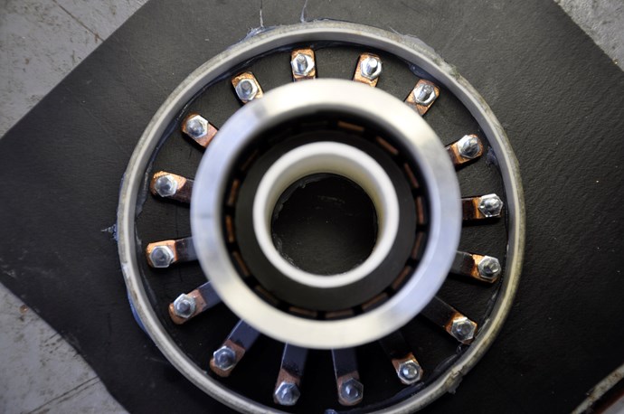
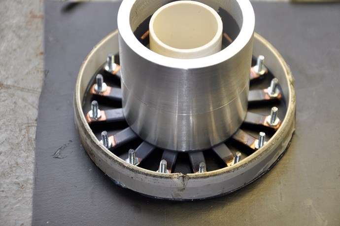
 The commutator is another story, the outside housing, being a pvc plumbing fitting, is too flexible, and prone to distortion

 Will make new smaller one with thick aluminum housing and comm bars embedded in resin, then machine the brush surface.

 I have some Garlic payments coming in shortly and am considering having parallel builds going, what i have now and a C core build. 

 Also on doing some research, i have found a company that makes toroidal shape Amorphous cores that can be custom built, even  into a thin walled tube, which i am thinking, back in Clemente's day, if he used a cylinder Gr it would most likely have been soft iron sewer pipe or similar.

 Thanks again for the help,  Cornboy.  smile 

Vidura posted this 17 February 2019

Hi Cornboy I was reviewing and found that in the newest scope shot there is an oscillation, it seems to be caused by interruption of the current flow, which shouldn't happen. In your commutator the brush should connect to two segments at least every moment to have a continuous current flow. maybe you should make the segments narrower and more quantity. Regards Vidura.

Marathonman posted this 17 February 2019

" if he used a cylinder Gr it would most likely have been soft iron sewer pipe or similar."

 NOT a chance, do you really think a professor of Physics would use sewer pipe that was special made in Germany......not hardly. more than likely it was made by Zeiss or rather Abby the one that first developed the controller for Zeiss's microscope. the time frame is just to close to be a coincident  and in Germany.  please remember it is drawn in it's completely basic form just for comprehension.

Vidura;

I agree, you can see the spikes and dips as it rotates. most certainly losing contact.


Regards,

Marathonman


  • Liked by
  • Zanzal
  • Chris
Cornboy posted this 17 February 2019

 Thanks Vidura and MM, yeh definatly loosing contact, will see if i can fix it, but a new design will be best.


 MM, back in those days, what would Ziess use for a G core cylinder?.

  • Liked by
  • Chris
Marathonman posted this 18 February 2019

 "MM, back in those days, what would Ziess use for a G core cylinder?."

It wasn't a cylinder it just rotated in a cylidrical fashion as the brush rotated and that is how he described it.

the original replicator used a toroid core and it worked but it was plagued by parallel inductance. Figuera was more than likely using an E I core with a fat center being close core with a roller brush as that is shown in the patent drawing. the roller brush was used rarely in those days only for specific things.

any type of closed core will do as you can see from Ceasee's video. as long as it is a closed core to preserve the magnetic field and the feed back from the secondary you will be all right. obviously a toroid is the most efficient with the least amount of flux loss then comes C core, then an E i core.

Open cores should be avoided at all cost as the flux losses are way to high and the core needs to be huge to compensate for the loss.

But by all means a cylinder could be used if you had the right core material. commutator bars are not needed because they were actually the windings making contact with the brush. in this case a roller brush would be excellent. but forewarned, you will experience parallel inductance wound like the original replicators repurposed Alternator core and fan assembly.

Regards,

Marathonman

  • Liked by
  • Chris
Marathonman posted this 18 February 2019

Just remember when building using electronics on top of part G that the peak of each primaries has to be on for twice as long as the one's in the middle to mimic the brush rotation exactly.  what this does is cause an inductive roll off that mimics the AC sine wave exactly like it should thus the secondary outputs AC  sine wave that can run anything you have.

so if using electronics either code that channel to be on for twice as long or wire it to be switched by two channels back to back that way you get the inductive roll off.  also remember you can add a cap to extend the on time slightly longer.

my Aluminum plates and brushes came in as well as ordering the cores from Temple Transformer as i will be talking to him tomorrow. Grainger has 3/8 inch aluminum threaded rod i will be purchasing for the plates to support my part G structure.

Regards,

Marathonman

  • Liked by
  • creasysee
  • Vidura
Cornboy posted this 19 February 2019

 Hi All,   MM what are you using to supply your build, for the start up?.

 Aetherholic, same question if you dont mind?. 

 The Variac i am using is getting way hot after just a few minutes running 24v dc.


 Warm Regards  Cornboy.  smile

  • Liked by
  • Chris
Chris posted this 19 February 2019

Hey Cornboy,

Maybe a Truck Battery? 24V at 600+ Amps for an hour+ may be enough?

   Chris

  • Liked by
  • Vidura
  • Cornboy
Cornboy posted this 19 February 2019

 Thanks Chris, the 24v is for testing the wave form coming from the commutator, through two opposite 24v bulbs.

 When i get that right, i will need at least 150 volts at small amps, to feed the primary inducers, to kickstart the device.

 A power supply that is adjustable would be ideal, but i think my Variac is either damaged or just too small.

 Best Regards  Cornboy.  smile

  • Liked by
  • Chris
Marathonman posted this 19 February 2019

No offence but please do NOT use a car battery set up a lone.   the amperage available will totally fry any and everything in it's path if you make a mistake. always use a high power ceramic resistor in it's path to limit it's amperage to a relative safe level of operation.  this precaution will not only save your devices but possibly your back side.

at 33 ohm 300 watt ceramic resistor with fan cooling will supply 3 amps  at 100 volts  or 24 volts at 8 ohms  which will not only supply your needs but save your supply from freaking out and shutting down or worse scorching everything you worked so hard for.

set your variac at 1.4 below your desired voltage desired plus caps after the bridge rectifier. ie  for 24 volts from variac set at 17 or 18 volts AC then rectify for 24 volts. peak is 1.4 the means square value then add caps for smoothing.

set veriac at 72 volts for rectified AC of 100 volts plus caps of course adjusted per your bridge rectifiers.

Think of safety first my Garlic down under friend.

Regards,

Marathonman

  • Liked by
  • Chris
  • creasysee
Chris posted this 19 February 2019

Hey MM,

A 10 amp fuse might be wise. But agree, no need to cook ones hard work, one has to be smart.

   Chris

Marathonman posted this 19 February 2019

100 volt  1 amp but capable of 5 amp.

the reason your Variac is heating up is because you are drawing more amperage then it is rated for.....meaning your part G is failing to control the current flow.

with out a closed core part G you will have to have a huge core to off set the flux losses associated with an open core.

My new C will be here in three weeks  as per Bridgeport Magnetic's.

Regards,

marathonman

  • Liked by
  • Chris
  • creasysee
creasysee posted this 19 February 2019

Hi all!

I spent a lot of time learning a "Delayed Lenz Effect" when started learning the Figuera device. At the first time, I thought a part G isn't required and I was sure that the device uses multiplication of magnetic fields which have a phase shifting in an iron core.
This effect is described here and when a frequency is 208Hz the half period has 22mm (0.86"). I don't draw any conclusions here, we just need to take this into account, to know that such effects exist and with certain sizes of coils can have a negative (or positive) impact on the operation of the device.

My first tests (over a year ago) are used transistors in A class mode, primaries, and a very narrow secondary. I tried to find a point on the iron core where magnetic fields produce maximum EMF.

Regards, creasysee smile

alohalaoha posted this 19 February 2019

Класс Creasysee ! Super !


  • Liked by
  • Chris
Marathonman posted this 20 February 2019

I somehow fail to see the connection to the Figuera device on this one. granted i do know about the phase shift which is at the limit of the magnetic field from the coil irregardless  of whether it has a core or not. if you notice the sensor is the exact thickness of the coil away from it which is the inverse square law at work. meaning the magnetic field will only project out the length of the coil it self thus any farther away it will be non detectable by the sensor.

when the field lines are compressed  between the opposing electromagnets there will be no phase shift of the magnetic fields but there is in the storing and releasing of potential into the magnetic field of the primaries and part G.

creasysee, i found a good hard rocker of a IGBT  https://www.mouser.com/ProductDetail/ON-Semiconductor-Fairchild/FGH60N60SMD?qs=sGAEpiMZZMv4z0HnGdrLjvJKrjQHCeGHVg2NGQEGVpI%3d

just about the biggest bang for your buck.

Regards,

Marathonman

  • Liked by
  • Chris
  • creasysee
creasysee posted this 20 February 2019

Thanks, Marathonman, but it's very expansive for me $5 vs $0.5. 

I have 600V 6A IGBT and 1kW variac as part G, so I don't see any reason to enter the power of more than 1 kW. First tests will use 48 IGBTs, each IGBT has 56W power dissipation and processing 1/48 part of the energy, so it will dissipate 1kW/48 = 21W even if each transistor will dissipate all power. So, I think it will work safely because transistors work in key mode (not active mode) and have fast drivers.

Really my part G has inductance 3H and XL = 2*Pi*f*L = 2*3.28*50*3 = 942Ohm, thus I can enter I = U/R = 300V/942 Ohm = 0.32A. (I cannot enter 600V, because it's inductance load, need a voltage margin). I chose the wrong variac...

Most likely, I will work at frequencies below 50 Hz, 16 Hz for example. We do not know at what frequency Figuera worked.

Good figuering!

Regards, creasysee smile

  • Liked by
  • Chris
Marathonman posted this 20 February 2019

I was going by the wattage not the 600 volts that after the derating it would be just fine at 100 to 150 volts and that was @ 3.72 each for a power house of an IGBT.

Barcelona was at 50 hz at the turn of the early century and forewarned, it is really not good for it to run at low speeds. it wears the brushes and the winding's out faster but of course your electronic so no brush wear.

Marathonman

  • Liked by
  • creasysee
  • Chris
Marathonman posted this 23 February 2019

I was just quoted price on some cores from Temple Transformer i just can't refuse..... omg i will be the proud owner of 14   2.25 " x 2.25" x 6 "  and 7  2.25" X 2.25' x 3 " in less than two weeks.

you guys can not believe how awesome i feel right now as i almost pissed on myself getting this news. sorry Chris i am just elated at this prospect  of getting back in the saddle again.

I was expecting  a royal rear end but lord knows it was a very sane proposition that i can jump on.

finally we shale prevail over the low down  trolls that oppose us and thank you to those who listen to reason not fantasy.

Hyiq will change the world as we know it.

Thank you Wistiti for recommending  a site i could share my knowledge freely.

Regards,

Marathonman

Chris posted this 23 February 2019

Yep, Trolls are Not Very Smart:


Almost 13 weeks and nearly 20,000 views, the globe is pretty red now! The Trolls still visit us, they just know they have Zero chance of staying alive here! It appears the entire Internet has waited for a safe secure place to plan their work flow!

The other forums are dead, all chatter is the same chatter they were messing around with 10 years ago! Old news for all here!

Go MM, keep up the good momentum! Many visit to see your progress! All others here also!

   Chris

Vidura posted this 23 February 2019

MM, I'm happy that you can resume your building.May I ask you if the cores are laminated silicon steel, if yes is it non orienteted or oriented grain cuality? @ creasysee I guess MM is correct in pointing to the current capabilities of the switches, as it is a magnetic device.Be aware that aetherholic burnt a 100A bridge rectifier with his partG. Another thing that should be considered is that the mechanical brush perform a coilshortening while moving over the part G, which we know having a great effect on inductance. To mimic this behaviour a bidirectional conducting switch (MOSFET)would be needed. A comparison between IGBT and MOSFET would be valuable for development of the solid state version of the device. Regards Vidura.

Marathonman posted this 23 February 2019

Vidura,


 That would be grain oriented M6 with the grain length wise and yes it is laminated. it is to expensive for solid pure iron cores for the primaries and also something that can be done by all replicators.

that is also correct on the brush coil shorting. by having the brush make contact on two or three winding's at a time it will eliminate spikes or current interuptions that are detrimental to this device. it is also a wider path to inject the secondary feed back into part G and a wider separation of the opposing magnetic fields of the inductor part G.

the whole reason i chose to do mechanical was not only can mechanical sustain a higher amperage but to gather all available information i can getting a complete understanding of the device parameters before moving forward with the electronic version. which i might add i have a very good understanding of this device already so the electronic version will be no problem.

there must be two to three channels on at a time to mimic the brush and for the end channels to remain on for twice as long as the ones in the middle to get the proper inductive roll off to exactly mimic the AC wave form.


Regards,

Marathonman


alset posted this 25 February 2019

Thanks, Marathonman, but it's very expansive for me $5 vs $0.5. 

I have 600V 6A IGBT and 1kW variac as part G, so I don't see any reason to enter the power of more than 1 kW. First tests will use 48 IGBTs, each IGBT has 56W power dissipation and processing 1/48 part of the energy, so it will dissipate 1kW/48 = 21W even if each transistor will dissipate all power. So, I think it will work safely because transistors work in key mode (not active mode) and have fast drivers.

Really my part G has inductance 3H and XL = 2*Pi*f*L = 2*3.28*50*3 = 942Ohm, thus I can enter I = U/R = 300V/942 Ohm = 0.32A. (I cannot enter 600V, because it's inductance load, need a voltage margin). I chose the wrong variac...

Most likely, I will work at frequencies below 50 Hz, 16 Hz for example. We do not know at what frequency Figuera worked.

Good figuering!

Regards, creasysee smile


Hi Creasysee,

940 ohms is huge!! I think you can tune your toroid by reducing the number of turns. A quick test is just to tap your L meter into the last contacts of your last mosfets instead than in the last turns of the toroid. If you are so kind please do it and tell us. Thanks.


If I remember fine Aetherholic did his part G with around 90 turns. Maybe he can confirme that value and maybe add his values of inductance and XL


As Marathonman said Figuera was trying to pour his production into the main network so probably he used 50 or 60 Hz.


Best wishes!!

creasysee posted this 25 February 2019

Hi all!

940 ohms is huge!! I think you can tune your toroid by reducing the number of turns. A quick test is just to tap your L meter into the last contacts of your last mosfets instead than in the last turns of the toroid. If you are so kind please do it and tell us. Thanks.

 Thanks, @alset!  I'll try when will start testing my triplets. I'm building it yet.

For all, review this again: the Ferranti-Thomson alternator. I plan to make the distance between primaries adjustable.

UPDATED: The inductance between the last contacts of my last IGBT is 0.3H. In the same time, full inductance has the same old value is 3H. It's strange, I tried to measure a few times (a load was disconnected). Maybe my L-meter is wrong.

  • Liked by
  • Chris
  • Vidura
Marathonman posted this 26 February 2019

If you were to tap the last mosfet to the left and the end that will give you the peak of set N  then disconnect the end leaving the tap at the last mosfet then connect to set S end and that will give you your lows. or you can tap just one loop and calculate from that your desired output.

940 is awfully high indeed, i am looking for 100 to 150 XL in my system ruffly. remember one needs not to go past the 50 % reduction mark or induction will be lost and the output will suffer drastically from the lack of magnetic field line compression. remember we are using two mono poles to compress the field lines to match that of a standard generator N and S high intensity field.

6.28 X 50 X .3 = 94.2 ohms  300 v divided by 94.2 = 3.185 amps peak primary.

Regards,

Marathonman

alset posted this 26 February 2019

I found this in another forum (EF , posted in february 2017). You should balance the impedance of your electromagnets and regulator in order to get a proper ratio of maximum and minimun current.


Ohms Law:

Voltage = Z_electromagnets · I_max

Voltage = (Z_regulator + Z_electromagnets)· I_min


If Z_regulator =     Z_electromagnets then I_max/I_min = 2

If Z_regulator = 2· Z_electromagnets then I_max/I_min = 3

If Z_regulator = 4· Z_electromagnets then I_max/I_min = 5


In some equations for inductance of a toroid, the inductance is proportional to the number of active turns squared , N^2   ( L_toroid ~ N^2 )


Hope to help! Electronics is the way to go!!

Marathonman posted this 26 February 2019

I understand what you are saying and yes it does make sense but implimenting that may be a problem as part G is a single layer 50 to 100 turn inductor and the primaries are 600 to 800 turn coil which will not be easy to attain matching impedance . maybe the way i am winding will be easier to match which is up and back,  4 in parallel with a total of 8 layers.

Cornboy;

Peter's vacuume cleaner approach seems  to fit your bill with a much sturdier housing.

Regards,

Marathonman

Vidura posted this 26 February 2019

When making measurements of the inductance on this devices you have to take in account the reduced impedance effect of the opposing magnetic fields, where the reluctance component becomes very small. Also the windings which are shorted by the brush on part G make a similar effect of reduced reactance. Although in the latter are many different types of interactions present so only experience will bring practical results on how to calculate impedance matching on this device. Regards Vidura.

Marathonman posted this 27 February 2019

The original replicator did mention that each half was to be calculated separately so your hypothesis has substantial merit.  when i build my next triplet i will investigate this.

Temple Transformer will not assemble my cores so i will have the arduous duty of assembling them myself which i have never done. well i will jump in with both feet because that is what we do.

I will have my cores in about two weeks primaries, secondaries and my C core part G.

Regards,

Marathonman

Cornboy posted this 28 February 2019

 HI all, some pics of Commutator Mach  3, and hopefully the last, on this line of experimenting.


First 2 getting ready to pour, last pic after pour and initial clean up in the lathe, now to finish machining the comm bars, etc.

 Best regards  Cornboy.  smile

Marathonman posted this 28 February 2019

Interesting Approach to a commutator. was the pour you are referring to just at the top or the whole inner area.

Marathonman

  • Liked by
  • Chris
Cornboy posted this 28 February 2019

Hi MM, i poured the bottom first, waited for it to harden, then poured from the top, to fill the whole body.

 The flat wire is 7mm x 3mm. now i will machine the middle out leaving a small amount of epoxy, and only machine a path in the copper wide enough for the brushes. The positive feed is a 7 x 3mm ring connected to the brass bolt.

 Regards  Cornboy.  smile

  • Liked by
  • Chris
Marathonman posted this 01 March 2019

Ah, now i get it. to many work hours as i am beginning to understand blond woman now. ha, ha, ha. i will be at 60 plus this week at 14 straight days. no rest for the determined.

Quote and shipping quote is back from Temple and tomorrow is is a green light on 7 -2.25" triplets that will be delivered to my job in two weeks plus Bridgeport will deliver at the same time frame as will S&W wire.

the sad part is i have to assemble my own core at 161 layers of .014  29 gauge so that means i will have to build two jigs, one for the primaries and one for the secondaries. i might use that golf club epoxy i had a while back then compress in a press of some sort.

any short cuts on the matter will be welcomed.

Regards,

Marathonman

  • Liked by
  • Chris
Cornboy posted this 01 March 2019

 Hey MM, one good method is to compress the strips hard and evenly, and then stitch weld with mig or tig, then epoxy them.

 I wouldn't trust just epoxy on compressed cores like that.

 Regards  Cornboy.  smile

  • Liked by
  • Chris
Cornboy posted this 01 March 2019

 @ Aetherholic, is it possible to post a scope shot of the wave form coming from your part G, that drives the inducers?

 Thanks in advance,  Cornboy.  smile

  • Liked by
  • Chris
Marathonman posted this 01 March 2019

Cornboy;

   I planed on putting a super thin layer of epoxy between the layers @ 161  the putting a block of metal over that then compressing it as far as i can, let dry for 24 hrs. then build my bobbins to mach which the core will be slid in. i would think 3,300 psi epoxy would keep it from breaking apart.  i do not have access to any type of welding machine unless i buy one at Lowes or Home Depot and that will by in the 300 range of added expense.

seems i might need to think on this more.

Edit; I am having core jigs made at work with 1/32 clearance so i can compress my cores without slippage.

Regards,

Marathonman

  • Liked by
  • Chris

Topic Is Locked

We're Light Years Ahead!
Members Online:
What is a Scalar:

In physics, scalars are physical quantities that are unaffected by changes to a vector space basis. Scalars are often accompanied by units of measurement, as in "10 cm". Examples of scalar quantities are mass, distance, charge, volume, time, speed, and the magnitude of physical vectors in general.

You need to forget the Non-Sense that some spout with out knowing the actual Definition of the word Scalar! Some people talk absolute Bull Sh*t!

The pressure P in the formula P = pgh, pgh is a scalar that tells you the amount of this squashing force per unit area in a fluid.

A Scalar, having both direction and magnitude, can be anything! The Magnetic Field, a Charge moving, yet some Numb Nuts think it means Magic Science!

Message from God:

Hello my children. This is Yahweh, the one true Lord. You have found creation's secret. Now share it peacefully with the world.

Ref: Message from God written inside the Human Genome

God be in my head, and in my thinking.

God be in my eyes, and in my looking.

God be in my mouth, and in my speaking.

Oh, God be in my heart, and in my understanding.

Your Support:

More than anything else, your contributions to this forum are most important! We are trying to actively get all visitors involved, but we do only have a few main contributors, which are very much appreciated! If you would like to see more pages with more detailed experiments and answers, perhaps a contribution of another type maybe possible:

PayPal De-Platformed me!

They REFUSE to tell me why!

We now use Wise!

Donate
Use E-Mail: Chris at aboveunity.com

The content I am sharing is not only unique, but is changing the world as we know it! Please Support Us!

Thank You So Much!

Weeks High Earners:
The great Nikola Tesla:

Ere many generations pass, our machinery will be driven by a power obtainable at any point of the universe. This idea is not novel. Men have been led to it long ago by instinct or reason. It has been expressed in many ways, and in many places, in the history of old and new. We find it in the delightful myth of Antheus, who drives power from the earth; we find it among the subtle speculations of one of your splendid mathematicians, and in many hints and statements of thinkers of the present time. Throughout space there is energy. Is this energy static or kinetic? If static, our hopes are in vain; if kinetic - and this we know it is for certain - then it is a mere question of time when men will succeed in attaching their machinery to the very wheelwork of nature.

Experiments With Alternate Currents Of High Potential And High Frequency (February 1892).

Close