Clemente Figuera

  • Topic Is Locked
  • 49K Views
  • Last Post 16 July 2019
Wistiti posted this 09 January 2018


Hi guys!

In the past I play a bit with the Figuera concept. It use the POC as we already know the potential. I think this guy, Marathonman, understand the principe behind the Figuera device...

Chris, if there already a tread about Clemente Figuera, feel free to move this at the good place!


Order By: Standard | Newest | Votes
Enjoykin2118 posted this 19 March 2018

Tell us the basic principle of figuera device IF YOU KNOW HOW. All great stuffs must be extraordinary simple.

i am 100% sure that without HZ(ED)-component there is no practical way to obtain C.O.P.>1.

The only way we can obtain it is partnered coils (or partnered magnets) configuration. i saw it in Floyd's VTA , in Figuerea Device and in many working and suppressd free energy devices.

Point of view is EXTREMELY simlpe. Suppress two opposite vector magnetic fields with proper timing and don't forget scattering phasing of coils and trigger HZ(ed) component which is self independent once properly triggered. HZ(ed) is obligatory responsible for generation of free energy because it is part of Aetheric forces. As Tesla said - there is no energy in matter, so the source is out of it, in Aether. HZ(ed) is portal to the Aether.

Why you always made big volume devices, why not start with small model ? The point is not in size but in idea.

p.s. what the hack is HZ(ed) ?

it is a STANDING WAVE, MAGNETIC STANDING WAVE!

This "came to hit now"! Behind a wave guide wall, there is quite concrete wavelength, and in same timinging, it is equal to infinity in a wave guide.By the way, at an entrance to a wave guide the plane wave turns by 90 degrees and with sidewise or precise - magnetic component, slip through it..

Regards

Enjoykin


  • Liked by
  • Augenblick
Enjoykin2118 posted this 19 March 2018

MM ok, I UNDERSTAND.

Good luck with Figuera.

Enjoykin

  • Liked by
  • Augenblick
Enjoykin2118 posted this 19 March 2018

Yeap.

Already done in attached file. But nobody listen and read.

By the way, yes!, we are still on the same suppressed (mirrored) side of reality.

ps.  What HZ(ed) did with ordinary radio - in case with HZ(ed) antenna ?

http://www.xferra.com

Regards

Enjoykin


  • Liked by
  • Augenblick
Zanzal posted this 05 April 2018

Good stuff Marathonman. You've inspired me to try one of these soon. I've got a couple ideas for approaches for a solid state part G. The most simple approach involves combing a constant current source with a sine wave along with an NPN and a PNP transistor to create two oscillating current limited DC sources that are 180 degrees out of phase. A simulation here:

Oscillating two phase DC source

The two opposing coil sets would go where the 1 ohm resistors are.

Should that approach fail to get good results I will likely try a 10-transistor Johnson Counter feeding a 10 tapped toroid approach, but not the one recommended by Patrick Kelly as that one appears (to me anyway) to have some flaws.

  • Liked by
  • Augenblick
EmilP posted this 16 April 2018

Dear Mr. Marathonman,

I read all the posts and have some suggestions:

1. Part G would be good to be totally independent of the rest of the configuration for better testing of variants, regardless of the configuration of the toroid, conductor coils, etc.

2. In the case of the final version, the brush can be used directly on the toroid, but on the inside of the toroid, to use the centrifugal force to press harder on the toroidal windings. (one problem is: copper is softer and will be rubbed).

I studied on a car distributor rotor that exactly what it does (send the spark to spark plugs) and is balanced for high speeds. The rotor contact is made in distributor cap and is made of a hard material.

https://i.ebayimg.com/images/g/mq8AAOSw8d5ZSPwR/s-l1600.jpg

Sorry for my english, I'm using Google Translate.

Yours,

Emil Platon

  • Liked by
  • Chris
  • Augenblick
Hopeful1 posted this 17 April 2018

marathonman

"Thank you" seems inadequate. What is missing from most forums is someone who is unselfish enough to share ALL their research and discoveries for the betterment of mankind. On this site there is none of that, only like minded people who want to see man progress.  I have had this patent saved for a lot of years and understood the basics of how it works, but thanks to your work i may someday be able to make it work. Thank you again.

Tony

EmilP posted this 28 April 2018

As an alternative to using brushes, you could replace with

heat treated copper, which has some spring to it.

I am with you in the effort to achieve the Figuera prototype.

Thank you for sharing your ideas and the progress of your work.


EmilP

  • Liked by
  • Chris
  • Augenblick
EmilP posted this 28 April 2018

Your brushes are the ideal case, I have just presented a simpler alternative to tests.

On rollers I saw a sparkle in a video.

I have the electricity on hydro (a small creek) that offers me 1.5kw with which I assure the house needs and hot water.

The heat is made with wood, and that's why I want to make the Figuera device, as time passes, I get older, and it will be hard for me to hang on to the stoves in the house.

I've done all sorts of home automation and I think I'll do it with you too.

Thank you again.

EmilP

  • Liked by
  • Chris
  • Augenblick
onepower posted this 28 April 2018

To brush or not to brush is the question?.

Given the choice I would rather change brushes every five years rather than change oil every 5000 Km and fill my gas tank twice a week. I would be happy to change those brushes knowing that power bill and that heating bill most pay was not coming in the mail. I would take care and patience changing those brushes making sure everything was just right because they represent my freedom and independence from a system bound to consume itself.

We should note there are no electronics to my knowledge which can handle a stray 50 Kv voltage spike yet a brush has no problem with it. Even a small carbon brush can handle a periodic 600 amp discharge which is not true of most electronics. In fact it is the most robust switch one can have in our toolbox.

Never underestimate the virtues of simplicity.

  • Liked by
  • Chris
  • Augenblick
Aetherholic posted this 03 May 2018

Marathonman, you are not alone!
Thank you for sharing such detailed information and I am sure inspiring many to try to build this device.
I am also in the middle of a build and I have a few observations to share.

Primary Coils
I decided to compare the different basic winding techniques for the primaries on a Gauss per Amp Turn basis. I used a static constant current supply to get a relative comparison. Gauss was measured at the same identical position on the edge of the core face (I am using a fast soft iron for the cores).

Magnet Wind
As the layers are paralleled up, i decided that the amp turns must be counted as if for one layer. On that basis i got 0.21 Gauss/AT.

Normal Wind - 0.51 Gauss/AT.

Tesla Wind - 0.73 Gauss/AT.

My Part G
I had made a 320 turns continuous wind of 1.9mm wire on a variac iron core torroid 240 o/d 115 i/d 80 high with top polished.
With closed wind, inductance at any two diametrically opposed windings is 1846uH at 100Hz.
Thus I think Part G behaves as a tripple inductor, one static across the two brushes and two dynamic from the north brush to the taps, the static inductor being increased as the torroidal flux builds.
I think this can only be achieved if the windings are closed which poses a question I would like to ask about your C core version, will it behave differently to the torroid version?
I will finish the Part G build in the next few days and then try to estimate its performance so i can finish the full complement of coils.


Aetherholic - One truth, One field

  • Liked by
  • Wistiti
  • Augenblick
Aetherholic posted this 04 May 2018

Marathonman,

This is the first time I have posted on any forum for the very reasons you stated. I also have got tired of reading replication information with only half the story. I feel its better to give full information even if the result doesn't work out, at least the reasons can then be fully investigated.

The coil tests I did were done at 2 amps constant current but were intended as a relative reference not absolute values to illustrate the effects of the different winds given identical coils and that the tesla wind does indeed give almost 50% more flux than a standard wind.

My part G coil was selected based upon getting the biggest coil I could get from any supplier who was prepared to do a full wind for me so for this build I have to live with whatever it will put out until I can model what part G is so that a full custom design can be done.

The word "static" that I used was to mean mechanically non variable to differentiate it from the dynamic inductances. Of course the inductance will change depending upon the field.

I have come to believe that Part G is in fact a genius replication of the coil triplets working in reverse with the static inductance being equivalent to the secondary coil and the dynamic inductances equivalent to the two primary coils but in this case the secondary is permanently energized and is used to power the primaries.

At the NN brush, there will be a south pole on either side, a south flux linking the two souths running through the core and a north torroidal field OUTSIDE the core but able to influence the windings. The SS brush will be the reverse. So we have a pure North and a pure South rotating in the core as you said  with an outside North and outside South rotating through the windings. (demonstrable by ferrocell and CRT viewing bucking fields). in other words, the same arrangement as two primaries and a secondary triplet BUT working in reverse with the secondary being permanently energized providing the field which is then modulated by the dynamic inductances. Pure Genius.

I will post pictures of the build.

Regards,

Aetherholic


Aetherholic - One truth, One field

Attached Files

  • Liked by
  • Chris
Aetherholic posted this 04 May 2018

For some reason I cant seem to post pictures other than as file attachments.

The attached picture in my previous post is Part G drive shaft with commutator, slip rings and floating drive for the brush plate.


Aetherholic - One truth, One field

EmilP posted this 04 May 2018

I have to tell you that it is an honor and a pleasure to participate in such a forum with quality people and professionals.

Neither I, like Aetherholic, have joined the forums until this year, although I have read thousands of posts over the past ten years.

Marathonman: You are not alone in the effort to make and learn others about the Figuera device, even if we do not post too much, we read regularly everything that appears here. Certainly a good many of those who read want and try to make the device, I'm sure of that. At each Figuera device created, the author will think about Marathonman ...

Thanks again, I never talked that much.

EmilP

Chris posted this 04 May 2018

@Aetherholic, EmilP,

Welcome!

All here are safe! We will not allow Trolls! We are in control here and Trolls will be Booted and reported as Trolls!

Marathonman is doing a great job of keeping the ball rolling with Clemente Figurea's Infinate Energy Machine and all posters are welcome.

Appologies MM, off topic, the floor is yours again my friend!

   Chris

  • Liked by
  • Marathonman
onepower posted this 04 May 2018

It would seem to me the process may be similar to a heat pump.

If we dissipate X electrical energy in a resistance we can expect to produce X heat energy as a result. However with a "heat-pump" we can dissipate the same X electrical energy and move up to six times more energy as heat from one place to another. In this case the external heat energy moved within a system would appear to be somewhat independent of the electrical energy dissipated.

Strange isn't it?... that energy is said to be conserved and I believe it is in the grand scheme of things yet here we have a common example where we can input X energy in one form and move six times more energy which happens to be in another form. It would seem to me that if a heat pump is not bound to a 1:1 energy equivalence ratio then perhaps we have been approaching this problem from the wrong angle.

One could say that we may have been taught the poorest way of doing things in our textbooks so far as the utilization of energy is concerned. 1X in 6X out... it's hard to argue it cannot work when it has been proven to work for decades. It's simply a matter of approaching the problem from the right angle with an open mind. 

  • Liked by
  • Chris
Aetherholic posted this 05 May 2018

Here goes with some more info and another pic.

This is my part G waiting final mechanical tweaking and wiring. Marathonman, yes I have holes through the slip rings for the commutator wiring. This build uses some 3D printed ABS parts so that I can adjust if needed. I am using a 4000rpm 24V DC motor with pwm controller at this stage. It takes 1.5A or less to turn the Part G and yes I have spun it up to 4000 without a problem, so I expect the 36 watts of loss to be inconsequential in this system.

The brush disc is 5mm Aluminium alloy. The brushes are 12X25 custom made with double wires as I have no idea yet what current can be produced. Theory is one thing, experiment is another as we all know.

This build was made fully adjustable so I don't expect it to last a long time, enough to be able to produce the full system. Then re design it based upon that experience.


Aetherholic - One truth, One field

Attached Files

EmilP posted this 06 May 2018

Congratulations on professional and aesthetic construction at the same time.
I have a question: does the brush disc, that aluminum alloy also provide electromagnetic shielding? The variable magnetic field generated by the strong toroid could affect the rest of the mechanisms and the DC motor?
I was thinking of using a hard plastic disk used for sanding, which also has the connection side.
The three modules (Switching, Variable Induction and Coil Block) of the Figuera device, in my opinion, must be as insulated as possible so as not to interfere with each other.
EmilP

  • Liked by
  • Chris
Aetherholic posted this 06 May 2018

EmilP,

I kept the motor as far away as possible from the torroid for that reason. The drive shaft is 316L stainless steel, non magnetic but is also relatively soft so you have to be careful not to stress it too much (I always make two of everything just in case). The disc is supposed to be non magnetic but as we know aluminium will levitate in a strong moving magnetic field. If this does happen I will remake it using stainless steel. All the screws and threaded rods are also stainless steel.

I think your idea to use a plastic disc is also ok except that you might need to use a spring to give enough brush pressure, I am currently relying on the weight of the aluminium but I also have space for a spring.

Aetherholic


Aetherholic - One truth, One field

  • Liked by
  • Marathonman
Aetherholic posted this 06 May 2018

Marathonman,

I hope our efforts will encourage more to join in. In these days of laser cut acrylic, lasercut and cnc metalwork and 3D printing together with CAD it makes it less difficult to be able to build devices like this.

For my bobbins i use acrylic tube cut to over length by the supplier then I use the big flat face of a standard grinder to get the length within 0.2mm which is needed because I use a winding machine. The ends are laser cut acrylic and glued using acetone which after a few hours is very strong.

I am looking forward to seeing your C core in action with the square wire wind, something I would need a few beers and some Dutch courage to attempt.

Aetherholic


Aetherholic - One truth, One field

  • Liked by
  • Marathonman
Enjoykin2118 posted this 07 May 2018

What would be if he used such a big toroid for Tesla Scalar Transformer ?

Tesla's Scalar Coil in action.rar {45Wt in, 2,19kWt out}

https://uploadfiles.io/jpv3v

Best regards

Enjoykin2118


Aetherholic posted this 08 May 2018

Now the comic interlude is over back to the main sub plot, getting to a working part G. The large brushes had too much bounce so I spent 16 hours redesigning some brush holders for the smaller brushes, 3D printing them, assembling and testing. Looks like they are good. The problem was spring tension, the best seems to be the coiled strip type which provides a more even pressure. Sounds like a jet turbine at full speed, looks like a Tesla scalar coil and functions as a part G. When static it makes a good coffee morning conversation piece. A variety of functions according to the beholder. I am posting from my phone at the moment so no pos, will post some more tomorrow. Maybe I will ad coffee grinder function also.

Aetherholic - One truth, One field

  • Liked by
  • Chris
Aetherholic posted this 08 May 2018

Seriously, the challenge of rotating brushes at 32m/s on top of a torroidal core and maintaining uninterrupted contact is huge. That's why it took Zeiss to make Figuera's part G.

Aetherholic - One truth, One field

  • Liked by
  • Chris
Aetherholic posted this 08 May 2018

And why he used a wheel brush.

Aetherholic - One truth, One field

  • Liked by
  • Chris
Aetherholic posted this 09 May 2018

Marathonman

My brush velocity at 210mm brush center diameter is 32.98m/s. This is the disadvantage of the torroid unless you do what figuera did. Your C Core has a huge advantage as brush velocity is much lower due to the smaller diameter and the adjustability.

Brushes seem to be a whole art in themselves with numerous materials, some as low as 17m/s up to 40m/s max velocity and numerous different wear factors and resistances so its important for anyone wishing to build this device to study the brushes also and the brush holders and the springs.


Aetherholic - One truth, One field

  • Liked by
  • Chris
Aetherholic posted this 09 May 2018

Another point to do with brushes and springs. As the centrifugal force on the brush increases it is possible for the brush friction to overcome the spring in which case it will stick in the holder. The only real solution for this is to have a lever mechanism with a weight to increase the brush pressure according to speed. Figuera's inner brush wheel must have acted in this way naturally.

I have experienced this phenomenon with the commercial brush holders I am using.

Aetherholic - One truth, One field

  • Liked by
  • Chris
Aetherholic posted this 10 May 2018

Resolution of the brush lift problem.

I added a lever and weight to press on top of the spring.

I had to counteract 84N of force so an M6 screw and 2 nuts worked out nicely.

Aetherholic - One truth, One field

  • Liked by
  • Chris
EmilP posted this 10 May 2018

Aetherholic;

Congratulations, I knew you could find a solution.
It's normal to be able to adjust the spring pressure on the brushes.
I'm with you, it's very exciting this building you do.

EmilP

  • Liked by
  • Chris
Aetherholic posted this 12 May 2018

Some more progress information.

Here is a not too good quality scope pic of the part G outputs N and S at low speed (yellow and blue).

So here is confirmation of the dual sine waves.

I can also confirm that there is huge energy stored in part G as if the brushes lift there is a very big negative spike despite running with magnet wound coils so the inductive collapse is mostly the energy in the torroid.

Aetherholic - One truth, One field

Aetherholic posted this 12 May 2018

An experiment on the coil triplet setup for those who have not done it yet.

Setup: two channel signal generator, channels phase locked 180 degrees out of phase, DC offset with 700mV 50Hz sine wave. Each channel connected directly to the gate of an IRF450 mosfet driving a magnet wound coil on the low side. High sides of both coils connected to DC. Both drive coils either side of an output coil as Figuera. The output coil with a load of 5 Ohms.

First test: coils in attraction mode

Second Test: coils in N-N repulsion mode

In both scope shots blue and yellow are the drive coils measured at the low side, red is the output coil.

Ignore the measurement numbers, look at the traces.

I think this proves the validity of the bucking arrangement in the figuera device.

Also, when testing the output coil windings with a magnet the entire winding length is north confirming that the north is being pushed out of the core.


Aetherholic - One truth, One field

Chris posted this 12 May 2018

Aetherholic, Marathonman,

You lead the world on the Figurea device! Bucking Coils has already changed the world, more are waking to this everyday!

Aetherholic, as you said, initially the measurements are not important, what is important is the Effects! Why? Because one can learn more from the effects than anything else!

It is very easy to improve the effects further, once learnt from!

Well done, great work!

   Chris

Chris posted this 12 May 2018

Good news, my C core is on it's way as of yesterday.


Chris, the PM function is blocked. tried a few minutes ago and all that happens is the log in screen and that is it, even after i am already logged in.


Hey MM, great news!

Re the PM, can you please clear your browser cache, it is working, I have tested, could be a cache problem.

:Let me know how you go.

   Chris

Jagau posted this 15 May 2018

Yes MM

inductance increases with the current,

it would be the same thing in experience of PREVNA do you think MM?

Jack

  • Liked by
  • Chris
Jagau posted this 15 May 2018

Ok MM


I put the link on this site for prevna to verify, it is a very very interesting experience start by Chris.


http://www.aboveunity.com/thread/the-mr-preva-experiment/


Jack

  • Liked by
  • Chris
Aetherholic posted this 16 May 2018

Marathonman

WOW that C core is certainly a thing of beauty, cant wait to see it wound and ground!

I have been busy making sure I had found all the potential problems with my Part G 1.0 so coming shortly will be Part G 2.0 including the following fixes:

Increased shaft diameter and two angled roller bearings for self centering

A zero friction custom brush holder to fix the 84N force problem

A custom made slip ring rated for high speed

An adjustable bed for the torroid so it can be leveled accurately.

The part designs will go to CNC tomorrow so I expect to be back building a few days after that.


Aetherholic - One truth, One field

Enjoykin2118 posted this 17 May 2018

Well we wouldn't know enjoykin since no one on this thread is working on the Tesla device and maybe a good clue is the title of this thread. don't you think that is a little on the rude side. i mean really.

Well you would be completely wrong if you think he used multilayer winding's like Hooper so it seems you know nothing of the Figuera part G which is typical of most that don't put the time and effort into the real device operation. unlike myself that devoted my life to this one device. just because you THINK it would work doesn't mean it will ACTUALLY work. build it and find out.

that's twice now, what next Dunkin donuts.


Marathonman.


Hi MM

Honestly, i think my comments are not rude to anybody. But you have a free will and spirit and you can think whatever you want.

This is my variant of Figuera concept.

ps: MM i really wish you big piece of luck with your part G, but I am really suspicious (99,9%) you can repeat Figuera experiment and device and make it work. Why? You need examine first principle and generation of second magnetic field, complete mosaic and build a Figuera device. Simply becuase all Free Energy devices including Figuera one, were based on mighty HZ (second magnetic field [scalar]) which i mirrored side of FE coin. In top schematic is preliminary concept for extracint HZ field out of Aether, using ordinry partnered (bucking) coil configuration and simple electronics.

ps: I did't try Figuera replication only due to Bankster's hoax all about Figuera. But i know he had succeed. Made maybe 1st FE generator before 100 years and pay for it withown life.


Enjoykin


Marathonman posted this 20 May 2018

I really find it quite comical watching people hopping from thread to thread on this and other forums like a chicken with it's head cut off never concentrating on any one subject.  the reason i know so much about the Figuera device is that i stick to just the subjects that pertain to this device testing those parameters on the bench only that way i know everything there is to know about it. i do not have time or the inclination to study other devices as all my concentration is on the Figuera device and i will not rest until my device is completely operational.

after i am finished with this device i think i will concentrate on the 1932 Coutier device that way i can give that to the world also along with the Figuera device.

Together we will change the world.


Marathonman

  • Liked by
  • Zanzal
Marathonman posted this 20 May 2018

The whole idea behind the Figuera device is using two opposing electromagnets that compresses the field lines to match that of a standard generator. that's certainly not all though as just compressing fields line will not get an output because the both E fields are opposing at that point and no output will occur. so think about that for a moment, how will you get those E fields in the same direction to match one another. you take one up in currant and take the other down in currant at the same time allowing the E fields to match being positive and additive in their relation to each other. the difference between increasing one electromagnet is the same aspects as taking a magnet towards a coil and the decreasing electromagnet is the same aspect as taking a magnet away from the coil. the spin direction does not change but we are catching the back side of the spin of the reducing electromagnet  since they are on opposite ends the  the E fields match thus being positive and additive.

since Faraday laid down the laws of induction there has to be some kind of movement in order to get induction from the electromagnet either being the coil of wire that moves or the increase or decrease of currant to the Electromagnets. this is still not all as the movement of the magnetic fields will cause the electric field but there still has to be movement of the secondary through the electric field in order to get currant to flow.
now things get tricky, how are you to get the secondary to move in a static non moving system across the electric field to get currant flow into the system. one might say that is impossible to do but Clemente Figuera was not an ordinary person and has figured this all out in his sheer genius mind.
what Figuera figured out was if two opposing fields had a secondary in between them with the primaries raised and the other lowered in currant that the primaries will cause the secondary to polarize and currant will begin to flow in the secondary and the load. when this happens the secondary will form a secondary field to the first (lenz law) that opposes this field. the primaries and the secondaries then part ways and become separate systems. this opposing field of the secondary is what sandwiched between the primary opposing magnetic fields thus causing the sweeping action across the Electric field from the raising and lowering of the primaries controlled by the inductor part G.
in the actions of part G and the primaries, one side of part G and the primaries are raised and the other half is lowered in currant but in doing so the reduced magnetic fields release that reduced portion into the system along with the secondary loop back causing an amplification to the rising side of the system off setting the potential drop of the rising side as all rising magnetic fields there will be a potential drop across the conductor thus the three forms of potential will give amplification to the rising side of the system. as long as part G's positive brush continues to move you will get a constant change in the magnetic flux to currant ratio causing a very orderly linear rise and fall in currant in complete unison.

Marathonman

  • Liked by
  • Chris
Aetherholic posted this 22 May 2018

Marathonman

Your time is not wasted.

Those of us who have got off our asses and and done the experiments and are building the device know how it operates and are in complete agreement with you. The problem with building this device is in solving the mechanical issues with part G and tuning the coils to work with it which is an adventure in itself. That adventure should be documented so others can learn from it.

My new CNC parts start arriving tomorrow so by the end of the week I hope to have a rebuilt part G so I can proceed to playing with the coil setup.

I will continue to document the progress good or bad because in the end, if you dont make mistakes you never learn anything. If I dont achieve a working system it will be because my implementation is not correct as I have already proved by experiment that the operating principle is correct.


Aetherholic - One truth, One field

Peter posted this 22 May 2018

Hi Marathonman and Aetherholic,


First of all, thank you both for your (brilliant) hard work, and the fact that you're willing to share all the info needed to build this wonderfull generator. remember, you are not alone in this quest.. I think that besides us, a lot of people are trying to build this device..

Please don't let them trolls get to you..keep sharing info, and i am sure together we can build this thing, no problem.

Right now i am also building my part G..  al be it on a somewhat smaller scale.. ( look at the size of your C-core Marathonman, that's impressive..and plenty overhead..) .

Can't wait to see how both your builds are coming along..

I'll try and post some pictures of my build a.s.a.p. in the mean time,best of luck to you both. Namaste

Greetings from the Netherlands.

Peter

Aetherholic posted this 22 May 2018

Hi Peter

Great to have you onboard in this great adventure, and that you are prepared to share your hard work, I am very interested to see your part G solution.

Namaste


Aetherholic - One truth, One field

Peter posted this 22 May 2018

Hi Aetherholic,

 I think we are in the same part of this great magnet. I live in Heerlen (limburg), where are you from??

Quick question about your part G..  I only have the Positive brush installed on my core, but i see that you have 2 brushes ( + and -)

Are they both on seperate commutators?  is the - brush to feed back secondary power to part G (45-135-45-135) ?  or is it mandatory for good operation.??

Kind regards,,

Peter

I started with a 3D model of part G. It has got 76 windings 2,5 sqmm, and 1 brush rotating inside

3D model Part G

The RED bottom part is a 3D print to ensure all the wires have the sameexact spacing in between them.

Aetherholic posted this 22 May 2018

Hi Peter, let's just say I have travelled a lot but have spent many happy times in Eindhoven and Enscede. Marathonman explained the role of the two brushes in his numerous eloquent posts. The north brush is a dc feed whilst both brushes are also feed forward from a commutated secondary.

Aetherholic - One truth, One field

Marathonman posted this 22 May 2018

Welcome Peter is is always a pleasure to have one aboard that is eager to join in. i have ample information i have posted from my research and bench work that i hope you took the liberty to access. i do like the idea of a wire alignment guide on the bottom of part G. uniformity of  magnetic fields is definitely a must in this device so it is not a bad idea. the positive brush is on slip rings and the secondary feedback is commutated allowing both brushes to remain their sign always. yes, the secondary is mandatory for continuous operation replacing losses and amplification to the rising side of the device.

one thing i have to say to ALL is i am sorry for my harsh posts in which i have deleted. i have some pressing issues from here and other sites plus personal issues at home that caused my judgement to slip thus my patience also and for that i am truly sorry.  i have tried to maintain a pleasant posting atmosphere all while dumping a boat load of information from my research and bench work so others can test and replicate but recent pressing issues seemed to be a little overloading at times. the recent Law suit i filed on my mechanic was the final overloading issue along with cash flow problems.

Aetherholic;

 Thanks for the vote of confidence and the assessment of both brushes was very well said.

there are a lot of people out there that seems to think part G can be eliminated which basically boils down to a misunderstanding of just what part G does and how important it actually is.

part G spits the feed into two, forward biases like a mag amp, reduce and raises the currant on a continuous basis through self induction (C-EMF),  keeping them separate with north opposing fields,  stores and releases potential to either off set the rising side or stores the potential for the next half cycle along with the storing and released potential of the primary electromagnets then uses the secondary output to replace losses and amplification . all this happens inside of part G which will become the power supply once the starting is removed.

so all i can say is try that without part G and tell me how that goes.

PS. Eindhoven is a beautiful city especially at night.

WOW ! 10,000 views hit today.

Thank you all and THANK YOU CHRIS

Marathonman

Zanzal posted this 22 May 2018

Hey Marathonman,

I'm glad you are here and whatever harsh words might have transpired are in the past. Everyone whose been here sees how much effort you've put into all this understands your frustration and how easily it can result in unfortunate exchanges sometimes even from misunderstandings. You've done a great job working to right those wrongs and you've also made great improvements on the level of patience you extend to those of us who don't exactly see eye to eye with you.

I just thought you should know that even though I don't really have much to offer to this conversation being so inexperienced, I really admire your focus and commitment to a single device. Its not a knock against others but rather just something that sets you apart. Thanks for all the great stuff you share, because of it I have great confidence that you will do all that you've said you will. 

Also thanks Aetherolic although you've only recently joined you are doing an excellent job. I enjoy following everyones progress in this thread. Good to see new people join in too, looking forward to all the new contributions.

Marathonman posted this 22 May 2018

Thank you Zanzal for your very kind words.

It's quite funny just the other day a friend i haven't seen in a long while came over. i showed him my progress and explained all the ins and outs of the Figuera device.  after my presentation to him he asked if i had been a teacher in my past from the very thorough and precise explanation of things.

i guess i have never really thought about it but i guess i am so descriptive and dedicated  to this device is for one, i am completely infatuated with this device and two, so many people in this world does such a half arse job at things or are a total liar trying to get their 15 minutes of fame through deception.

all i want to do is make the world aware of the fact that we have been conned for over a hundred years that we need to buy power from some Corporation with are hard earned money or buy fuel for our smog farting machines we call automobiles.

none of this is true and my goal is end the con job once and for all.  between this device and the 1932 coutier device i will make a change one way or another.

I feel privileged to be here sharing with you people that has joined me on my journey.

Marathonman

Marathonman posted this 22 May 2018

There are still a lot of people out there that still believe part G will not work and that inductance can't control currant flow. well guess what, the evidence has been sitting right in front of your face for many, many years unnoticed.

here is a quote from Wikipedia;

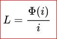
The inductance of a circuit depends on the geometry of the current path, and on the magnetic permeability of nearby materials; ferromagnetic materials with a higher permeability like iron near a conductor tend to increase the magnetic field and inductance. Any alteration to a circuit which increases the flux (total magnetic field) through the circuit produced by a given current increases the inductance, because inductance is also equal to the ratio of magnetic flux to current[14][15][16][17]

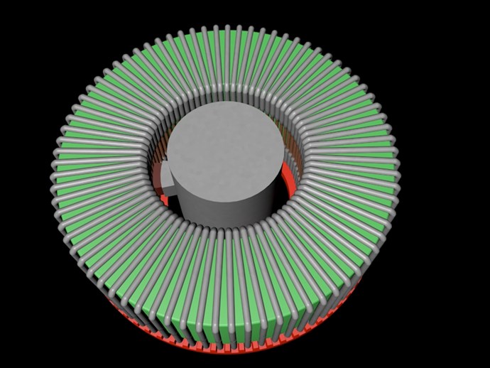
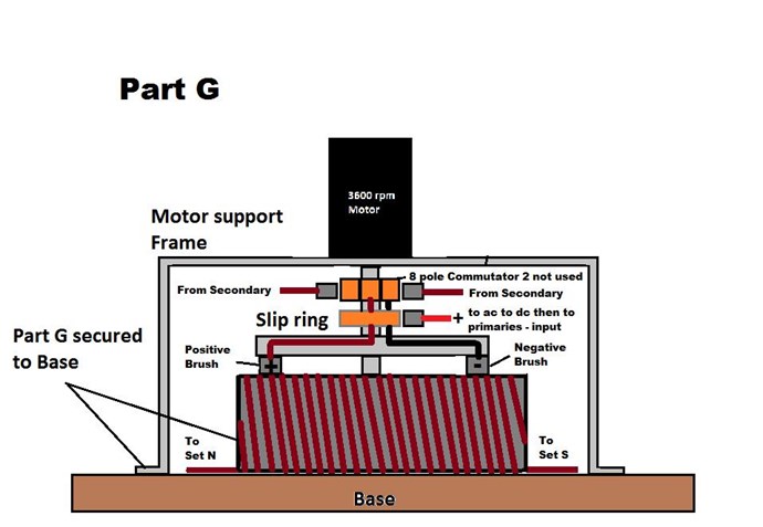
what this means is by increasing the magnetic field to currant ratio will in fact cause less currant to flow as the magnetic linking to the circuit increases thus the reverse EMF (C-EMF) to the original currant flow increases. so by rotating a positive brush making contact in a make before break scenario (Constant currant flow) you are constantly changing the ratio of magnetic field to currant on either side of the brush which has a N><N opposing fields to keep them separate but will remain in complete unison. as the brush rotates one link is taken away on one side but added to the other side keeping both primary electromagnet is complete unison. each time a loop is added it increases the magnetic field to currant ratio thus causing the currant reduction. the opposite is also true, with loops being taken away there will be a decrease in magnetic field to currant ratio thus more currant will flow. the reducing side will release that reduced potential while the increasing side is storing into the magnetic field for the next half cycle.

when the reduced currant situation happens as the circuit length is increased the stored magnetic field will release that reduced potential into the system with that of reduced potential of the reducing primary combined with the secondary loop back causes the amplification to the rising side of the system.

answers to your disbelief has been there all this time just waiting to be read and understood. the whole action from above is taking a passive inductor  from a static position to an active position then getting constant currant control as the positive brush rotates

thus concludes inductor advanced class 105. resistor 101 introduction was canceled due to fire damage in the bullding. ha, ha, ha, ha ! 

my grand father once told me that you learn until the day you die so from that it is never to late to learn as long as God gives you breath.


Marathonman

Attached Files

  • Liked by
  • Chris
Marathonman posted this 23 May 2018

Vidura;

Again another post of a circuit that was not proven in any way shape or form. we are not pursuing some fly by night circuit i dreamed up last week. i have been researching this device for almost 6 years and have proven everything on the bench and am here to build and share my findings. it would be highly appreciated if people would stop posting random ideas that popped into their head yesterday or last week and expect people that are actually doing tests i have already performed to drop what they are building to jump on your fantasy ideas.

If you would of read the entire post you would have realized we are already on a mission of provable Physics and really do not care to partake in your unproven circuit. i am not trying to be rude but random posting with no prior knowledge is rude in it's self and a disruption and distraction to the people building on this thread and the readers. if in the future when you have proven your circuit then you can get your own thread and post all you want.

until then it would be really nice if you read the entire thread and catch up to where we are all at in this present time. that way we will be on the same page. it is not about not posting, it's about catching up to us then post.

PS. we are not experimenting on idea's we are building the actual device in the patent.

respectfully,

Marathonman 

  • Liked by
  • Chris
Aetherholic posted this 23 May 2018

Peter

Good job with your design, I have something very similar pending tests with what I already have and seeing the results of Marathonman's epic C core solution.

With your arrangement you have the advantages of lower brush face velocity and centrifugal pressure is in the correct direction on the brush so I doubt you will need springs. Figuera may have used a wheel rather than a brush, in fact maybe 2 wheels slightly staggered to make sure a make before break for each brush.

For slip rings I recommend a commercially available solution. Most manufacturers can build what you need. The one I use can guarantee 200 million revolutions at 5A per channel (I have 6 channels in my new one just to use in parallel if I need) and 10 mOhm of noise. With something as complex as part G to build its just one less part I need to worry about as any interruption of the current flow will kill the overunity.

Aetherholic - One truth, One field

  • Liked by
  • Chris
Peter posted this 23 May 2018

Thanks Marathonman and Aetherholic,,

These sliprings sure look fine. I have tried  slip rings from an old vacuum cleaner before, but they are really flimsy, and i do not think they can handle the current. So i'll be ordering these online to.  

I still have one question about this part '

The addition of the secondary attached to the system is there to supply currant from losses and aides in the amplification process to the rising electromagnet.. The secondary feedback is commutated allowing both brushes to remain their sign always. yes, the secondary is mandatory for continuous operation replacing losses and amplification to the rising side of the device.

Could you post a schematic of how to attach the secondary to the system? Is the output from a secondary on a seperate 8 sided commutator connected with the - brush ??

Thank you, kind regards,


Peter


PS 200 million revs.. that's 46 days  24/7  at 3000 rpm (50Hz)

Marathonman posted this 23 May 2018

Yes peter the secondary is connected to a commutator so when the brush rotates it will allow the negative sign from the secondary to always remain opposite of the positive brush allowing the secondary to replace losses occurred and give rise to amplification to the rising side. one side of the commutator from the secondary input is connected directly to the positive brush and the negative is connected  to it's own opposite brush so when the motor is rotating the actions of the commutator will keep the signs in their proper place. this will allow part G to be the power supply when the external is removed.

i cant't say i have a schematic but below will give you a general idea what is to be accomplished.

Marathonman

  • Liked by
  • Peter

Topic Is Locked

We're Light Years Ahead!
Members Online:

No one online at the moment


What is a Scalar:

In physics, scalars are physical quantities that are unaffected by changes to a vector space basis. Scalars are often accompanied by units of measurement, as in "10 cm". Examples of scalar quantities are mass, distance, charge, volume, time, speed, and the magnitude of physical vectors in general.

You need to forget the Non-Sense that some spout with out knowing the actual Definition of the word Scalar! Some people talk absolute Bull Sh*t!

The pressure P in the formula P = pgh, pgh is a scalar that tells you the amount of this squashing force per unit area in a fluid.

A Scalar, having both direction and magnitude, can be anything! The Magnetic Field, a Charge moving, yet some Numb Nuts think it means Magic Science!

Message from God:

Hello my children. This is Yahweh, the one true Lord. You have found creation's secret. Now share it peacefully with the world.

Ref: Message from God written inside the Human Genome

God be in my head, and in my thinking.

God be in my eyes, and in my looking.

God be in my mouth, and in my speaking.

Oh, God be in my heart, and in my understanding.

Your Support:

More than anything else, your contributions to this forum are most important! We are trying to actively get all visitors involved, but we do only have a few main contributors, which are very much appreciated! If you would like to see more pages with more detailed experiments and answers, perhaps a contribution of another type maybe possible:

PayPal De-Platformed me!

They REFUSE to tell me why!

We now use Wise!

Donate
Use E-Mail: Chris at aboveunity.com

The content I am sharing is not only unique, but is changing the world as we know it! Please Support Us!

Thank You So Much!

Weeks High Earners:
The great Nikola Tesla:

Ere many generations pass, our machinery will be driven by a power obtainable at any point of the universe. This idea is not novel. Men have been led to it long ago by instinct or reason. It has been expressed in many ways, and in many places, in the history of old and new. We find it in the delightful myth of Antheus, who drives power from the earth; we find it among the subtle speculations of one of your splendid mathematicians, and in many hints and statements of thinkers of the present time. Throughout space there is energy. Is this energy static or kinetic? If static, our hopes are in vain; if kinetic - and this we know it is for certain - then it is a mere question of time when men will succeed in attaching their machinery to the very wheelwork of nature.

Experiments With Alternate Currents Of High Potential And High Frequency (February 1892).

Close