Clemente Figuera

  • Topic Is Locked
  • 49K Views
  • Last Post 16 July 2019
Wistiti posted this 09 January 2018


Hi guys!

In the past I play a bit with the Figuera concept. It use the POC as we already know the potential. I think this guy, Marathonman, understand the principe behind the Figuera device...

Chris, if there already a tread about Clemente Figuera, feel free to move this at the good place!


Order By: Standard | Newest | Votes
Marathonman posted this 29 October 2018

Good news is the guy that did the tooling on the brush holder called and said come pick it up...... as in freebe.

that means i will restart with my part G C core and my custom brush holder so all is not lost.

Regards,

Marathonman

Hopeful1 posted this 29 October 2018

Good news MM. someone is looking after you.

  • Liked by
  • Chris
  • Aetherholic
Marathonman posted this 02 November 2018

Working on transportation to pick up the brush holder this week end. i will take a pic and post when i get time.

Regards,

Marathonman

maarmuis posted this 03 November 2018

Thank you all and MM for all this info.

Years ago I attempted to build with resistor banks but soon discovered I was wasting my time.

With this new info from MM (makes perfect sense to me) as soon as finance allow, I will dust of the old toolbox again.

Thanx Again, cant wait to start!

Regards,

Maarmuis

PS. MM hope pray things turn out better for you.

Marathonman posted this 03 November 2018

Maarmuis;

You are quite welcome. Once the realization that Inductance can control current flow the device really makes sense. I am very happy with your realization of this fact. Happy building, should a question arise please feel free to ask away.

As the brush rotates the opposing fields in part G are constantly changing either increasing or decreasing in intensity which according to Faraday's Laws of Induction will create EMF within the circuit and according to the Lenz Law it will oppose the original current flow.

We are here to make a difference.

Regards,

Marathonman

Marathonman posted this 13 November 2018

You have to admit the sheer genius of Figuera that designed this device 110 years ago thus realizing the total lack of advancements or suppression of our Scientific and Physics community since then. if you ask me total greed has overtaken Corporate world to the point of a total control scenario.

using induced emf within the circuit (Self Inductance) to control current flow at a rate of efficiency in the upper high 90's is and will always be sheer genius. using an active inductor to control current flow, splitting the feed into two independent feeds using magnetic fields in total unison, forward biasing like a mag amp, storing and releasing potential at a specific time needed to offset the rising potential drop. then adding a portion of the output to replace the losses occurred and give rise to amplification to the rising primaries,   good god what a sheer genius Figuera was.

PS. i get an apartment of my own next week thus my lab/work bench will live again........ let the rebuilding of the Figuera device commence.

back in the saddle again.

Regards,

Marathonman 

maarmuis posted this 13 November 2018

Welcome back MM.laughing

Cornboy posted this 22 November 2018

 Hi all,  @ Aetherholic, hope your testing is going well.

 With your generator cores, are you having a problem with magnetic reminiscence?

 With your Part G core, do the C's butt together and the I fits between or do the C's butt onto the I section separating the C's.

 Also with G winding how many wires at a time does the brush span?

 Hope you don't mind questions, will try to keep to a minimum.


 Warmest Regards  Cornboy.  smile

  • Liked by
  • Chris
Aetherholic posted this 23 November 2018

Cornboy

The cores:

My triplet core material, as I posted before, is DT4C which is very fast and has zero residual magnetism. Even though I was getting good results I did not see the correct field from the cores during testing but I got side tracked investigating other anomalies which has taken up a lot of time including by the way, as you experienced, why its so easy to blow 100A diode bridges with this system. Last week I returned back to looking at the cores and the material as I managed to find a BH curve for DT4C so that I could simulate it. I have run thousands of simulations on different materials and core coil configurations so I suspected that there was a material problem. When I ran the simulation with DT4C BH curves the results were similar to using Hyperco 50 so I then confirmed that the triplet cores I have must have a problem. After a few days of research I narrowed it down to the annealing process which needs to be very specific for this material so I spent 2 days dismantling the 21 coil cores which was a major job and yesterday took them to a specialist annealers. Today they are going through the process so I expect to get them back at the weekend and rebuild.

The CIC core: The I section fits between the two C sections like this: [ | ] with the winding on the I section.

The brush spans 5 windings at the mid point of the winding length and 4 windings at the two extreme points, entirely due to my particular winding/brush size geometry. I wound my winding with the largest face flat to the core. The other way is to wind with the shortest face flat to the core but my hand winding skills are not that good to attempt to do that.

I hope this answers everything, let me know if I missed something.

On another note to everyone, please be careful when testing. There are HOT AND COLD currents of high magnitude flying around within the system.  One of the 100A diodes I blew up was with cold current and one of my fingers in the conduction path, no damage but not something I dont want to repeat anytime soon.


Aetherholic - One truth, One field

  • Liked by
  • Vidura
Cornboy posted this 23 November 2018

Cornboy

The cores:

My triplet core material, as I posted before, is DT4C which is very fast and has zero residual magnetism. Even though I was getting good results I did not see the correct field from the cores during testing but I got side tracked investigating other anomalies which has taken up a lot of time including by the way, as you experienced, why its so easy to blow 100A diode bridges with this system. Last week I returned back to looking at the cores and the material as I managed to find a BH curve for DT4C so that I could simulate it. I have run thousands of simulations on different materials and core coil configurations so I suspected that there was a material problem. When I ran the simulation with DT4C BH curves the results were similar to using Hyperco 50 so I then confirmed that the triplet cores I have must have a problem. After a few days of research I narrowed it down to the annealing process which needs to be very specific for this material so I spent 2 days dismantling the 21 coil cores which was a major job and yesterday took them to a specialist annealers. Today they are going through the process so I expect to get them back at the weekend and rebuild.

The CIC core: The I section fits between the two C sections like this: [ | ] with the winding on the I section.

The brush spans 5 windings at the mid point of the winding length and 4 windings at the two extreme points, entirely due to my particular winding/brush size geometry. I wound my winding with the largest face flat to the core. The other way is to wind with the shortest face flat to the core but my hand winding skills are not that good to attempt to do that.

I hope this answers everything, let me know if I missed something.

On another note to everyone, please be careful when testing. There are HOT AND COLD currents of high magnitude flying around within the system.  One of the 100A diodes I blew up was with cold current and one of my fingers in the conduction path, no damage but not something I want to repeat anytime soon.


 Thanks Eatherholic, using your G core that way would be similar to an EI but with rounded corners and different material.

 I wouldn't have thought that the core annealing would be so critical, compared with what was available back in Clemente's era, it will be interesting to see the results.

 How do you see the fields from the cores, and what should they look like?

 Are you using the diodes to feed back from the secondaries to the positive brush?

 I too have had similar shocks while experimenting, scares the bejesus out of ya when your not expecting it, lol.

 Something to remember with mechanical switching, even if you can't see a spark at the brush, the tiniest one will allow all frequencies to be available to your system, which can cause unexpected resonances to develop.

 That being said, i believe that mechanical switching, in the 1800's early 1900's was part of the overunity phenomenon we are all chasing, and cant be replaced with modern day silicon switching.

 Take Care, regards  Cornboy.   smile   

Aetherholic posted this 23 November 2018

Cornboy

Please look back in the posts and you will see I posted FEMM simulations for the triplets and discussed the fields.

For feedback I have the option of commutator, diodes or both. I was experimenting with all options to see the differences.

Brush based methods have the advantage of passing both hot and cold currents, only some semiconductors can pass the cold current. For figuerra we explicitly need zero sparking. The difference between sparking and not is huge, sparking is definitely useless in this system.

Aetherholic - One truth, One field

  • Liked by
  • Chris
  • Cornboy
Cornboy posted this 23 November 2018

 Thanks Aetherholic, i did read right through before i started posting and will revisit.

 Understand about sparking, just have never seen a carbon brush delivering current, that never sparked at least slightly, which is all it takes to cause anomaly's, sometimes unexpected.

 I believe that in Doug1's device he was amazed at how little the brush sparked!.


 Warm Regards  Cornboy.  smile

  • Liked by
  • Chris
Marathonman posted this 24 November 2018

One has to remember that Mr Doug precision ground part G's brush face. This is the major reason there was no sparking, something people seem to be forgetting. Using a high speed table top drill press with a high speed sanding disc will get one the precision flatness needed at a cheep price.

Permeability of your cores has a major factor in deciding your core material, to fast and the fields will collapse to fast not maintaining the proper feed back to the system.

Smart move annealing your cores Aetherholic.

Regards,

Marathonman

Aetherholic posted this 26 November 2018

The annealing process worked so now I am rebuilding everything.

Aetherholic - One truth, One field

Marathonman posted this 27 November 2018

This is good news Aetherholic just glad it was something simple.  what were the final specs on the cores?

if you plan on a 100 volt test i will be VERY much interested in that results, 

also how is your part G working out for you.?

Regards,

Marathonman

  • Liked by
  • Chris
  • Cornboy
Aetherholic posted this 27 November 2018

Marathonman

I ran a quick static test to confirm the field now agrees with simulation and then a test using Part G on a single triplet. With 14V 20A into Part G I got 20V AC output from the output coil. Now I am rebuilding the rest of the triplets and wiring them up as before so in a couple of days I hope to have some further results.

My Part G seems to be functioning well so we will see what happens now the cores have the correct field and I can start to apply the correct voltage for feedback.

Best regards,

Aetherholic - One truth, One field

  • Liked by
  • Marathonman
  • Cornboy
Marathonman posted this 27 November 2018

I know i overbuilt my part G core but it will still be just fine. it can be scaled down in the future to 4 or 5 inches when into production and replication. the whole point was to get the most efficient Inductor i can by using the thickest and usable wire i can with the least amount of resistance. of course cost of the wire has to be considered and rectangle wire is not cheap of easily handled so that is why i chose the square wire rout.

i am very glad you are back on track.

regards,

Marathonman

Marathonman posted this 28 November 2018

Other than having two primaries in the first link those two devices have absolutely nothing in common with the Figuera device what so ever. Not even switched the same either or on the same concept. So i find very hard to justify your statement of 100% Figuera, it seems you need to rethink your understanding of the Figuera device and his techniques he used to get hia device running like a standard generator. any thing else is NOT the Figuera device in any way shape or form.

interesting yes, 100% Figuera NO.

Regards,

Marathonman

alset posted this 28 November 2018

This guy seems to use 100% Figuera teachings:
https://overunity.com/17535/kapanadze-stepanov-barbosa-leal-and-the-secret-of-free-energy/msg516346/#msg516346
https://overunity.com/17535/kapanadze-stepanov-barbosa-leal-and-the-secret-of-free-energy/msg517669/#msg517669
Just to show some posts that I found very interesting

Two electromagnets, one output intermediate coil, two exciting signals in counterphase, always positive and when one at maximun the other at minimum, electromagnets in repulsion... All Figuera teachings.  

Note that two AC signals where one is 90° unphased  with a capacitor when they are rectified they become in two 180° unphased signals, so when one is at maximum the other is at minimum

I was refering to the teachings described in the 1908 patent which I attach here (never it is late, even after 600 posts, that someone post the patent here)


Attached Files

  • Liked by
  • Chris
  • Cornboy
Marathonman posted this 29 November 2018

One of the major keys of the Figuera device is to use Dc and only reduce the current just enough to get the sweeping action across the secondary without reducing the field to the point of losing pressure between them. If one was to use AC all pressure would be lost between the primaries and induction will be reduced to just the rising electromagnet. This is the reason why generators use DC in their exciting field. as for the patent, it had been posted so many times in the past i never thought about it not being posted here. maybe it got deleted.

yes the devices are similar but when you study in great detail may things change.

Regards,

Marathonman

alset posted this 01 December 2018

This guy seems to have a working device, and the driving system is really simple (with diodes). At least that is what I get after translation of his original post (not in english). He states to use around 1A to excite the system and get it working. I haven't found any other newer post after the one in which he said  "---it works---"  :

http://overunity.com/12794/re-inventing-the-wheel-part1-clemente_figuera-the-infinite-energy-machine/msg501929/#msg501929

The input driving signal is filtered while crossing the electromagnets (RL filter: the higher the ratio L/R the higher is the filter effect) so maybe an input signal reaching zero after the filter effect does not reach that zero level and may keep some current circulating during the off pulses. By using this filter effect he was constrained to the value of L/R of the system. So maybe he had to adjust the current to around 1A because it was his only degree of freedom to tune his device. Maybe it would have more flexibility if he could have the option to adjust the max and min values.

I agree that it should be a valid range of max and min current to sweep the whole secondary length. If I have understood fine this system is just a balance of two forces moving along the output coil from side to side. Am I right?


  • Liked by
  • Chris
Marathonman posted this 01 December 2018

Essentially yes with other parameters involved. The device you linked to is similar to the Figuera device but the switching and coil setup is different. I have posted the working parameters of the Figuera device many, many times and even though they are similar they still are not the Figuera device.

Good luck in your pursuits.

Regards,

Marathonman

alset posted this 02 December 2018

Until now all the discussion has been focused in the patent from 1908 and its driving signals. Two senoidal waves unphased 180°.


But in 1902 Figuera filed another patent, that I attach to this post, with the same configuration (two confronted electromagnets and one intermediate output coil). In this patent he states that the driving signals are intermittent or alternating signals.


From both patents, from year 1902 and year 1908, I guess that the driving signals are not very restricted in their shapes to get the expected effect. Probably it is important to adjust them to each particular system in order to get the result: Maybe max/min values and frequency. Probably with the driving signals in the 1902 the output was not pure AC wave (maybe a current to be stored into a battery for later use), while he got real AC wave by optimizing the patent by using his commutator in the 1908 patent with the two unphased senoidal waves. Output ready to be poured into the mains.

Attached Files

  • Liked by
  • Chris
Marathonman posted this 02 December 2018

Alset, you do know we are pursuing the 1908 patent and that it is DC driven don't you.? There is no way Ac can be used in the Figuera device because AC looses induction at zero plus takes to long to flip magnetic domains thus why DC is used and reduced just enough toget the sweeping action then back to full potential. all this has been discussed on multiple web sites a long time ago.

Marathonman

alset posted this 04 December 2018

One device very similar to the Figuera generator: two electromagnets in repulsion and between them some coils to pickup the energy. Excited with a pulsed signal. This is the device by Daniel Dingel who built a car moved by HHO

Repulsion seems he way to go. Atracction is just a transformer. I also read that maybe Floyd Sweet also used two input coils in repulsion (bucking coils) 


  • Liked by
  • Chris
Marathonman posted this 04 December 2018

I personally think you are here to disrupt this thread because this is the Figuera thread and you have posted not one thing about the Figuera device or anything that hasn't been added or associated years ago. nor have you asked any pertaining to the device.

spammers do the same thing as does people that were here to disrupt or discredit. so what category do you fall in.

if you want to know how the device operates all you have to do is read and study what has been posted but i guess everyone knows what your true agenda is.....well at least i do.

Marathonman

  • Liked by
  • Cornboy
alohalaoha posted this 08 December 2018

Hey Marathonman

I want to know your oppinion - does this drawing of Figuera BTG is correct or not ?

If not what should be changed ? Could you make your know-how notes about this Figuera circuit schematic ?

ps: I am interested only in aspects of short circuiting different partnered bifilar configurations, and power output.


Best wishes

Aloha


Marathonman posted this 08 December 2018

I see no drawing just a box. Maybe it is my phone so i will review on computer tomorrow.

Marathonman

alohalaoha posted this 09 December 2018

Thank you Marathonman !

Best regards

Aloha


Marathonman posted this 10 December 2018

alohalaoha '


  i still do not see the pic or drawing you are referring to.

can you repost so can review.

Marathonman

alohalaoha posted this 10 December 2018

Thanks Marathonman

I have uploaded here on forum and also here

Regards

Aloha

Attached Files

Marathonman posted this 10 December 2018

The Figuera device uses an active Inductor for part G that changes the magnetic flux to current ratio which according to Faraday any change in flux produces EMF and according to Lenz it will oppose the original current flow. along with that it stores and releases potential at a specific time to add the rising primaries to maintain the pressure between the primaries to sustain ongoing Induction.

the primaries are reduced and increased to induce motion into the secondary and once current begins to flow in the secondary and the load a second field will form according to the lenz law that will oppose the original current flow. once this happens the primaries and the secondaries part ways and it is just the realitive motion of the primaries that induce motion into the secondaries. after this polarization no other time is the potential circulating in the inducing system is tranfered to the induced system. they are essentially two separate systems from then on just like a standard generator system.

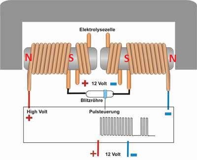
as the brush rotates the current through the primaries are reduced and increased 180 degrees out from each other causing the Electric fields to be in the same direction being positive and additive. the primary and the secondary cores are separated to stop eddy currents and hysteresis from interferrring from the action of the AC in the secondaries to the primaries.

with the lenz field from the secondary sandwiched between the primary fields the primaries are raised and lowered in intensity just to clear the secondary coil then back to full potential while the other is reduced.  in this action of reducing and increasing  the magnetic fields stay opposing while the Electric fields joiin as one. in this set up the peaking of the primaries need to be symetyrical, meaning the peak of the primaries needs to be the same or induction will be lost thus reduced to just the rising primaries.

there are two primariy facing each other being north face opposing electromagnets with the secondary located between them with an active inductor used as the controller controlling the current flow through the primaries.

if you do not have your setup like this or your coil core arangement is different then congratulations you are NOT working on the Figuera device 1908 patent. anything other is just that something other than the 1908 patent and i wish you luck in your pursuit.

this thread is according to my knowledge following the 1908 patent of Clemente Figuera patent in Barcelona Spain in 1908 that powered his house lights, a 20 HP motor and all the street lights around his house.

Regards,

Marathonman

  • Liked by
  • alohalaoha
alohalaoha posted this 10 December 2018

Hey Marathoman,

Thank you for detailed explanations.

It is a truth that "All new is old time forgotten old" like in Russia said. Figuera is one of first who had discovered anomaly effect of bucking coils.

What i could comprehend about Figuera till now without deep study in details, that his system is acting like balancing on the edge.

Two currents start flowing into two opposite sides of each primary. These curents induce two seconary's magnetic fields opposite to each other and again opposite to the primary magneic fields. These two opposite fields are additionaly compressed by two primary fileds. As the result, load coil which is magneticaly coupled to the both, sees these compressions like two sinchronised motional electric fields, which create additive electro motive force across the load.

Good luck

Aloha

Marathonman posted this 13 December 2018

The magnetic fields of the secondaries are loosely coupled at best as it is the Lenz field that is swept from side to side across the secondary. all fields are opposing except for the original current flowing in the secondary.

it is quite hard for people to grasp the idea of the lenz created field in the secondary that is what is swept from side to side. on that note a load has to be attached to the secondaries in order for the device to operate properly because if the load is not present the current will not flow and the Lenz field will not form. if the field is not present the primaries can not induce motion into the secondaries giving the illusion of motion to the Electric field formed by the primaries in their increase and decrease of their magnetic fields.

I see you have a fairly good grasp on what is taking place in the Cores of the Figuera device.

Regards,

Marathonman

  • Liked by
  • alohalaoha
alohalaoha posted this 14 December 2018

Marathonman what kind of load Figuera device prefer pure resistive or mixed with capacitive and inductive component.

Would be very hard to tune output to pure resitive load Z= R +/- jx0 withouth network analyser. Figuera device is a partnered bucked system, so it is directly winding lenght dependent. As you already know partnered coils we can visualise like a short-circuited transmission line.

That's all. I didn't came here to bother you and make empty talks, only to hear from the first hand what do you think ?

Thanks for your detailed explanations and replies to my posts.

I wish you success, and good luck.

Reg.

Aloha

  • Liked by
  • Vidura
  • Chris
Marathonman posted this 14 December 2018

No problem alohalaoha  any questions are not a bother and one must ask questions to learn.

Figuera  ran a 20 Hp motor and his street lights so i will leave you with your capacitive, inductive and purely resistive load question with an answer of all of them. 

my personal tests did not get that far but they will in the future.

Regards,

Marathonman

  • Liked by
  • alohalaoha
  • Chris
Peter posted this 21 December 2018

Wishing all you builders  happy holidays( if you got one) and the best new year (with loads of excess energy).

Finished annealing my cores, got my copper wire. Christmas time is coil winding time   HOHOHO...

  • Liked by
  • Wistiti
  • Chris
Marathonman posted this 21 December 2018

Thank you Peter, and happy Holidays to you also.

it is good you have progress and i to am getting the bench back together.

HAPPY HOLIDAYS EVERYONE !

Regards,

Marathonman

  • Liked by
  • Peter
  • Chris
Cornboy posted this 21 December 2018

Have great time off everyone, glad to see you back at it Peter and MM.

 I too will have a bit of play time shortly.


 Best regards  Cornboy.   smile

  • Liked by
  • Peter
  • Chris
Marathonman posted this 27 December 2018

People please listen to these words i say now, " Inverse square law and the square of the distance."

in a transformer and a standard generator you have poles that are high pressure and a pole that is low pressure that causes the high intensity fields. in the Figuera device we have a duel mono pole excitation system that conforms to the inverse square law.

in my own test i confermed this to be true, the magnetic fields will only project out as long as the core it is coming from whether it be magnet or electromagnet.

a 3 inch core will only project out 3 inches thus if you have a 3 inch primary and a 3 inch secondary your field will be so week by the time it gets out three inches it will be Zero pressure. it can not  project out pass the secondary core even without the other primary in place.

in the 1908 patent it shows the core twice that of the secondary which has very substantial merit according to the inverse square law and in research it shows that any builder of the Figuera device that has the cores the same size will Never get an output  worth squat.

I am working on a you tube video at this moment that explains this in very much detail as to why it is so and why no one is getting anything out of their build.

start building your primaries twice the size as your secondaries.......2 to 1 ratio and you will be rewarded.

regards,

Marathonman

romanta posted this 28 December 2018

Good day to all. In the old year I began a series of experiments on the topic of Figuera, at the moment what MM says is true. after I made the secondary coil half shorter, I got a much larger power output. I plan to cut the coil still, and see what happens, with the same input parameters of the primary coils.This is up to change.This is after the change.

Cornboy posted this 28 December 2018

 Hi Romanta, thanks for posting your results here and Welcome.

 If you don't mind me asking how do you switch your drive coils, and what do you use for resistance in your circuit?.

 Best Regards  Cornboy.   smile

romanta posted this 29 December 2018

 Hi Romanta, thanks for posting your results here and Welcome.

 If you don't mind me asking how do you switch your drive coils, and what do you use for resistance in your circuit?.

 Best Regards  Cornboy.   smile

And I apologize in advance for my poor English, this is not my native language.

My coil power circuit is standard for powering the push pool. This circuit is not intended to work with the Figuera device. Power to the entire device is not more than 18 volts. Current 5A. I just check how the coils work with different directions of the magnetic field and with different secondary coils.SHEM

romanta posted this 29 December 2018

I also want to conduct an experiment using a copper washer at the end of the solenoid. As is known from old sources, a short-circuited turn of the wire at the end of the solenoid does not allow the magnetic field of the FAST core to leave the core. What will come of this, I will know only after the experiments in the new year of January 9th. because my lab will be unavailable.

Do not understand this as a deviation from the original Figuera device, I just want to make the device more economical in its work.

Cornboy posted this 29 December 2018

 OK Thanks Romanta, understand.


 Regards  Cornboy.  smile

  • Liked by
  • Chris
Marathonman posted this 29 December 2018

romanta;

  Thank you for confirming my results.

although i am skeptical of your signal approach i applaud you for your innovation. in your circuit.  how do you plan on recycling the power in the inducer side of the system remembering both inducer and induced are two separate  systems.

The inverse square law is directly applicable to the mono poles of the Figuera device and i am very glad you realized this at an early stage in your build. the magnetic field must be able to project passed the secondary if one is to maintain the pressure when reduced.

CONGRATS ! you are one of the very few that listened to sound advice.

PS. Welcome aboard.

Regards,

Marathonman

Marathonman posted this 31 December 2018

YES ! you heard me right, the Figuera device is a DUEL MONO POLE EXCITATION SYSTEM that does not utilize both poles as does a standard generator to attain the high intensity field. it uses two mono poles to compress the field lines to that of a standard generator then increases one and reduces the other to create not only the Electric fields in the same direction but to also induce motion into the secondary.

I am purchasing the chart boards tomorrow for the video i am in the midst of making explaining the Inverse Square Law in full and why it is directly applicable to the Figuera device.

Use the 2 to 1 ratio and watch the oyster open up.

Happy new year.

Regards,

Marathonman

Marathonman posted this 04 January 2019

Some might say that the Inverse Square Law doesn't apply to magnetism and that other Laws apply. i say BS. if it deals with the Electric fields, Radiation and such you can darn well bet it applies to the magnetic field also.

do the tests at your shop or home and verify what i have stated. my own tests proved the magnetic field conforms  to the Inverse Square Law to the Tee.  if you have a 3 inch primary your field emanating from that 3 inch core will only be 3 inches because it is reducing in intensity by the square of the distance.

so if you have a 3 inch primary and a 3 inch secondary the field at the end of the secondary emanating from the primary will will be BARELY detectable and in no way can you maintain the required pressure between your primaries. all you people thinking a 3 inch primary will project out 6 inches needs to rethink your approach as this will never happen in my life time, your life time or on Mars.

from now on make your primaries no less than double the length of your secondaries and your oyster will open.

Regards,

Marathonman

  • Liked by
  • Aetherholic
  • Chris
alset posted this 05 January 2019

Then a 3-inch long primary has the same magnetic force no matter if it has 100 turns or 1000 turns.

I never thought that length was more important than N•I^2

Keep on the good work!

  • Liked by
  • Chris

Topic Is Locked

We're Light Years Ahead!
Members Online:
What is a Scalar:

In physics, scalars are physical quantities that are unaffected by changes to a vector space basis. Scalars are often accompanied by units of measurement, as in "10 cm". Examples of scalar quantities are mass, distance, charge, volume, time, speed, and the magnitude of physical vectors in general.

You need to forget the Non-Sense that some spout with out knowing the actual Definition of the word Scalar! Some people talk absolute Bull Sh*t!

The pressure P in the formula P = pgh, pgh is a scalar that tells you the amount of this squashing force per unit area in a fluid.

A Scalar, having both direction and magnitude, can be anything! The Magnetic Field, a Charge moving, yet some Numb Nuts think it means Magic Science!

Message from God:

Hello my children. This is Yahweh, the one true Lord. You have found creation's secret. Now share it peacefully with the world.

Ref: Message from God written inside the Human Genome

God be in my head, and in my thinking.

God be in my eyes, and in my looking.

God be in my mouth, and in my speaking.

Oh, God be in my heart, and in my understanding.

Your Support:

More than anything else, your contributions to this forum are most important! We are trying to actively get all visitors involved, but we do only have a few main contributors, which are very much appreciated! If you would like to see more pages with more detailed experiments and answers, perhaps a contribution of another type maybe possible:

PayPal De-Platformed me!

They REFUSE to tell me why!

We now use Wise!

Donate
Use E-Mail: Chris at aboveunity.com

The content I am sharing is not only unique, but is changing the world as we know it! Please Support Us!

Thank You So Much!

Weeks High Earners:
The great Nikola Tesla:

Ere many generations pass, our machinery will be driven by a power obtainable at any point of the universe. This idea is not novel. Men have been led to it long ago by instinct or reason. It has been expressed in many ways, and in many places, in the history of old and new. We find it in the delightful myth of Antheus, who drives power from the earth; we find it among the subtle speculations of one of your splendid mathematicians, and in many hints and statements of thinkers of the present time. Throughout space there is energy. Is this energy static or kinetic? If static, our hopes are in vain; if kinetic - and this we know it is for certain - then it is a mere question of time when men will succeed in attaching their machinery to the very wheelwork of nature.

Experiments With Alternate Currents Of High Potential And High Frequency (February 1892).

Close