Hello marathonman,
Thankyou for your down to earth analysis of what I presented.
I have read many of your Posts but did not initially agree with the 'R' being an 'L' but in looking at the drawing now, as a suggestion, I see it in 3D and the 2nd coil line is at the back of the large drum it is wound on and I hope others can also see this as it is a long coil on a large drum with the 2nd/4th/6th etc turns actually at the back of the drum where we would normally show these in faint or dotted lines.
Why is there a frame around this 'R' device and is it drawn such so as to confuse?
Perhaps this is the reason also why the coil is slanted to the right as that is how you would wind it.
Yes, OK in retrospect and what you are connecting with in your theory is a high possibility.
Will wind a 1/2" coil on a 3.5" plastic drum using awg 20 and see what we can determine in the circuit.
OR do we wind on an Iron bar or pipe as we need to couple to neighboring wires?
Why would this part be called 'R' when that is exactly what it looks like and with reference to Tesla's Colorado Springs Notes of about the same vintage of 1900, a resistor is a sawtooth shape with coils in a loop which confirms your observation.
That's why I used Manganin (Nichrome) wire as that is what that object appeared to me and was discovered in 1905 and suggesting it may have been available by 1909 when the Patent was applied for.
As there was no awg wire sizes mentioned, I did some testing with the many coils I had here all prewound which I had scored on Ebay.
Their physical size was near all the same and why I chose a 1/2" threaded bolt as the core and to my surprise their wire size ranged from 28 to 32 awg with a large range of resistances.
What was also noted was that the 'R' and 'L' values were nearly all the same and as an example - 34ohm/39mH-18/19- 3.4/3.3 - 8.3/7.4 - 2.0/2.3 - 20.8/18.0 - 12.0/12.0 - 12.1/13.5 - 1.5/1.2.
However what was also recorded was the current consumed at 12volts with the lower 'R' having the highest draw at 4.4 amps typical and the higher 'R' at 0.4 amps.
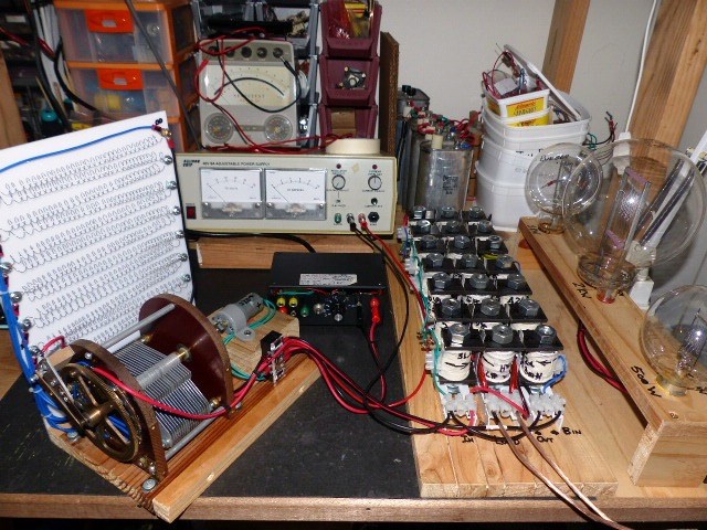
I have no idea what these wound cores were used for but was the reason why they were used and utilised 7 of these in the input sides, having to wind another 7.
I also did a bolt attraction test after these had been prepared ready for fixing on their plastic 'L' base and all had very similar attraction distances.
However there remains the voltage drop problem with the input coils being in series where the first coil receives the full 12 volts but then degrades by 1.5 volts each time it hits a coil in the 7 line up.
As soon as I changed this to series parallel, I obtained a mV output and you could see the sine wave being formed and also the coils being energised.
Again for the output coils, I had also wired up in series parallel as my thoughts there was that you were relying on each coil to add the voltage of the one before in the string line and the last would have the full load on its meagre windings.
Anyway, this is all a part of sorting out what we don't know and will continue with tests.
An original picture would be helpful at this point, don't you all agree?
David G


 Nice Price-tag also


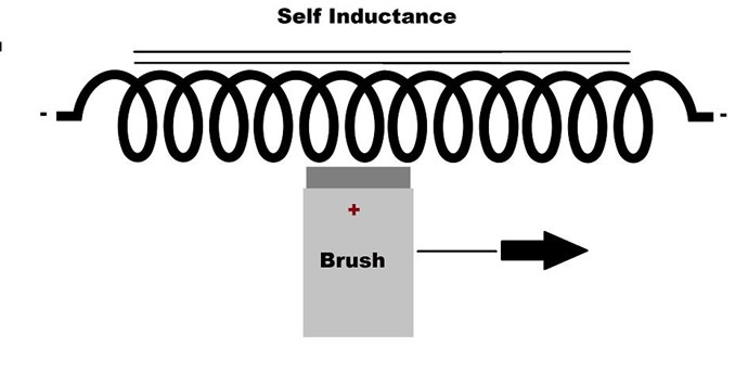


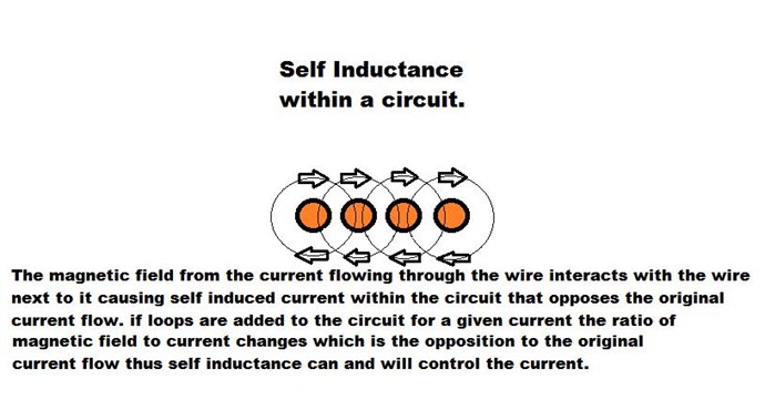
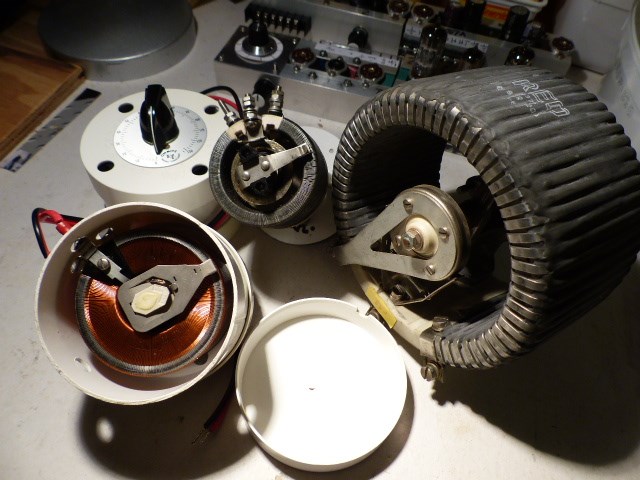
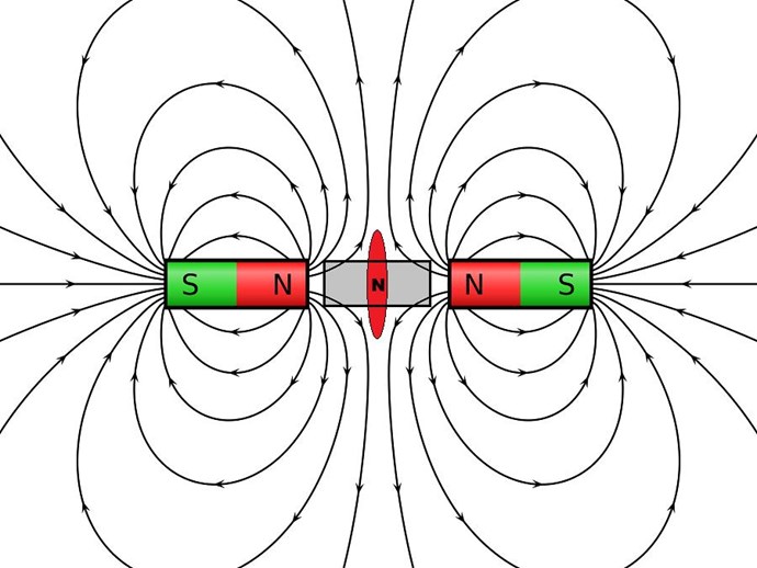
 you get an Inductor with a rotating brush that constantly changes the loop count that magnetically link to that side of the circuit that produces an opposition to the original current flow. as the brush rotates so does the change in magnetic field to current ratio witch is the amount of opposing EMF to the original current flow.