Marathonman,
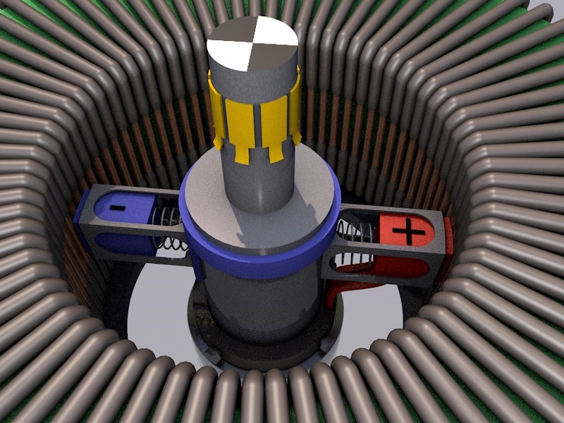
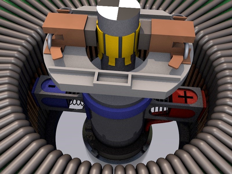
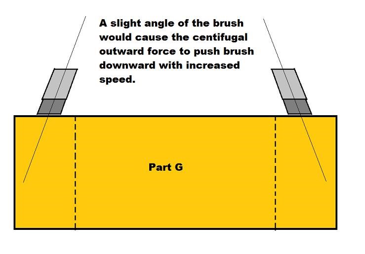
Here's a little animation i made showing the brush settings along with the potentials in both primary's.
Please correct me when i am wrong, but i think that this is how it's supposed to work
sorry for the video compression, that's on VIMEO.
The video does not repeat but you can pause the video, and scroll through.
A short explanation, and please correct me if i am wrong MM..
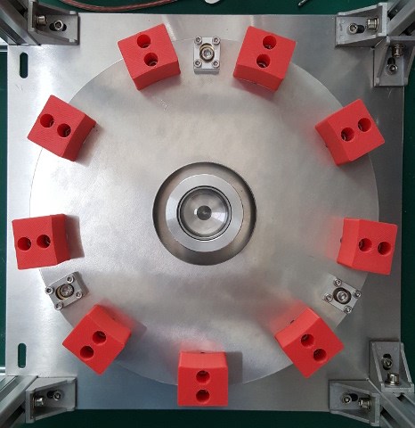
If the positive brush (red) is at 9 O'clock (points to the left) The red primary will have maximum potential.
The blue primary will have minimal potential (not zero !!, never to zero)
The positive brush (red) turns CW, and as it hits the 3 O'clock mark, the red primary will have minimal potential (not zero!!)
and the blue primary will have maximum potential.
The positive brush keeps turning, and the previous sequence will repeat from 3 until 9 again.
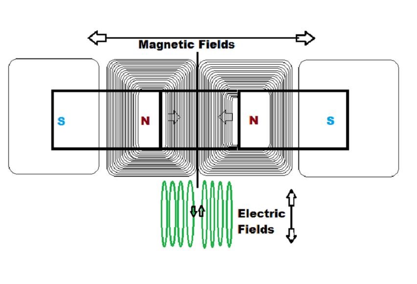
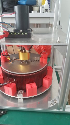
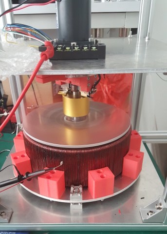
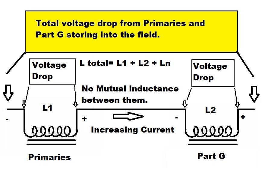
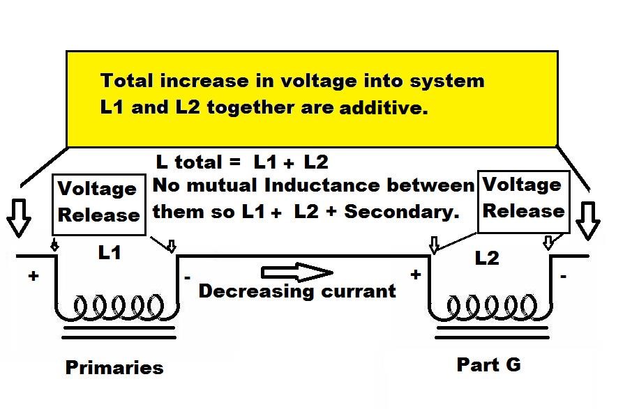
I tried to also show the induced magnetic fields of each coil. blowing up one, and schrinking the other
These two fields will push and pull the secondary's magnetic field from left to right, sweeping it across the secondary.
This will happen 50 times per second, as the brush rotates with a speed of 3000 rpm.
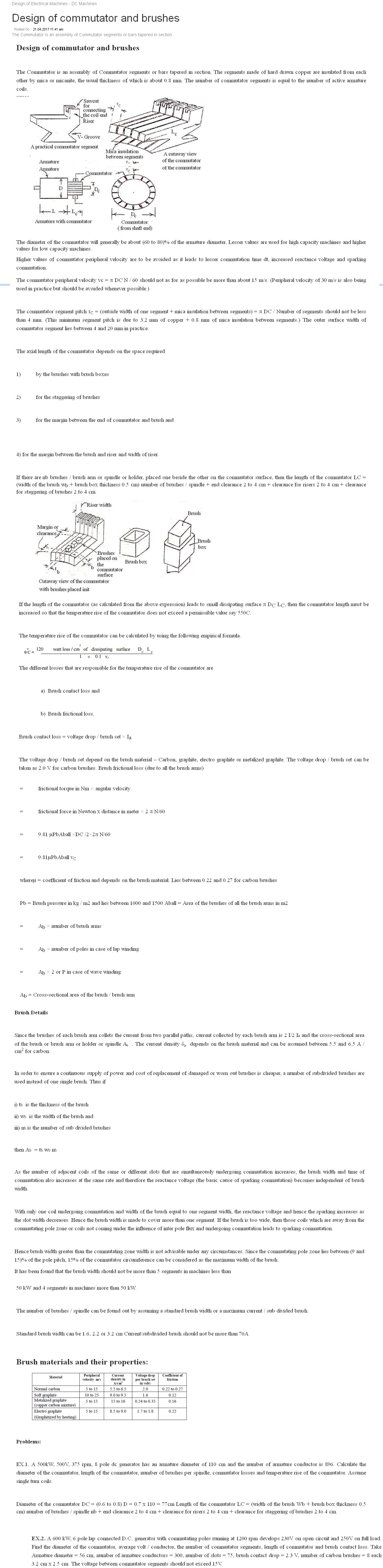
The commutator peripheral velocity vc = π DC N / 60 should not be more than about 15 m/s.
(Peripheral velocity of 30 m/s is also being used in practice but should be avoided whenever possible.)
Higher values of commutator peripheral velocity are to be avoided as it leads to lesser commutation time dt,
increased reactance voltage and sparking commutation.
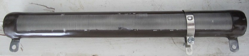
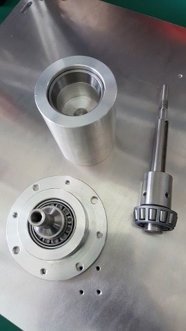
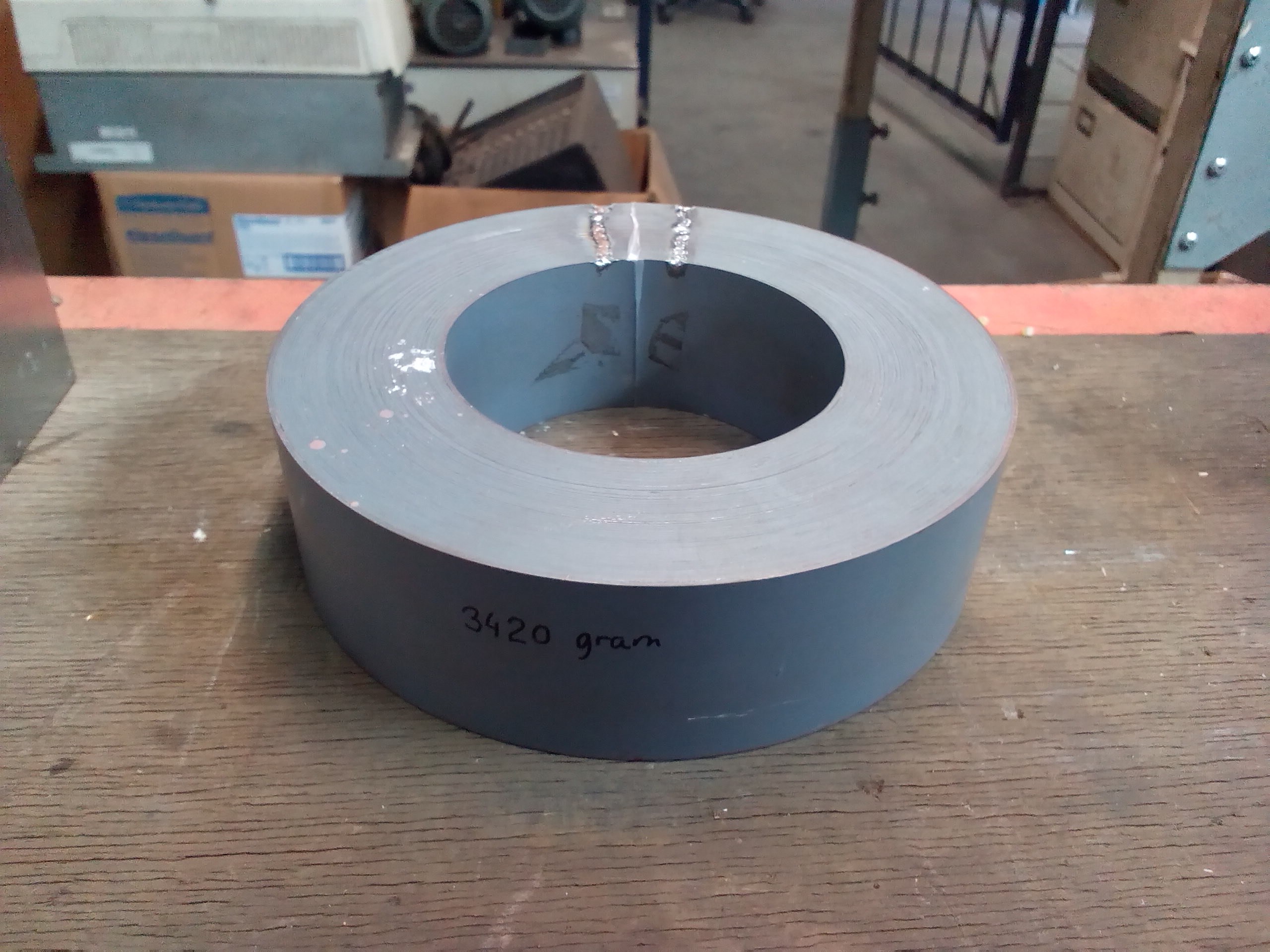
The inner diameter of my part g is 76 mm, so the peripheral velocity from my inside brushes is about 6,25 m/s @ 3000 rpm
kind regards,
Peter