Clemente Figuera

  • Topic Is Locked
  • 49K Views
  • Last Post 16 July 2019
Wistiti posted this 09 January 2018


Hi guys!

In the past I play a bit with the Figuera concept. It use the POC as we already know the potential. I think this guy, Marathonman, understand the principe behind the Figuera device...

Chris, if there already a tread about Clemente Figuera, feel free to move this at the good place!


Order By: Standard | Newest | Votes
Aetherholic posted this 27 August 2018

Marathonman,

I sympathize deeply. As scheduled my amorphous 25 micron laminated CIC core arrived, in pieces and de-laminated by the wonderful delivery company who managed, on a journey of 100km to totally trash it despite it being in a wooden crate. Words fail me...........

So the supplier will have to make a new one. More delays due to incompetence. 

The good news is I completed the framework for the entire generator, managed to source and get the rectangular wire for the core, sorted out my winding machine to correctly wind the 2.1mm wire for the coils, lasercut all the parts for the frames to hold each triplet and the coil bobbins, sourced and received the commutator, slip rings and bearings for the new part G and take delivery this week of all the new cnc parts.

So by the time a new core arrives, assuming it survives the Paris-Dakar rally conditions of the delivery service, I will have everything else in place on the frame.

Aetherholic - One truth, One field

Marathonman posted this 27 August 2018

Apparently "FRAGILE DO NOT DROP" means nothing now a days and the heavier it is the worse it gets tossed. these younger generations are the worst.

Regards,

Marathonman

Marathonman posted this 27 August 2018

Yay ! Dremel to the rescue. i figuered the main tool is ok but the little attachments are total junk so i picked up an actual Dremel tool kit and voila, i got the bobbin ready for winding.

last pic is the first layer.

You sure get what you pay for these days.

regards,

Marathonman


  • Liked by
  • Aetherholic
  • Chris
Marathonman posted this 29 August 2018

At the third layer and everything is going very well. the bobbins i make are so strong they can withstand a lot of punishment and are definitely easy to wind compared to winding directly on the core. leaves room for adjustments on the core also. one thing i did do different is add a second ring to the wire end for more support because of the weakening after i cut the four groves for the wire. much stronger than my last ones.

Regards,

Marathonman

  • Liked by
  • Chris
  • Aetherholic
Marathonman posted this 29 August 2018

Finished Primary.

Regards,

Marathonman

  • Liked by
  • Aetherholic
Aetherholic posted this 30 August 2018

I am also busy building....

First completed triplet:

In position on the frame:

And yes, the threaded rods and nuts and washers are non magnetic stainless steel.


Aetherholic - One truth, One field

  • Liked by
  • Vasile
  • Marathonman
EmilP posted this 30 August 2018

MM


For primary, the coiling of each layer is made in the same direction (does each wire layer bind in series)?   Regards,
EmilP

Marathonman posted this 30 August 2018

Aetherholic;

Wow you sure are spending some money, i do not have that kind of cash unfortunately. very awesome build , triplets look like a work of art. i would say there will be zero vibration with that build.laughing

EmilP;

well howdy stranger long time no hear. i hope things are ok with you.cool

what i did was wind up and back four times (8 Layers) then i will parallel them for reduced resistance that way they respond to the fluctuating current as fast as possible. i can at a later date change it to series if i wanted to depending on the outcome of how much potential i get when they are reduced. i can tap a test spot after the primaries to see just how much potential is being sent to part G.

it is all about the right proportion of current to voltage in this system  and since the primaries when reduced will add that reduced potential to the reduced potential of part G both together off set the rising side potential drop. the secondary is then added to give rise to amplification to the peaking side of the device and to replace losses that occur.

if to much power is sent to part G the device will die and have to be restarted. it replaces the losses over time not instantly as does a standard generator.

Regards,

Marathonman

  • Liked by
  • EmilP
Marathonman posted this 30 August 2018

I am only using two sets for this build and after i get the thing running i will then source either pre cut laminatons from Temple transformer or i will buy a large three phase transformer and disassemble it cut to length and width the assemble my cores. that later will be the cheapest but a lot of work being a total pain in the back side and the first will be the easiest but more expensive. i will have to do a lot of thinking on that to weigh the pro's and con's on that situation when i get there.

the reason for this is the solid core output will have a considerable amount more Edddy currents than that of the laminated core will and that equates to less output. from my inside source and through tests the secondary needs to be laminated to reduce the eddies and increase the output considerably. i bought my cores before i realized this so i have to use what i have at this time.

a three phase transformer can be had for 300 to 400 bucks on Ebay vs Temple will be over a 1,000 for the complete set but they will be ready assemble when i get them. if i get this new job i am shooting for i will easily be able to afford this price tag.

Regards,

Marathonman

Marathonman posted this 30 August 2018

Another thing i must bring up is the vicinity of each core in relation to each other. if the cores are near each other they will pick up additional magnetic fields from the core next to it. this will not only slightly increase that output but keep all fields that could potentially be slightly off to align with the field next to it.

the pic below is the most efficient way to position the cores. that way each core can align with the field next to it and pick up additional magnetic/electric fields. this first pic will of course not have holes to tap as that would diminish the magnetic field. it could be a threaded rod on the outside on the frame to secure. this small unit can easily be made to output 7,000 watts or more in a very small foot print.

regards,

Marathonman

  • Liked by
  • Chris
  • EmilP
Marathonman posted this 30 August 2018

I found this item at a surplus site, just look at the craftmanship of this device. would make an outstanding part G.

Regards,

Marathonman

  • Liked by
  • Vasile
  • Chris
Marathonman posted this 01 September 2018

one last coat of resin to give my coils an added protection. i also added another layer set to my secondaries which will be looped back to part G for self running. so i have two sets of secondaries, one for output and the other for loop back. this of course can be delt with in many ways not just the way i am doing it. it is just for test purposes.


Regards,

Marathonman

  • Liked by
  • Chris
  • EmilP
Marathonman posted this 01 September 2018

Quote from another forum,"It has occurred to me that you have actually deciphered Clemente's design!"


i haven't stop laughing for over an hour now as it took him 6 long years just to grasp part G let alone the whole device.
the info presented on this site is well documented and backed by Physics plus more bench work and tests than you realize. one realization of one part of the device 6 years later is NOT a decipher of the design.
I am not being mean or judgemental  but he who cry's foul for 6 years did NOT decipher the Figuera device over night plain and simple.
it was already their in plain site by the original replicator deciphered by me to the public.
they would still be scratching their heads if not for the original replicator and myself.
Regards,
Marathonman

  • Liked by
  • Chris
Marathonman posted this 01 September 2018

Here is a very very ruff drawing of what is taking place in the secondary. when the primaries polarize the secondary and current begins to flow in the secondary and the load an opposing field to the first is formed and it is this field that is swept or pushed from side to side by the primaries thus inducing motion into the secondaries. it is this opposing field that the electric field sees as motion thus inducing EMF.

each time the field is pushed to the other end the polarity changes thus producing AC.


Regards and sorry for the bad pic,

Marathonman

Marathonman posted this 03 September 2018

Here is a drawing of what my part G is going to look like when i am finished with it. i was going to have aluminum rod like in the pic 4 days ago like the part i found online but it is cheaper to go the threaded rod rout. the center section is for the bearing support to take all the pressure off of the motor shaft coupling. maybe at a later date i will change to the aluminum rod for looks.

Regards,

Marathonman

EmilP posted this 05 September 2018

MM


I understand 3 important things:

1. Winding coils on the primary coil are made on parallel-linked groups to reduce electrical resistance and to react quickly.

2. Coil winding to the secondary coil supplying the G-part is winding separately on the secondary.

3. Arrangement of Primary and Secondary Coils sufficiently close enough to benefit from natural ferromagnetic resonance (a very important thing!).  

I am always amazed at Marathonman's deep understanding of the Figuera device.  

Regards,

EmilP

  • Liked by
  • Chris
  • Marathonman
Marathonman posted this 05 September 2018

I do appreciate the vote of confidence but my understanding would be from the tens of thousands of hours of study as i devoted my life to this device and it's understanding.

it is a gift to humanity from Figuera himself as i am just the messenger.

Regards,

Marathonman

  • Liked by
  • EmilP
Marathonman posted this 05 September 2018

EmilP;

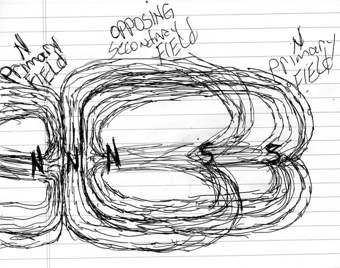
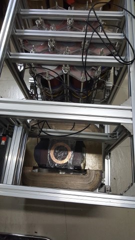
  "1. Winding coils on the primary coil are made on parallel-linked groups to reduce electrical resistance and to react quickly."

EXACTLY, this equates to not only less losses through heat from resistance but as you have observed they will react very quickly to the current changes brought on by part G. part G controls the current flow NOT the primaries so as such they should be wound SPECIFICALLY as electromagnets with as little resistance as possible.

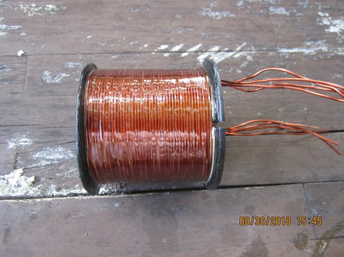
"2. Coil winding to the secondary coil supplying the G-part is winding separately on the secondary."

this can be delt with in various ways so as a precaution i am winding two output coils on the secondary for testing purposes. as i have stated before if part G is plowed full of power the device will surely die and have to be restarted. one must remember that there are three forms or power,  the reducing primary,  the reducing side of part G and the secondary loop back. all three must just add up to the potential drop of the rising side plus the peak of the rising primaries. to much the device dies and to little the device will not self sustain.

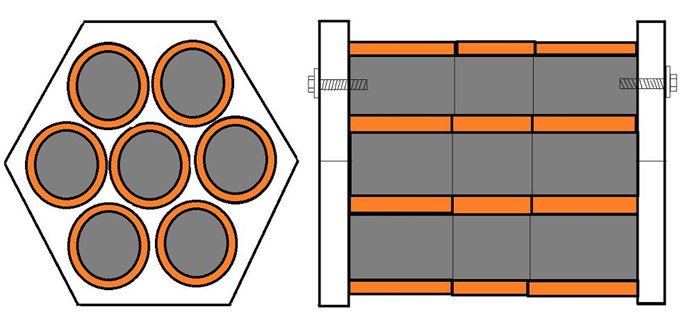
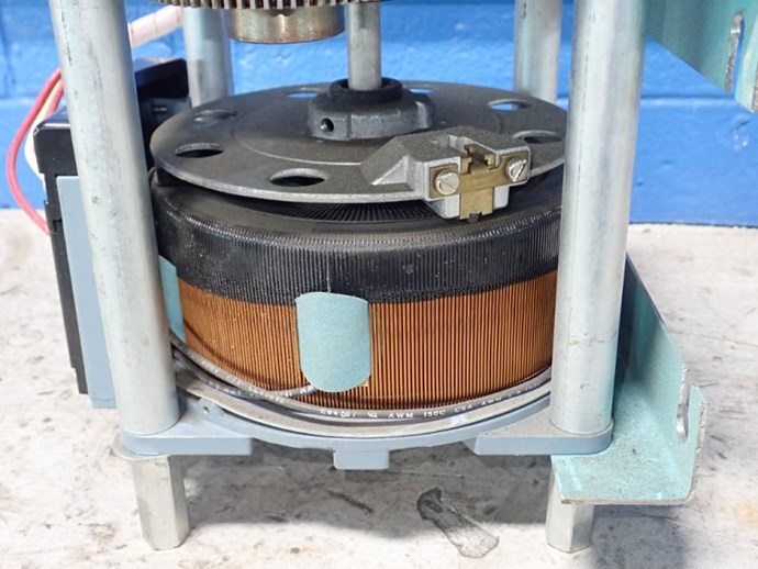
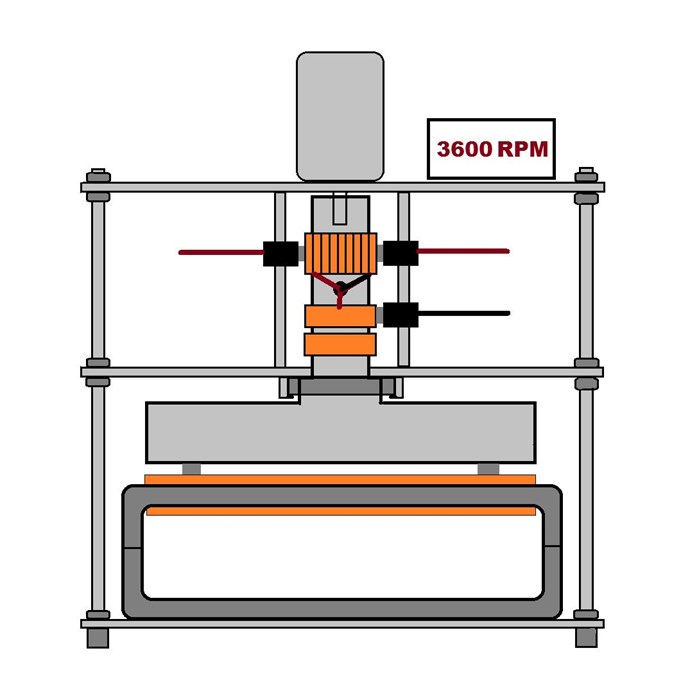
"3. Arrangement of Primary and Secondary Coils sufficiently close enough to benefit from natural ferromagnetic resonance (a very important thing!)."

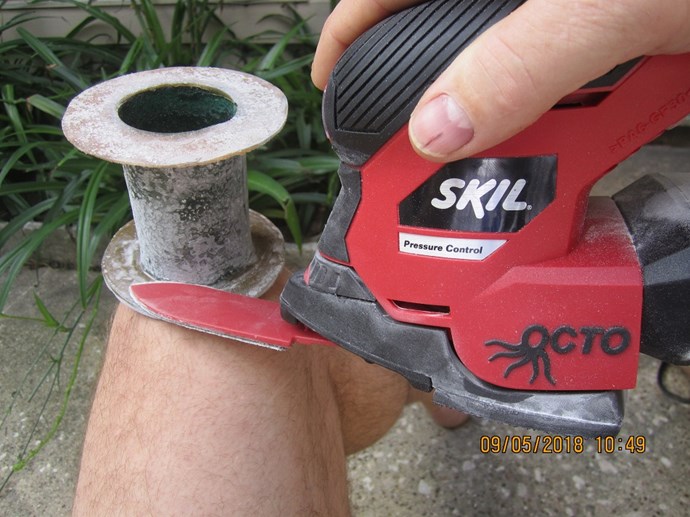
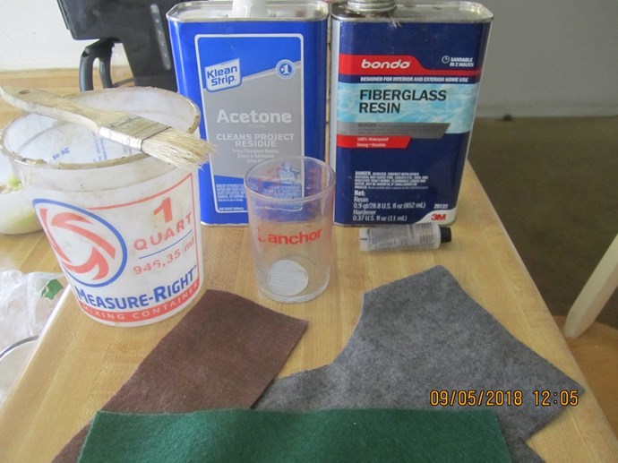
Exactly,  that is why i used resin to attach the cores together. if there was a gap between the cores the flux losses would be to high and the output would suffer substantially. the use of resin or some type of epoxy also has another benefit and that is to stop eddy currants and Hysteresis from the secondary entering the primaries.  this would reduce the effectiveness of the primaries and their sole purpose of being electromagnets with the highest flux possible.

The primaries would be the best electromagnets if using solid cores but the use of laminated for the secondaries is a must as so i have found out. this reduces eddy currents and hysteresis thus increasing the output substantially.

Very good observations.

Regards,

Marathonman


  • Liked by
  • EmilP
  • alohalaoha
Marathonman posted this 05 September 2018

Talk about the right tool for the job. this attachment is so perfect for making of the bobbins. the bobbins are very thin but strong as can be. i think i need  a third hand when doing these shots of my work. this octo from skil came with at least 10 attachments and this one is great for tight spots.

Regards,

Marathonman

Marathonman posted this 05 September 2018

These are the only supplies i need to make my bobbins any size or shape i want. aside from a marker and a pair of scissors. any one of the readers can make your own bobbins whether it be square or round.

Regards,

Marathonman

  • Liked by
  • Vidura
Marathonman posted this 07 September 2018

One must remember that the pressure between your primaries need to be maintained at all times. say i wanted to attain 1 kilowatt output that equates to 14.8 lbs pressure between the primaries at all times which is 7.4 lbs per primary.  now to induce movement into the secondary you have to reduce one primary and increase the other to get the sweeping action across the full length of the secondary. so let say i needed to reduce one primary 30% to get the sweeping action, that will reduce the 7.4 lbs to 5.18 lbs in the reducing primary. that means that the peeking primary must make up the difference to maintain the 14.8 lbs and that will be 9.62 lbs for the peeking primary.

the 14.8 has to be maintained at all times or the output will drop considerably. what most people do not realize is that in order to get that peek at the end of the rising primary the secondary feed back has to be in place. with out this feed back from the secondary there will be no peek at the height of the rising primary thus the output will never attain the 1 kilowatt output or what ever your desired output is.

the reducing primary potential combined with the reducing side of part G will only replace the voltage drop of the rising side of the system. without the secondary loop back the needed peak of the rising primary to maintain the 14.8 lbs will not happen thus the output will be reduced considerably.

Regards,

Marathonman

Marathonman posted this 07 September 2018

ABSOLUTELY FANTASTIC ! an independent Millwright/CNC gut just left the house with my Aluminum plug thus will be finished over the next week or so.

he was referred to me by a company that wanted 600 bucks for the brush holder. (i almost wet my pants) now all i have to do is come up with the money. ha, ha, ha !

it's about time something went my way.

Regards,

Marathonman

Marathonman posted this 09 September 2018

AS soon as i finish my part G i will be releasing a video explaining everything about part G, the why's and how's of the current reduction also the storing and releasing of potential into the system.

for the test set up i will have two light bulbs, one to set N the other to set S for a good visual effect of the synchronous 180 degree current change through the primaries that causes the sine wave secondary output.

this will squash all doubt in peoples minds around the world that an active inductor can and will change current flow in a 180 degree linear fashion.

Regards,

Marathonman

Marathonman posted this 14 September 2018

Sorry folks been out of pocket, had to move.

Regards,

Marathonman

Marathonman posted this 18 September 2018

Sorry for not posting but have been very busy the last few days.dealing with the vet center is as trying as can be as no one gets in a hurry. as soon as i get things squared away i will begin regular posting.

hang in there folks.

Regards,

Marathonman

Marathonman posted this 22 September 2018

Three ways to increase your electromagnet strength and speed of the reaction of the primaries.

  1. Reduce resistance. Self explanatory.
  2. Another way of increasing the current is to use a higher electromotive force, or voltage. The relevant formula is V=IR, the definition of resistance. If V is the drop in electric potential over the entire circuit, and R is the resistance over the entire circuit, the current (I) through any point of the circuit can be increased by an increase in the applied voltage. this is why Figuera used 100 volts and the fact that the secondary feed back to part G with the other added potentials equates to the amplification factor adding to the peak of the rising primaries.
  3. using DC instead of AC. (Self explanatory) the main reason all generators use DC to excite it's electromagnets. AC has to flip all the magnetic domains thus takes a considerable time to do so and will loose induction in the process. thus the reason DC is much more superior in every way and why Figuera used DC in his device.

       Regards.

       Marathonman

  • Liked by
  • Chris
  • EmilP
Marathonman posted this 26 September 2018

Finally my part G is finished so as soon as i pay for it i will post a pic of the finished brush holder. i haven't seen it yet but i am sure it looks awesome.

Regards,

Marathonman

Marathonman posted this 26 September 2018

   I find it funny and some what convenient  that through out all the years of my research not one university anywhere has information on an active inductor. all they describe is a static inductor with changing current and not one single one states that if L changes so does (I) current. they are mutual as either of them changes so does the other.
if I changes so does L but the flip side of the coin that is not published anywhere is that if L changes so does I.  this is the magnetic flux to current ratio and at any given time that the magnetic flux increases or decreases (I) the current flow decreases or increases respectively. as each loop is added or subtracted to either side of the rotating positive brush in part G of Figuera's controller the magnetic flux to current ratio is changing constantly. as each loop is added to that side of the brush the magnetic field around that loop interacts with the loop next to it and it is this interaction that produces an EMF which is in exact accordance with Faraday's LAWS OF INDUCTION and according to the Lenz law this EMF produced within the circuit it's self will oppose the original current flow.

if Figuera had used a standard resistance wire the system would have so much losses through heat that i really doubt the device would ever self sustain. but since he did not use wire resistance  he did not have a heat death device. 
Figuera chose an active inductor for many reasons and one of the main reasons by using a magnetic field to control current flow allowed him to attain efficiencies well beyond that capabilities of resistance wire. using thicker wire on his active inductor Figuera was able to achieve efficiencies in the high 90's with very little core and ohmic losses.
the act of using magnetic flux to control current flow was down right genius on Figuera's part that not only allowed him to store and release potential within the system at specific times but to split the feed into two active circuits controlling current flow of two separate feeds in complete unison.

I salute the sheer genius of Figuera as his device has completely captivated me beyond belief.
even after all this time i still stand in total Awe of Clemente Figuera. 

Regards,
Marathonman

Aetherholic posted this 27 September 2018

A quick update.

All 7 triplets are now wired and mounted, the part G mechanics are assembled and tested, the part G core is wound and polished.

All that is left now is final assembly of the part G mechanics into the frame and completing the wiring.

I still need to design a few laser cut parts for wiring mounting panels and display panels to hold meters and switches.

Once I have been able to test output I can then sort out the power supply for the motor for looped back running.

Aetherholic - One truth, One field

  • Liked by
  • Chris
  • EmilP
Marathonman posted this 27 September 2018

That is outstanding to hear Aetherholic, been running on four to five hours sleep in four days so not much happening on this end. working this weekend will help me in my plight.

I am told things happen for a reason but i am at a loss for words about my situation.

nice build Aetherholic.

Regards,

Marathonman

  • Liked by
  • Chris
  • EmilP
Aetherholic posted this 28 September 2018

Here are some build update pics:

Triplets all finished and wired up

Part G core added

Part G mechanics mounted

Now all that's left to do is final alignment and wiring before further testing.


Aetherholic - One truth, One field

Marathonman posted this 28 September 2018

Outstanding build Aetherholic and i see they are grouped together quite nicely. very good point to bring up as your build is vertical as it can be any orientation the builder likes. i am curious as to the diameter of your brush travel on part G.

very nice build and i love the 3D printed parts.

Regards,

Marathonman

  • Liked by
  • Chris
  • EmilP
Aetherholic posted this 28 September 2018

Marathonman

The brush diameter is about 100mm, The design criteria was to give me 1/4 : 3/4 ratio inductance at the extremes of the travel. This was based on simulation data. Maybe right, maybe wrong so we will see upon first testing. Now just waiting on some more buss bar connectors to arrive then I can start testing. The BDLC motor and driver work great, stable 3000 rpm taking about 70W of power. Waiting for 48 hours for that epoxy to dry and then watching the CNC polishing to see if I got it right was pure torture but the sense of achievement when it worked out ok was pure joy. Thats the great thing about this device, one has to be skilled in so many disciplines to get to a final build. And learning the skills is a great experience. I trashed 30kg of wire during the coil winding process for the triplets. I am sure if I had your patience to hand wind the result would have been much better.

Aetherholic - One truth, One field

  • Liked by
  • Chris
  • EmilP
Marathonman posted this 29 September 2018

yes i agree the self achievement is in a class all it's own. there are a lot of people that cut themselves short in this area staying well within their comfort zone. i on the other hand like to go way out of my comfort zone accomplishing what ever i set my mind to and sharing what i have learned  to others.

I don't have the simulator so i just settled with an adjustable brush holder to accomplish the same thing thus i can use the brush holder with what ever primary to secondary ratio i have at hand all with a slight adjustment.

3.9 is a very good start as the original replicator has about that radius. things are shaping up on my end so i expect to be back in the saddle by the end of next week.

May the Figuera be with you.

Regards,

Marathonman

Aetherholic posted this 30 September 2018

I finished the basic wiring and ran part G for the first time with amperage from an external supply.

After some sparking which required brush pressure adjustment the brush was run at 12 amps with no sparks which gives an average of 6 amps each coil set. The output is a nice clean AC so now I can continue to wire up the commutator and other slip rings.

So far so good. The motor requires slightly more current at the new brush pressure so I measured 100W in, 4W out without any of the other connections so I am happy with this at this point as the primaries need much more current than 6A.

Aetherholic - One truth, One field

  • Liked by
  • Chris
  • EmilP
Chris posted this 30 September 2018

Hey Aetherholic,

If I may say, observe and record the Spark on the Brushes ( Spark Gap ) with all other variables. I believe you will find this to be an important piece as time goes on.

   Chris

Aetherholic posted this 30 September 2018

Chris

With this device sparking is specifically prohibited as it causes field collapse. The DC field needs to be present at all times just like a standard generator and because of the huge inductance when a full set of coils is operating any slight chance to spark causes a huge discharge destroying the DC field. Even at just half an amp the discharge is huge.

Aetherholic - One truth, One field

  • Liked by
  • Chris
  • EmilP
Marathonman posted this 30 September 2018

Chris;


Aetherholic is absolutely correct, there can be no sparking in this device as the magnetic fields set up by the primaries has to be maintained at all times thus when ANY sparking is introduced into the system that means a lack of continuous current flow which equates to a loss of induction.

your perception of this device might not be entirely on solid ground and you might want to reference my posts on the mater. Aetherholic and I are completely on the same page through many Pm's and his knowledge on the subject matter is spot on.

this is the reason for the precision ground surface on part G so there is no sparking of the brushes.

Fantastic catch and assumption of brush pressure Aetherholic, your build is coming along just great,  it is a great pleasure working with someone with not only the build skills but the snap to catch the abnormalties.

Regards,

Marathonman 

  • Liked by
  • Chris
Chris posted this 30 September 2018

Hey Guys,

Of course, I understand what you're saying. However, Brushed Commutators are prone to Sparking, increasing Brush Pleasure on the Commutator will reduce Sparking but also increases required Motor Torque to turn the Shaft at the same speed.

I will leave you in peace now wink

   Chris

Marathonman posted this 30 September 2018

Chris trust me when i say post any darn time you want. i just thought there was certain variances you did not understand and that was my fault.

apologies.

Regards,

Marathonman

  • Liked by
  • Chris
Marathonman posted this 01 October 2018

The original replicator shared some info to me a long time ago and that was buffing or grinding the part G brush surface at the speed the brush rotates. this alleviated all sparking issues and was completely blown away by the lack of brush wear. so to me surface prep is paramount.

Regards,

Marathonman

  • Liked by
  • Chris
  • EmilP
Chris posted this 01 October 2018

Looking forward to seeing your results MM.

I agree a reduction is achievable - However, the Spark could be much more useful than one may be able to imagine: An Impulse Pressure Wave can setup conditions in Coils where it can be very beneficial to the over all outcome!

What year was Clemente Figuera? The Commutators of 1902 no doubt had many more sparking issues compared to our technology today.

All I am pointing out, is, this could be of benefit, Kapanadze's Spark Gaps are critical!

   Chris

  • Liked by
  • Vasile
Vidura posted this 02 October 2018

Chris,

please note that in a commutator there will no spark occur, it is likely to be arcing, and won't produce a disruptive discharge.

in what i am agreed is that probably a hounded years ago the accuracy if machining was not the same like today.

  • Liked by
  • Chris
Chris posted this 02 October 2018

Hey Vidura,

Apologies, yes, Spark = Arcing, this is what I meant. An Arching is a Spark of sorts.

Apologies, Builders please continue, I have nothing more.

   Chris

  • Liked by
  • Vasile
Marathonman posted this 02 October 2018

You have to realize that Figuera more than likely use Zeiss to manufacture the core and they were absolute precision devices for sure. if you look at the circle at the top of Zeiss you will be quite surprised at the level of genius.

Sorry, no sparking allowed and i beg to differ, the machining back then was quite amasing.

Regards,

Marathonman

  • Liked by
  • Chris
  • EmilP
Marathonman posted this 06 October 2018

 I have some bad news, the day before yesterday i got a very bad phone call. it seems my sorry ex room mate let a drug addict into the house by herself and she and another person destroyed my locked door to my room where all my stuff was being stored until i get back on my feet. they took 2,400 dollars worth of stuff including all my primaries and secondaries. all my wire is gone including all my hand tools, TV camping equipment, mongoose bicycle and loads of other stuff. i filed a police report and sought legal counsel to sue not only the drug addict but also my sorry pathetic alcoholic ex room mate that let her in.

I have nothing to build with as i lost everything so i must gracefully bow out at this time as i can no longer build a thing until i get on my feet. in the next few weeks when i get back on my feet i will pick up where i left off but until then i will be in contact with Aetherholic as a technical advisor only.

regards,

Marathonman

Vidura posted this 06 October 2018

Hey Marathon Man, I'm really sorry about that strikes you suffered, and hopefully you can recover soon or get back your stuff. As I am not that wealthy I can't offer helping with money, but let me tell you that I wish you to have success, and admire your persistent work on the figuera device, your sharing of information, and would be happy to see your work to be concluded .Regards Vidura.

Aetherholic posted this 06 October 2018

Marathonman

I think we are all sorry to hear this news, no one should have to suffer this especially when they are so close to a working device and have shared so much. I am continuing the build so hopefully we can bring Figuera to life at last one way or another.

Never give up, never surrender.

Aetherholic - One truth, One field

  • Liked by
  • Chris
  • EmilP
EmilP posted this 07 October 2018

Marathonman

I'm sorry to hear what happened to all your goods. If you stay as a technical consultant for the moment, it is a great win for this forum. We will follow Aetherholic who is a very competent manufacturer and technical artist.   All the best. EmilP

  • Liked by
  • Chris
Marathonman posted this 07 October 2018

Even though it is very painful to watch someone else finish my work i am still quite grateful that my knowledge and sharing of this device is coming full circle through Aetherholic. even though i was right about the loop back we have shared a lot in the last few months so much so that he will have a working device very soon. his knowledge in the simulations on his part literally verified everything of the loop back feature i had suspected that allows the device to not only sustain it's self but to give the primaries the added peak at the right moment maintaining the required pressure between the primaries.

I thank you all for the kind comments and i most certainly am very grateful for having the opportunity to share with everyone around the world as this was my only goal to help humanity take a new road to travel.

i will be back on my feet soon.

I would personally like to thank the original replicator for sharing some very valuable information to me  as none of this would have been possible if not for the path for which to travel on. of course the ball busting last 5 or 6 years of study and bench work sure did help to.

i would also like to thank all the trolls for busting my ass and making me mad enough to not give up and to shove the truth up their back side. ha, ha, ha !

Thanks !

Regards,

Marathonman

Topic Is Locked

We're Light Years Ahead!
Members Online:

No one online at the moment


What is a Scalar:

In physics, scalars are physical quantities that are unaffected by changes to a vector space basis. Scalars are often accompanied by units of measurement, as in "10 cm". Examples of scalar quantities are mass, distance, charge, volume, time, speed, and the magnitude of physical vectors in general.

You need to forget the Non-Sense that some spout with out knowing the actual Definition of the word Scalar! Some people talk absolute Bull Sh*t!

The pressure P in the formula P = pgh, pgh is a scalar that tells you the amount of this squashing force per unit area in a fluid.

A Scalar, having both direction and magnitude, can be anything! The Magnetic Field, a Charge moving, yet some Numb Nuts think it means Magic Science!

Message from God:

Hello my children. This is Yahweh, the one true Lord. You have found creation's secret. Now share it peacefully with the world.

Ref: Message from God written inside the Human Genome

God be in my head, and in my thinking.

God be in my eyes, and in my looking.

God be in my mouth, and in my speaking.

Oh, God be in my heart, and in my understanding.

Your Support:

More than anything else, your contributions to this forum are most important! We are trying to actively get all visitors involved, but we do only have a few main contributors, which are very much appreciated! If you would like to see more pages with more detailed experiments and answers, perhaps a contribution of another type maybe possible:

PayPal De-Platformed me!

They REFUSE to tell me why!

We now use Wise!

Donate
Use E-Mail: Chris at aboveunity.com

The content I am sharing is not only unique, but is changing the world as we know it! Please Support Us!

Thank You So Much!

Weeks High Earners:
The great Nikola Tesla:

Ere many generations pass, our machinery will be driven by a power obtainable at any point of the universe. This idea is not novel. Men have been led to it long ago by instinct or reason. It has been expressed in many ways, and in many places, in the history of old and new. We find it in the delightful myth of Antheus, who drives power from the earth; we find it among the subtle speculations of one of your splendid mathematicians, and in many hints and statements of thinkers of the present time. Throughout space there is energy. Is this energy static or kinetic? If static, our hopes are in vain; if kinetic - and this we know it is for certain - then it is a mere question of time when men will succeed in attaching their machinery to the very wheelwork of nature.

Experiments With Alternate Currents Of High Potential And High Frequency (February 1892).

Close