Clemente Figuera

  • Topic Is Locked
  • 49K Views
  • Last Post 16 July 2019
Wistiti posted this 09 January 2018


Hi guys!

In the past I play a bit with the Figuera concept. It use the POC as we already know the potential. I think this guy, Marathonman, understand the principe behind the Figuera device...

Chris, if there already a tread about Clemente Figuera, feel free to move this at the good place!


Order By: Standard | Newest | Votes
Marathonman posted this 07 January 2019

Alset;

  The force of 1000 turns will be much higher then that of 100 turns but it still reduces by the square of the distance. a three inch core with 1000 winds will project at most when saturated to 3.2 to 3.3 inches which is still not enough pressure at 3 inches to amount to squat output. Now increase the core length to 6 inches and watch the output go through the roof, thus your oyster will open.

Regards,

Marathonman

romanta posted this 11 January 2019

in my free time I am engaged in preparing for the manufacture of a small device.

Cornboy posted this 12 January 2019

 Great Work Romanta.

 Regards  Cornboy.   smile

Marathonman posted this 12 January 2019

Yes great work and those bobbins look home made..... Brovo! Just remember to make your primaries twice as large as your secondaries and your oyster will open freely.

Regards,

Marathonman

Marathonman posted this 12 January 2019

Members, builders and readers please do tests on your magnets and electromagnets to verify what i have been trying to convey to you that a magnetic field will only project out the actual lengrh of the core from whence it was born. Once you do this you will see why i said 2 to 1 ratio.

Regards,

Marathonman

  • Liked by
  • Chris
  • Cornboy
Marathonman posted this 13 January 2019

When you retract a magnetic field in the space occupied by the secondary you cause a circular electric field around the secondary at that very moment your increasing electromagnet is occupying the same space producing another electric field that is superimposed over the top of the first electric field. Since both electric fields are positive, additive and in the same direction you get an increase in output that matches that of a standard generators high intensity field that utilizes both poles. Figuera device is a Duel Mono-Pole Excitation System that compresses the field lines to match that of a standard generator.

It's that simple.

Regards,

Marathonman

Marathonman posted this 14 January 2019

NEW INFORMATION.

   In the standard model of inductive reactance you have the (cause) a current change and an ( effect) an inductance change that is taught around the world in every college. since i have basically proven that inductance can control current flow as well as current flow controlling inductance. In the Figuera device we have just that inductance controlling current flow but with an added twist on the old model. I have come to realize that in part G we have not only inductance but inductive reactance except in this case inductance is the (cause) and current flow change is the (effect).  since they are interchangeable Inductive reactance in the Figuera device is  Caused by inductance and the current change is the effects of it's change. It is still inductive reactance while using DC, rotating a brush to give it frequency.

XL= 2P X F X L

XL= inductive reactance measured in ohms.

2 = a constant 2 X P, (3.1416) = 6.28

F = the AC frequency of the supply but in this case of DC it is the brush speed which gives the frequency at 60 hertz 3600 rpm 50 hertz 3000 rpm all others.

L = the inductance of the coil on part G's core.

Example;

Part G positive brush at set N side measured at set S 0.2 henries inductance.

6.28 X 60 Hertz X .0.2 heneries is 75.36 ohms.

120 volts excitation / 75.36 = 1.59 amps of current flow on the low side of set N.

Set N measured at it's highest potential gives 0.15 henries inductance.

6.28 X 60 hertz X 0.15 henries = 56.52 ohms.

120 volt / 56.52 ohms = 2.12 amps of current flow when set N is high.

These calculations are will help you calculate part G's inductance and currents running through it. 120 volt is just an example as mine i will have 100 volts.

Regards,

Marathonman

alset posted this 15 January 2019

Aetherholic,

Could you give us some tips based on your experience about how we should build this generator? Some ideas about things to do or to avoid?

Grateful for all info. Thanks in advance.

  • Liked by
  • Vidura
  • Chris
Marathonman posted this 15 January 2019

Sorry for all the mistakes in my postings. using a cell phone to post is a royal pain. all posting over the last few days were corrected and are much more understandable and in better format thanks to the use of a computer.


Newton's law of universal gravitation follows an inverse-square law, as do the effects of electric, magnetic, light, sound, and radiation phenomena.

It is also a fading of the distance and mathematical to the source.

The inverse-square law generally applies when some force, energy, or other conserved quantity is evenly radiated outward from a point source in three-dimensional space. Since the surface area of a sphere (which is 4πr2&nbsp is proportional to the square of the radius, as the emitted radiation gets farther from the source, it is spread out over an area that is increasing in proportion to the square of the distance from the source. Hence, the intensity of radiation passing through any unit area (directly facing the point source) is inversely proportional to the square of the distance from the point source. Gauss's law is similarly applicable, and can be used with any physical quantity that acts in accordance with the inverse-square relationship.

The Iron core creates an easier path for flux to travel but it does NOT stop the Square of the distance.

I rest my case pertaining to the magnetic fields,  Figuera's electromagnets and the Inverse Square Law.

Regards,

Marathonman

Aetherholic posted this 15 January 2019

alset

There is no blueprint for this device yet so my advice is do what I did first and spend time reading each and every post on this and other forums to see where successes and failures have been, work out why and then use this in your design. My tips at this particular moment in time would be dont use tesla winding as its not necessary, make sure you calculate the force on the brush due to rotation so it wont stick in the holder, use a c type core for part G, do hundreds of experiments to understand how the device is operating,

These tips are not gospel and may change so until we are at the stage where an idiots guide to building a working system is available everything is subject to change. I am trying to limit my posts to things which i know for certain are correct.

Aetherholic - One truth, One field

alset posted this 15 January 2019

Aetherholic,

Thank you for your kind answer. Just one last question: What is your opinion about firing the part G with MOSFETs instead of doing it with a rotating brush , which is really very difficult to build properly? Maybe 20 MOSFETs to emulate the whole circle of the brush, so a connection every few turns. I mean leaving direct connection between each set of electromagnets using the part G winding and just injecting the fresh current with electronics. How many turns did you used in your part G?

Thanks and good luck!

Aetherholic posted this 15 January 2019

alset,

There has been some discussion before about a solid state solution and i have yet to see a design that can perform the same as a brush version, you would need a mosfet for every turn that the brush would normally be in contact with  to do it correctly. My part G has 93 turns.

Aetherholic - One truth, One field

romanta posted this 16 January 2019

I greet you on this thread of the forum.
I made 6 primary coils and 2 of which I connected a push pool to the generator.
"important note" !!!! never use a switch on transistors to power such coils on a full iron core, this will lead you to the likelihood of fire due to overheating of the core !!!
The winding of the primary coils was 4 layers of 37 turns of wire of 1 mm diameter.
The magnetic field created by this coil with a core, in my opinion, is not strong enough for good operation of the device. I will add 2 more layers of winding. The current supply device of one triad 14 volts and 3 amps. I proceed to the manufacture of secondary coils and reactor G.


Vasile posted this 16 January 2019

I like your build so far. Hope to see it complete soon.

All the best!

Cornboy posted this 16 January 2019

Great job Romanta, thanks for sharing.

 Best Regards,  Cornboy.   smile

Cornboy posted this 16 January 2019

alset

There is no blueprint for this device yet so my advice is do what I did first and spend time reading each and every post on this and other forums to see where successes and failures have been, work out why and then use this in your design. My tips at this particular moment in time would be dont use tesla winding as its not necessary, make sure you calculate the force on the brush due to rotation so it wont stick in the holder, use a c type core for part G, do hundreds of experiments to understand how the device is operating,

These tips are not gospel and may change so until we are at the stage where an idiots guide to building a working system is available everything is subject to change. I am trying to limit my posts to things which i know for certain are correct.


 Aetherholic, your tips obviously come from practical experimenting, Thanks.


 As i will soon have a go at winding 5 sets of primaries, what would you suggest as the best winding method, and how much DC resistance is acceptable for a primary coil.


 Regards  Cornboy.  smile

  • Liked by
  • Vidura
  • Chris
Aetherholic posted this 17 January 2019

Cornboy

There are different ideas for the functioning of this device which will result in different needs for coil sizes. I cant give you a definitive answer yet but obviously what you must make sure of is that the output is able to generate enough amps and volts to power the field. Too high resistance or too low resistance will result in not being able to self excite. The other problem is that one set, two sets or a full number of sets will give you different results due to field interactions between the sets, some of benefit, some not, so the whole array arrangement is important.

I had hoped to have moved faster with the build but I have had a months delay so hopefully I will have more information soon. Dont rely on anything 100%, please do experiments to verify what you are building.

What i can say is that the final system is so close I can taste the OU, I have it in the system and with a non figuerra configuration so its all a question of balance. You will see it in various parts of your system as you progress.

I have absolutely no doubt that there will be success.

Aetherholic - One truth, One field

  • Liked by
  • Chris
  • Vidura
romanta posted this 17 January 2019

I deviate a little from the original design, and try to clarify the situation with the power supply of the primary coils for the test, without using the "G" reactor.
Based on what I saw and read within this branch, I realized that to power the primary cores, it is necessary to use the pulsating DC component of the current, the only electrical part that can replace the core "G" to some extent with the test time, this is PWM current adjustment . If anyone can write a program for such regulation, I will be very grateful

. 

The graph in the picture does not accurately display the necessary parameters, but I think the point is clear. Thus, we will not lose the extra current for heating the resistors.


Regards Romanta

Zanzal posted this 17 January 2019

I deviate a little from the original design, and try to clarify the situation with the power supply of the primary coils for the test, without using the "G" reactor.

If you want to do something like this you may find it simpler to use a two channel arbitrary waveform generator. Using one of these you can custom wave form that has the voltage curve you are after and run both channels at the same frequency 180 degrees out of phase. This has the benefit of allowing you to customize the output and try different wave forms. If I understand the principles behind Figuera you should not allow the voltage on either side to ever drop to zero so there should be a DC offset, but you can try it and see how it works.

Marathonman posted this 18 January 2019

Exactly Zanzal,, the primaries are only reduced to get the seeping action across the entire secondary then back to full potential. This creates two electric fields superimposed over the top of each other along with the other reasons i had mentioned for the reduction of the primaries. If the primaries are taken down to far induction will fail as the coherency between the primaries is lost.

Regards,

Marathonman

romanta posted this 18 January 2019

I apologize for not understanding each other.
Since you looked at the picture, and probably did not perceive the written words through a translator.
With the help of STM32 programming, any current control signal can be achieved. even this one.


  • Liked by
  • Chris
Marathonman posted this 18 January 2019

If you can control the current of two different outputs 180 out from one another you will be in the ball park. But one has to remember electronics can not add back into the system like a reducing inductor feeding the increasing side. When the reducing side is reducing it releases the reduction in the form of potential off setting the voltage drop of the rising side. Part G has to be in the system with electronics switxhing the contacts.

On a sad note i got my bench back together but sadly mt ex room mate threw 850 bucjs worth of cores in the trash just to spite me so i literally have nothing to work with at this moment.

Good luck.

Regards,

Marathonman

  • Liked by
  • Chris
Marathonman posted this 22 January 2019

On a very good note i have figured out how to switch part G with electronics exactly mimicking the brush rotation to a T but the amazing part is that will include the negative brush from the secondary feed back. Each start of the sigal run will be at opposite ends of the inductor but will be switched by the same signal generator at 60 or 50 cycles a second.

I will be discussing this with other members first before i present this proposal. This will make the Figuera device totally non moving but with the added expenses of electronics.

Regards,

Marathonman

alset posted this 22 January 2019


Hi again, A contact every 5 turns will give a little sharper signal but the function is the same as a contact per turn.

I could say that a contact per turn is still to sharp to run and that you should touch a wire going along all its perimeter in each turn to get a really smooth signal. But this has no sense.

If a contact per turn works I hope that a contact per 5-6 turns should work either.

Thanks!

Marathonman posted this 22 January 2019

That will definitely be something that has to be tested. Per turn contact as with the brush gives a very linier rise and fall of current.

I personally will be sticking to mechanical device but will be giving others additional options.

Regards,

Marathonman

  • Liked by
  • Vasile
  • Aetherholic
Marathonman posted this 22 January 2019

Good news everyone I just got hired and start Friday, give me a few weeks and let the building begin.

Regards,

Marathonman

alset posted this 23 January 2019

Congratulations!!

One question about the part G design: How many brushes are required? I suppose that just one brush is required, to mimick the patent design contacting with the resistance. But in one of the last post I understood that more than one brush is required...

I am fan of electronic switch and the number of contact points must mimick the movement of the brush. Thus why I want to clarify this point.

Marathonman posted this 23 January 2019

Alset;


  The secondary loop back is and was the last piece of the puzzle to be solved. in the patent Figuera states a brush or group of brushes and sense part G becomes the power supply when the starting is removed then the secondary must be injected into part G.

with a second brush the secondary feed back can be ran through a commutator thus the positive side can be connected to the positive brush and the negative side can be attached to the second brush adding additional flux to the reducing primaries and the reducing side of part G thus giving the rising primaries an added boost at it's peak to replace the 30 % reducing primaries to get the sweeping action across the secondary.

the reducing side of the device will release it's reduced magnetic field into the system to off set the potential drop of the rising side of the system and the secondary is there to replace looses occurred and to give rise to amplification to the rising primaries.

if you are in the replication process please build your primaries no less then a 2 to 1 ratio at minimum that was the magnetic fields of the primaries can hit the needed pressure for the output.

The electronic switching i came up with will in fact mimic both brushes switching in opposite direction from the same signal generator on top of the inductor. the Figuera device CAN NOT OPERATE without the inductor so without it no self operation will exist.

Thank you very much. i have taken one hell of a beating in the last year but Marathonman is one hell of a trouper and will bounce back stronger then EVER !

Regards,

Marathonman

alset posted this 24 January 2019

Sorry, but I do not understand your point. If you connect the positive and negative of the battery to the part G then you will be shortcircuiting the electromagnets. Maybe I interpreted it wrong. In the patent just the positive is connected the the rotating switch.


Could you provide an schematic of all the connections of part G and the electromagnets?


Aetherholic, Did you use one or two brushes in your part G?


Thanks and sorry if I misunderstood anything.


  • Liked by
  • Chris
  • Vidura
Marathonman posted this 24 January 2019

NO, it is adding to the magnetic field of part G and becomes a separate energy quanta from the current that created it, it then will circulate throughout the system.  as i said the patent even states a brush or group of brushes and confirms there is a switch which is a commutator in reality changing AC from the secondary to DC through the commutator.

my computer is not on line yet as i still need a monitor. i will post a schematic when i can.

Regards,

Marathonman

Aetherholic posted this 25 January 2019

alset

I have one brush operating at the moment but I have the second brush available to use.

Aetherholic - One truth, One field

  • Liked by
  • Chris
  • Vidura
alset posted this 25 January 2019

Thanks for your answers.

The simpler the better (KISS phylosophy), and matching with the patent even better!

Thanks.

  • Liked by
  • Chris
  • Vidura
Marathonman posted this 28 January 2019

The patent says brush or Group of brushes, imagine that.

Marathonman

  • Liked by
  • Chris
  • Vidura
alset posted this 28 January 2019

The secondary output is AC. It can not used directly as feedback to the primaries unless you convert it to DC. Imagine that too.


If you read Buforn patents you will note that he used two secondaries: one for net output power and , another , smaller, to be converted to DC and used as feedback.

  • Liked by
  • Chris
  • Vidura
Marathonman posted this 29 January 2019

Alset:

I am sure Glad you shared that with me as i never would of figured that out by myself.

i have been pursuing this device for 6 years and can probably quote every word in the patent and i care not mix words with you.  i am well aware of the secondary feed back that is commutated then feed into part G. yes Buforn did mention a secondary which is viable option or even a dedicated secondary but you have to remember Buforn was NOT a Physics Professor like Figuera was as he was just a financial backer. yes he did add a few more bread crumbs but them again he was just a financial backer and his subsequent patents were actually null and void as they infringed on the 1908 patent.

If you actually read this thread in it's entirety you will learn what you are mentioning was shared quite a long time ago by myself and it is not I that needs to catch up to present day mind set thank you.

Regards,

Marathonman

  • Liked by
  • Vidura
  • Chris
romanta posted this 03 February 2019

I propose a method of winding and manufacturing of primary and secondary coils. As shown by practical application, with this type of wire winding, the inductance of the solenoid is very close to zero. When the inductance is very small, then the level of the back EMF is very small, and the strength of the two solenoids is added.

With respect, Romanta

Marathonman posted this 03 February 2019

romanta,

   I personally think one should try to build the original (1908 Patent) which is what this thread is following and get it working before one decides to start making changes to the original design. by building the original design one will there four understand all that is happening in the device, acquire a deep understanding of each piece and the field interactions. once this understanding of the device is achieved one can then make changes to the device to suit ones needs.

good luck just the same.

on a good note this is my first post from my own apartment. i just fired up my computer for the first time in five months and man it sure is nice using a good fast computer for a change.  library computers or cell phone suck big time compared to a 3960E processor, 16 Gig of memory and a Kingston Hyper X SSD all planted on a Gigabyte mother board. BOO YA !

Marathonman

Peter posted this 04 February 2019

Hey Marathonman,


Very good to hear you're back up and running....

I think more people will call upon your unique understanding of the figuera device, once more of us get close to finishing it.

So nice to know you're connected again.

Happy building.

Kind regards,


Peter


Marathonman posted this 05 February 2019

And i will gladly be here Peter to aide any and all.

Thank you kindly.

getting bids on core material as we speak from Bridgeport Magnetic's and Temple Transformer.

Marathonman

  • Liked by
  • Cornboy
  • Chris
Cornboy posted this 09 February 2019

 Hi All, finally had some time to work on my new rotary internal commutator, next onto building 5x sets of triplets.


 Regards  Cornboy.   smile

Vidura posted this 09 February 2019

Hey Cornboy, Nice built your commutator, if I may suggest build first one set of triplets and do some testing, good luck!

Cornboy posted this 09 February 2019

Thanks Vidura, good advice, will do.


 Regards  Cornboy.  smile

  • Liked by
  • Vidura
Marathonman posted this 09 February 2019

Good to see someone has the time to build. yes that was good advice and remember the 2 to 1 ratio on those cores. what are the parameters of your part G.

Finally after all these months in purgatory i was able to pay for the brush holder. here it is not put together just yet with the motor sitting on top. the brushes that rotate on part G will be mounted in the slots that can be adjusted to get my desired current window of high and low. the hole in the side is for the wire from the slip ring and the commutator  through the shaft as it to is drilled out. the wires to the brush has a hole drilled out in the slots to the center shaft hole to connect to each other.

Simply lovely if i say so myself.


Regards,

Marathonman

Cornboy posted this 10 February 2019


 Hi MM, and all, my part G, is simply a rotary switch, my cores are part R they consist of 54x 1.6mm copper coated welding rods, with a 1.2mm copper single winding 240mm long.

 The combined core mass of the 13 inductive resistor bars is 2.6 kg.

 I am trying to replicate the 1908 patent Sketch, as i see it, understanding it is only literally a thumb nail dipped in Tar, sketch.


 Warm Regards  Cornboy.  smile


Marathonman posted this 10 February 2019

"understanding it is only literally a thumb nail dipped in Tar, sketch."

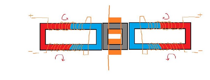
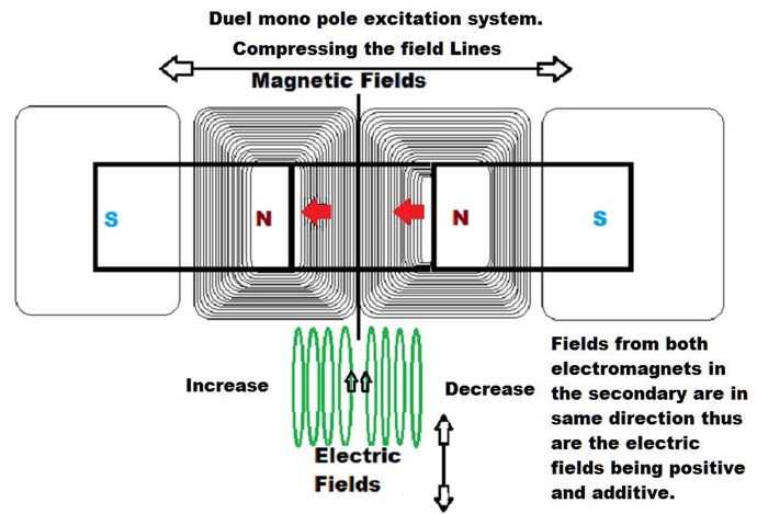
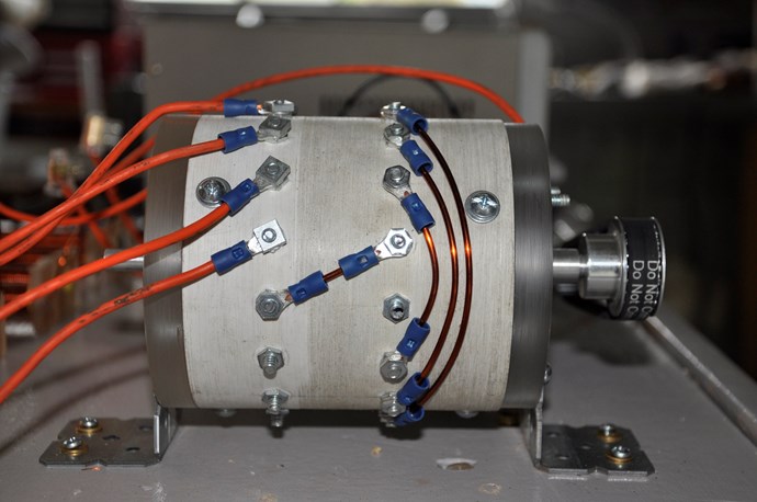
exactly so why try to replicate something that literally does NOT exist ?   Figuera was describing his part G in half quadrants  ie. the first semi circle and the second semi circle which is literally the travel of the brush in a circle on his closed core part G. the commutator bars he was describing were actually the winding's on his closed core part G so therefore it would be an active inductor with a moving positive brush that changes the magnetic flux to current ratio on a steady basis.

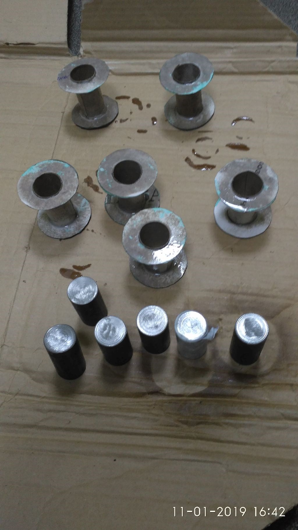
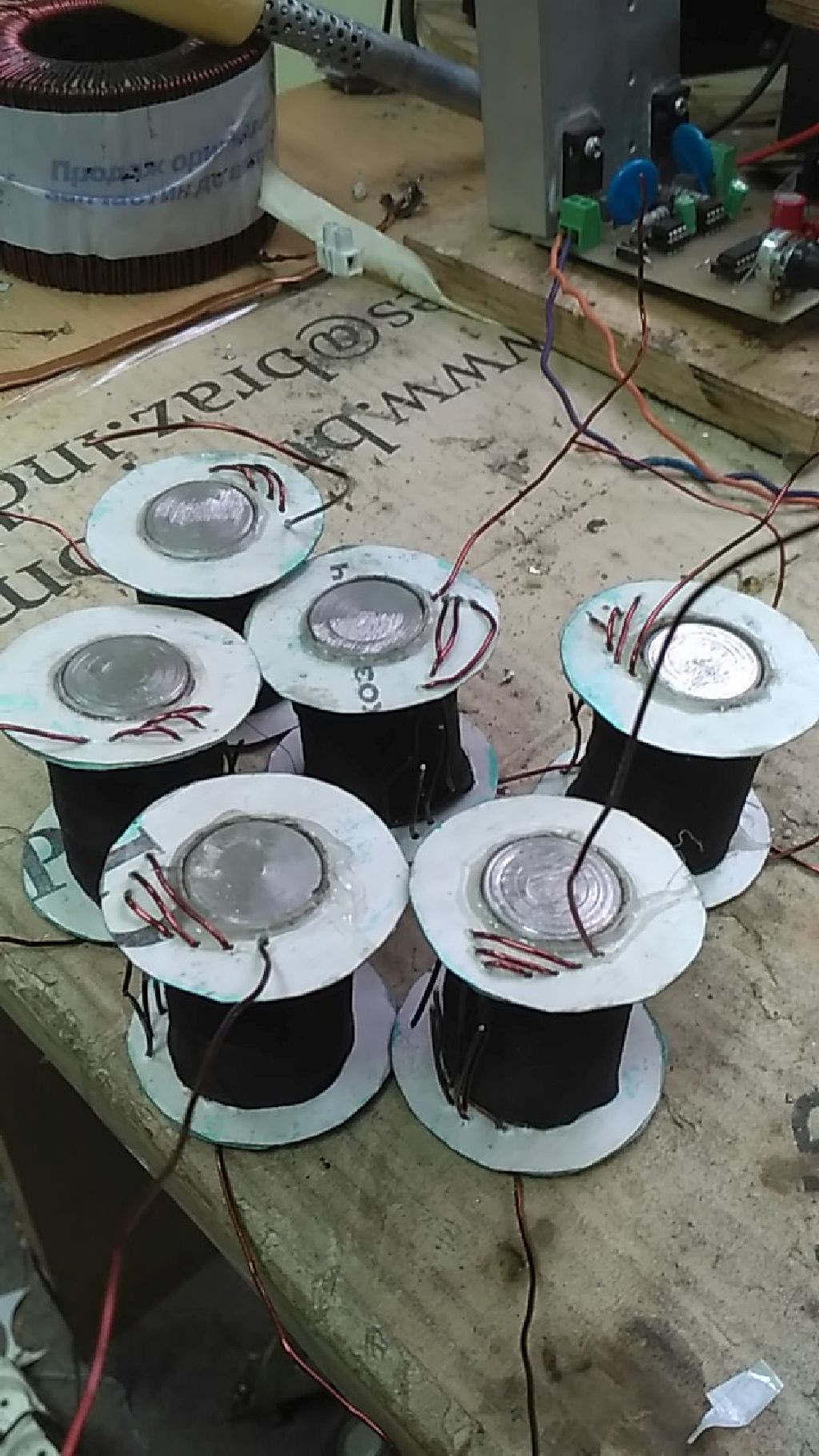
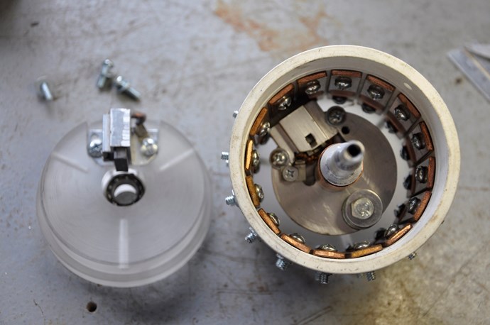
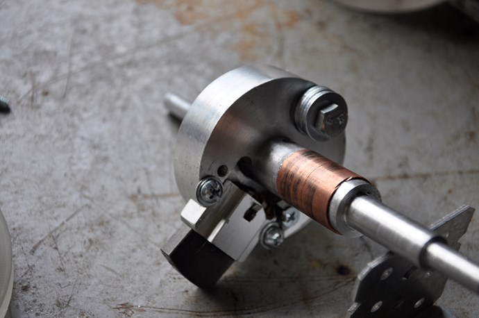
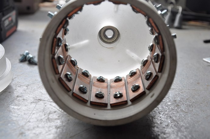
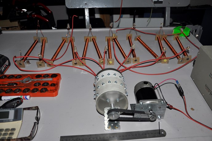
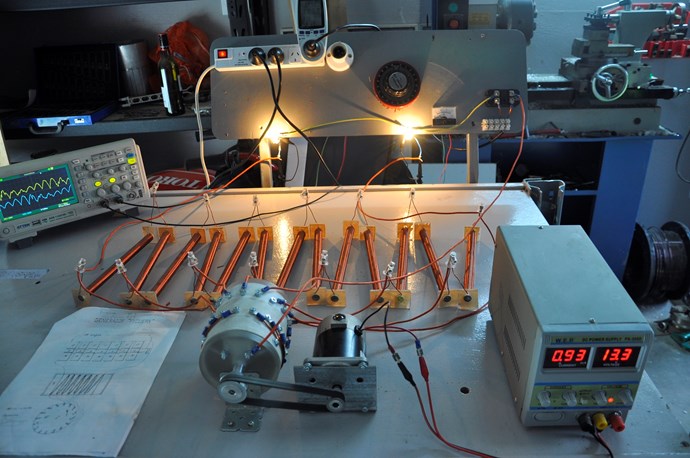
but since you used your god given brain, you have inductive rods NOT resistance so your device just might work and i commend you on your build skills. each rod will induce a certain amount or self inductance as per the brush rotation.....very ingenious . just make sure you have the correct inductance as per your current needed and remember he was using a closed core preserving the flux in the core but in your case you have an open core so the cores will have to be much larger to account for the massive flux loss.

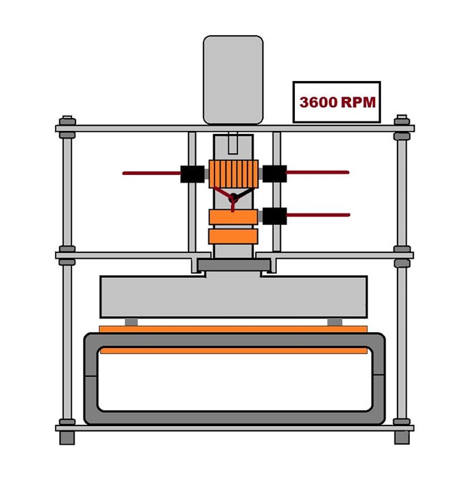
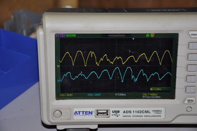
Figuera is literally taking DC and giving it Frequency by changing the magnetic flux to current ratio as the brush rotates causing the current flow to increase and decrease which gives it Frequency which will then be INDUCTIVE REACTANCE having AC like qualities but with none of the AC limitations.  with AC we will have to flip the domains in the core which can not be done fast enough in this device so he used DC and just increased and decreased the current flow which gave it AC like qualities...ie inductive reactance

since inductance and current Change go hand in hand each can be the initiator in inductive reactance.  a current change (cause) can cause a change in inductance (effect) as well as a change in inductance (cause) can cause a current change (effect) it is still inductive reactance just initiated by inductance.

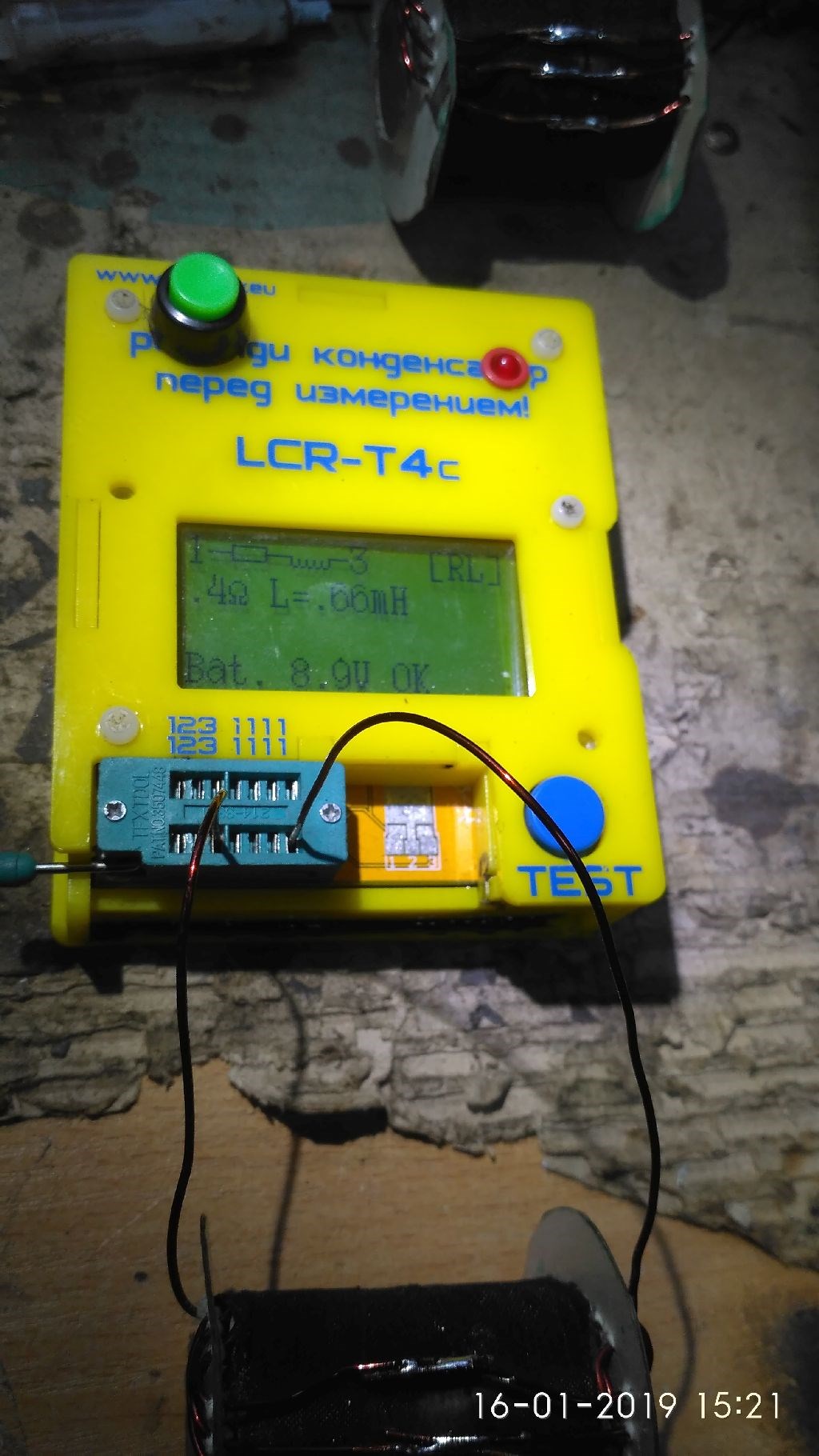
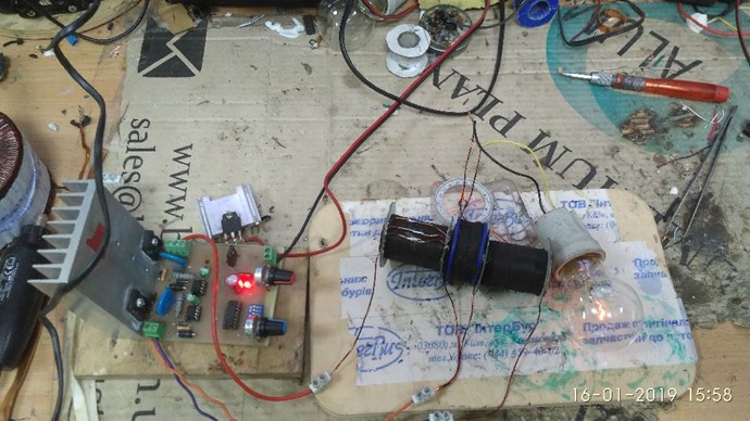
inductive reactance, or X L, is the product of 2 times p (pi), or 6.28, the frequency of the ac current, in hertz, and the inductance of the coil, in henries.. X L =2 p x f x L so use this to calculate your current window and you will be just fine remembering to account for your flux losses in your cores and 50 hertz of your country.

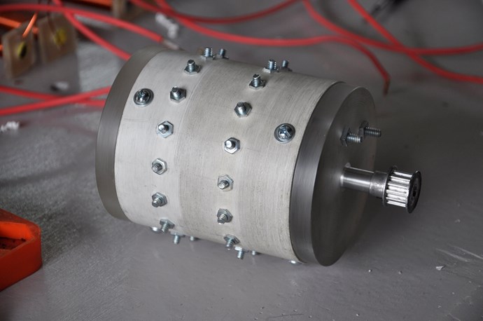
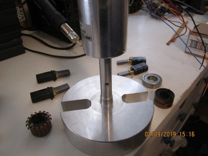
excellent build skills Cornboy, i see you accounted for the rotational mass and balanced it...... very nice indeed.

Regards,

Marathonman

  • Liked by
  • Vidura
Cornboy posted this 10 February 2019

 Thanks MM, i think.

 I am well aware of what you have been trying to teach, after all, i have been on the Figuera device for a few years now, with UFO, and yourself.

 I am determined to go this path to prove for Myself, that i can stick to one path, and see it to completion, and not keep chopping and changing, also i have limited budget for the next couple of years, starting a new farm from scratch at 65 is not easy, and i am using what i have on hand.

 Please prove me wrong and build a working device based on your teachings, and i will drop everything, even borrow funds, and follow exactly your build.

 Regards  Cornboy  smile

  • Liked by
  • Vidura
  • Vasile
Marathonman posted this 11 February 2019

I am not asking to drop everything, i am just trying to get you to understand the flux losses in an open core part G. i ment no disrespect what so ever and actually gave you multiple compliments on your build skills.. 

have you tested your rods self inductance.?

Regards,

Marathonman

Marathonman posted this 13 February 2019

Base plates are ordered for my part G from on line metals dot com,  top, middle and lower plate that i will attach most everything to. ordered two different brushes as i noticed the tabs are in the wrong spot and have some threaded rod coming also.  person that worked on the brush holder bent the upper shaft but it is not a problem as i can straighten it out.

2.25 inch square cores 6 inch and 3 inch will be on order in the next few days as will the C core that got trashed by ex so called friends. the cores are coming from Temple Transformer and the C is coming from Bridgeport Magnetics that made my last flawless C core.

below is a representation of what i am trying to accomplish in this controller build part G.

Man it sure is nice making good money again.


Regards,

Marathonman

Marathonman posted this 13 February 2019

This graph is food for thought thus what is taking place in the Figuera device.

Regards,

Marathonman

  • Liked by
  • Vasile
Cornboy posted this 13 February 2019

 Hi MM and all, it was so stinking hot here today, i stayed indoors and got to work on my device.

 Is this the wave form we are looking for to drive the inducers? or have i wired it up wrong?

 I must admit i am a scope dummy.

 I have opted for a variac inverted to dc, to start the device, as adjustability will be great.

 This is just testing with 2x24v 70w light bulbs to view the waveform of my new part G.

 Regards  Cornboy.  smile


Topic Is Locked

We're Light Years Ahead!
Members Online:

No one online at the moment


What is a Scalar:

In physics, scalars are physical quantities that are unaffected by changes to a vector space basis. Scalars are often accompanied by units of measurement, as in "10 cm". Examples of scalar quantities are mass, distance, charge, volume, time, speed, and the magnitude of physical vectors in general.

You need to forget the Non-Sense that some spout with out knowing the actual Definition of the word Scalar! Some people talk absolute Bull Sh*t!

The pressure P in the formula P = pgh, pgh is a scalar that tells you the amount of this squashing force per unit area in a fluid.

A Scalar, having both direction and magnitude, can be anything! The Magnetic Field, a Charge moving, yet some Numb Nuts think it means Magic Science!

Message from God:

Hello my children. This is Yahweh, the one true Lord. You have found creation's secret. Now share it peacefully with the world.

Ref: Message from God written inside the Human Genome

God be in my head, and in my thinking.

God be in my eyes, and in my looking.

God be in my mouth, and in my speaking.

Oh, God be in my heart, and in my understanding.

Your Support:

More than anything else, your contributions to this forum are most important! We are trying to actively get all visitors involved, but we do only have a few main contributors, which are very much appreciated! If you would like to see more pages with more detailed experiments and answers, perhaps a contribution of another type maybe possible:

PayPal De-Platformed me!

They REFUSE to tell me why!

We now use Wise!

Donate
Use E-Mail: Chris at aboveunity.com

The content I am sharing is not only unique, but is changing the world as we know it! Please Support Us!

Thank You So Much!

Weeks High Earners:
The great Nikola Tesla:

Ere many generations pass, our machinery will be driven by a power obtainable at any point of the universe. This idea is not novel. Men have been led to it long ago by instinct or reason. It has been expressed in many ways, and in many places, in the history of old and new. We find it in the delightful myth of Antheus, who drives power from the earth; we find it among the subtle speculations of one of your splendid mathematicians, and in many hints and statements of thinkers of the present time. Throughout space there is energy. Is this energy static or kinetic? If static, our hopes are in vain; if kinetic - and this we know it is for certain - then it is a mere question of time when men will succeed in attaching their machinery to the very wheelwork of nature.

Experiments With Alternate Currents Of High Potential And High Frequency (February 1892).

Close