Clemente Figuera

  • Topic Is Locked
  • 49K Views
  • Last Post 16 July 2019
Wistiti posted this 09 January 2018


Hi guys!

In the past I play a bit with the Figuera concept. It use the POC as we already know the potential. I think this guy, Marathonman, understand the principe behind the Figuera device...

Chris, if there already a tread about Clemente Figuera, feel free to move this at the good place!


Order By: Standard | Newest | Votes
creasysee posted this 02 May 2019

.the creaseysee progrm loads but will not run.

Hi @Ourbobby, describe more details in PM, please, I'll assist you and we will resolve the issue.

Regards, creasysee

Dadrev posted this 02 May 2019

Greatings for all. Sorry my English. Soy español 😉 Thanks for your messages, especially to marathonman and yours post. I''m starting with my Figuera device.

Saludos...

Dadrev posted this 04 May 2019

@Marathonman

Cheer up...

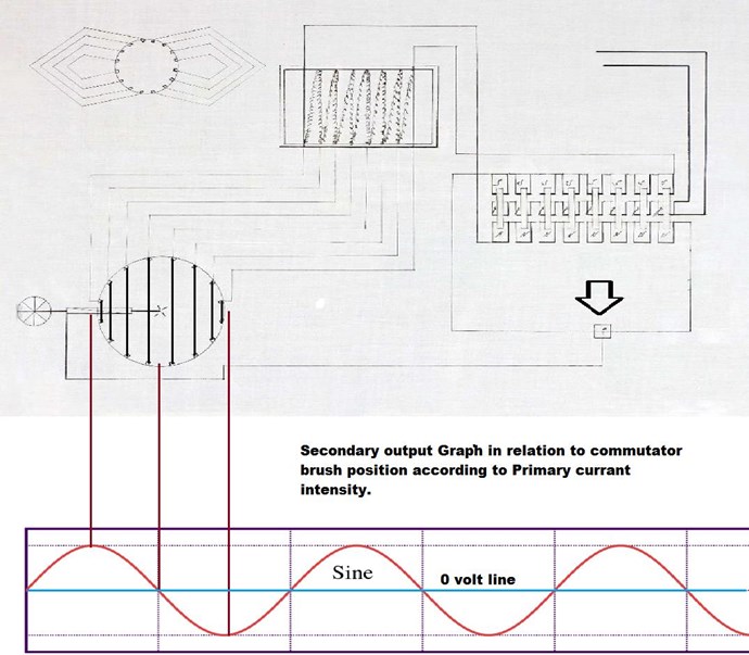
What happens in the Figuera device I think is something more than a current pumping in the armature, caused by the back and forth movement of the magnetic field lines of the armature that is confined between the two Bloch walls, but I do not know why. it may be due Added feedback, maybe?

I have thought to make my cores with sweet iron rods (electrodes without coverage) of a size of two inches in diameter, and a length of four inches. The enameled copper wire of 1 mm will be fine for the inductors?

The armature will do it with a core equal to that of the electromagnets and an inch and a half long, with 0.3mm enameled copper wire.

A set of 6 pick-up coils with 12 electromagnets, shaped like honeycomb, configured for 1000 w each coil, could be suitable.

For the G part I think that a C core or a flat disk could be adequate. Correct me if I'm wrong, please.

Ah! One question: Could two threads be used in parallel for part G, instead of one? I don't know. It's a mistake?

Regards...

(Editado)

Saludos...

Ourbobby posted this 05 May 2019

Hi creasysee,

                        yup, blink program works. where i thought i had clock pulse   this was in fact a faulty register chip intermitrntly shorting to earth. blink test works, o in theory board works. there is no clock output from pin 35 on either Jan or feb sketches.


regards

ourbobby

@ marathonman.

all the reading in the world will not teach as much as the combination of theory and practice. this is why i muck around to see what is happening. next time i read the subject will make more sense. thanks for your assistance


ourbobby


Dadrev posted this 05 May 2019

@ Marathonman

Uppss!

Thank you for your kind invitation to read the thread again. I'll do that.

Regards ...

Saludos...

  • Liked by
  • Vidura
  • Marathonman
Ourbobby posted this 05 May 2019

Hi creasysee.

occurs to me it might be a compiler issue. what program did you use to compile this code Feb11a?


regards

ourbobby

Chris posted this 06 May 2019

@All Readers, I agree with Marathonman!

Well summed up and nicely put Marathonman!

Much information is shared here and resources on my website. hyiq.org.

   Chris

Aetherholic posted this 06 May 2019

Also everyone should read the results of the experiments that have already been done and published on this thread. All the answers are there to be interpreted and used in further development, both success and failure. I have so far built 2 different working part G's and built a full array of coils and published some results. When Marathonman finishes his part G there will be 3 different versions of Part G working. Build upon what has already been done.

Aetherholic - One truth, One field

Chris posted this 06 May 2019

I also agree with Aetherholic!

This forum contains so much information! Its laid out in a fashion that is easy to follow.

This forum also has perhaps the best support personal ever situated in one place!

All ready, some not yet open to the public, Successes have already been reported. So some here are very knowledgeable, very qualified to help others!

   Chris

Dadrev posted this 06 May 2019

A pesar de lo que pueda parecer, me siento cómodo en vuestro foro, y entiendo que, a veces, se pueda pensar que la gente llega y quiere todo hecho en bandeja. No es mi caso. Llevo una semana con vosotros y me congratulo de poder dedicar todo el tiempo posible a la lectura de todos los hilos. Mi ánimo, al preguntar, no era más que por compartir de alguna manera con el foro, lo que quiero hacer. Nada más.

De hecho, el dispositivo Figuera Blasberg, no es prioritario para mí ahora, lo que no quiere decir que no sea de mi interés investigador. Saludos...

Nota: escribo en español porque quiero que se me entienda bien, y mi inglés es deficiente. Espero que no os importe.

Saludos...

  • Liked by
  • Chris
Dadrev posted this 06 May 2019

@marathonman Ud. Sin duda se refiere a Buforn. Blasberg fue su electricista ayudante, alemán, y que colaboró en el desarrollo del dispositivo. Blasberg conocía bien los efectos del electromagetismo. Saludos...

Saludos...

Chris posted this 06 May 2019

Tenga la seguridad de que está seguro aquí con nosotros Dadrev. Podríamos pedir mucho pero somos un buen grupo!

   Chris

Ourbobby posted this 07 May 2019

Hello,

           I have the arduino program running at last. all the issues can be traced back to dodgy components, most notably the 74f299. I have tried altering the istep and ishift to slow the sequence down so i can visually see the changeovers during the shift. i think this is going to introduce different coding as just changing the values for these two variable does not seem to work. anyway here is a photo of the first four in the steping sequence. 


Does anyone think that the sequence is not correct? I am not sure but should i be getting dual pulses on steps 2,3 and 4?


regards


ourbobby

  • Liked by
  • Vidura
  • Chris
Vidura posted this 08 May 2019

hey Ourbobby,

the pulses are not correct, they are double in traces 2,3,4 should be simple(edit: depending on the part g shape, for the E ir C shaped cores it could be correct, a foreward and back movement,but not for the toroidal part g)also the overlapping is missing(?), seems to be a code issue. 

vidura

Ourbobby posted this 08 May 2019

Hi Vidura, 

               Thanks for the reply. Yes, I was curious about the extra pulses coming through and i expected an overlap, all beit very small. the code is s provided by creaseysee i believe,  on another site. the problem might be the code is treating the delay as a pulse. will have a go at repairing this.


code here, (edit) actually the code there now is an earlier version I haven't tried that one yet. https://drive.google.com/open?id=1Qw7lNVZ-Yfgnw79gH9t_yHQc_0RwuPSn


regards


ourbobby

Aetherholic posted this 08 May 2019

Marathonman

Yes, absolutely correct. The electronic switching needs to mimic exactly the sinusoidal movement, brush contact area dimensions and the contact with the windings so the number of devices that are 'on' will also vary during one cycle due to brush and winding geometry to create the same contact area as the mechanical version. In my case, at mid point there are more windings in contact with the brush than at the end points which changes the separation window between the inductances during the cycle.

Aetherholic - One truth, One field

Ourbobby posted this 08 May 2019

Hi guys,

             have got anther code by creasysee Jan version. working well. I have a photo here. very slow time base on the scope 2 secs. I think the Rigol doesn't like it to slow. anyway. the mistake i thiught last post with photo was double pulses. the double pulses are actually the return pulses from the left to right then right to left. the slow time base allows us to clearly see this. one thought only one pulse showing for 0 and 7, should there be two pulses? good work to creasysee for his coding.

One small glitch you might notice i the small pulse at change over in the middle of the photo. it seems to go through the total set of

outputs


now for the hard work.

regards

ourbobby


  • Liked by
  • Chris
  • Aetherholic
Wistiti posted this 10 May 2019

Hey MM! If you wish to add a "support button " to this tread to have some financial help, just let me know and pm me your PayPal information. I will add it for you.

Keep up the good work!

Ourbobby posted this 11 May 2019

Hi guys,

            I found this article in my search for hysteresis and calculating the saturation of the cores. very neat and i am going to build one to see if it helps me. 

https://www.nutsvolts.com/magazine/article/probing_cores


regards


ourbobby

Ourbobby posted this 12 May 2019

Hi guys,

             12  coils wound 16 to go. have run out of wire will have to wait until next week until i wind the remainder. using 0.8mm wire. as per recommendation in multiple winds per spool. have ordered some ir1201S gate drivers.


regards


ourbobby

  • Liked by
  • Chris
  • Vidura
Ourbobby posted this 14 May 2019

Hi marathonman,

                            thanks for the advice.i have not wound the coils for the secondary yet. i have located an old welder that has lots of thin laminations. i'm gonna cut some of these down for the secondary cores. i used .0.8mm wire because this is what i had available.. i don't mind if it is a bit small for the moment. also, reading the advice at the beginning of the thread, the suggestion was to break the coil winding into multiple parallel winds. this is what i have done. these are small coils and the power going into them might not be as large as the big generator you are looking to build. i do understand your advice about the different sizes for the cores. there was one thing i have been thinking about. the secondary core, can this be one long core? or do they have to be individual? even could it be a toroid? if the primarys are place in a circular formation .


i suppose if we are using single winds on the cores, and havinga controls current and voltage input, then we are not going to cause any unnecessary inrush of current to the coil. the only issue i see is that the current being fixed around 1 amp the voltage will have to be variable to find out if the primarys are giving enough mgnetic flux.


regards

ourbobby

  • Liked by
  • Chris
Ourbobby posted this 14 May 2019

Hi marathonman,

                           thanks for the advice. i have cut the primary cores in half again to 1.5 inches in length. so i shall be using multiple primarys glued together. what i do not get at the moment is the magnetic strength recommended using large gauge coil winding and single layer. and especially as the input voltage is controlled. i also seem to remember you mentioning using foil as the winding. i have thought the magnetic strength was related to turns ratio, and that for example many turns of smaller gauge wire can give good magnetic strength. i get the resistance of small wire and many turns acting as an impedance to power gain. to manifest greater magnetic flux from large gauge coils would require greater increase in power input. the concept i do not get yet is how a larger magnetic flux field is created when the primarys are wound to minimise flux development. the only explanation i can think of is that the dc component required to maintain the energy level within the generator comes from the accumulation of energy from the overlapping pulses which is then able to be stored in the spare space of the primary coils field, which have not been wound to optimise there flux density. thus avoiding saturation. if so, very clever!


regards

ourbobby

  • Liked by
  • Chris
Ourbobby posted this 15 May 2019

I meant secondaries! I was tired when i wrote that. i do have copper foil 50mm wide. with the single layers i was referring to a photo that gave me the impression that multiple single layers were being wound with larger gauge wire to reduce resistance. i can see now why i get confused. too many changes while confirming correct build. i am off to bed, its been a tiring day.


ourbobby

  • Liked by
  • Chris
Ourbobby posted this 15 May 2019

Hi marathonman,

                            did you mean to include any images with your description of brushes and winding?

edit: i can get 0.05mm foil too thin?. would make wind look very neat and no bobbins!


ourbobby

  • Liked by
  • Chris
Ourbobby posted this 16 May 2019

Marathonman,

                       i had read the pages you refer to. they did not connect with me from the comments you made. as i have stated before, sometimes it is necessary to actually make something to understand what is being stated or taught. being able to recognise an event comes with experience. i am going to give figueras away for a while until some parts i have ordered arrive. then i'll connect it up and see if i have learned anything!

thanks for your assistance

edit: also, i am working on the solid state driver circuit and not the commutator model. two different emphases

ourbobby

  • Liked by
  • Chris
alset posted this 19 May 2019

Hi,

The electromagnet force is proportional to (N•I/Lengthair)^2 being Lengthair the air gap between its poles.

IMO it is not mandatory to fix a ratio of primary and secondary lengths. The longer the air gap is the weaker the electromagnet is. While it could be helpful to use a shorter secondary it is not the only configuration available. You can always modulate both fields with the ratio of maximun and minimun current in each electromagnet to sweep the whole secondary.

I think it is easier to modulate both fields strength with the current ratio Imax/Imin than using a fixed length ratio. Both are possible ways, but one seem simpler that the other in my view.

Adjusting Imax is simple: more or less voltage; but it is important to have the means to adjust also Imin. For this reason I think that it is important to have the possibility to adjust the impedance of the regulator (part G).

Regards

  • Liked by
  • Chris
alset posted this 20 May 2019

Very easy. Just double the current on the electromagnet and applying the equation I posted then its field will keep the same with twice the length. Equation for force in electromagnets are well known equations, and they take into account the decrease with the distance squared.

When I wrote Length-air I meant not the air gap between the primary and secondary, but the distance that magnetic lines travel along the air (low reluctance) to close its path going from one pole to the other. This is the meaning of that term into the equation. For this reason the longer the air path between its poles the weaker the electromagnet, being the rest of parameters equal.

Regards

  • Liked by
  • Chris
Ourbobby posted this 21 May 2019

Hi,

       have wound 14 coils for the first attempt for the primaries. i have changed the wire to 1.06mm, each coil has 330 turns and each weight pretty close to 320grams.  i have been looking at my G configuration and conclude that the hollow bar may be overkill for this first build. also, it is going to be a problem getting it machined down  to a smaller size. does the part G have to be solid iron or can i use a laminated core?

regards

ourbobby

alset posted this 21 May 2019

Quoting your post:

"i do not care who on this planet states that according to their equation it is supposed to be that way. there is no 3 inch core or magnet on this planet that can project a 6 inch field, not you or anyone else for that mater."

Amen brother.

  • Liked by
  • Marathonman
  • Chris
Ourbobby posted this 22 May 2019

Well i have read the part G all wrong. my understanding was that the magnetic flux created from the input  created a choke effect whereby the field acted as a resistance. next i read on another forum that a closed field, such as a toroid cannot produce a magnetic field because the poles need to exhibit there polarity. they cannot in a closed field. i also seem to remember seeing a core from UFO that appeared to have a 35 degree notch taken out to accommodate the magnetising field. it would appear i now have to look for another  peice of hollow iron rod! just when looking through the posts i see that here is mentioned by Peter (25 may 2018) of his core at 45x60x185 when calculated out comes pretty close to my final calculation. Frustrating!

  • Liked by
  • Chris
Ourbobby posted this 22 May 2019

I was going to ask you about the configuration of the bs2101f-e2-driver, posted earlier. we all require patience when learning. your constant outbursts are not helpful. there is a lot going on in the Figueras device, you understand it, many of us do not. if information becomes blurred, this is as much your fault as ours. I have invested time and energy, as perhaps others have, although not as much as you have. i respect that commitment. if you contribution is to end. so be it. i shall go back to something else and cut my losses. adios!

my question to you initially was regarding the Vs connection to the IgBT and the Part G. I do not quite understand this connection in relation to the input and output voltage connections. it seems that the part G is connected to common ground. i have read design sheet DT97-3 in an attempt to clarify the role of Vs in this instance, to of no avail.

thankyou

ourbobby 


  • Liked by
  • Dadrev
Dadrev posted this 22 May 2019

@ourbody En el hilo se mencionan varias configuraciones de las conexiones eléctricas con la parte G. En la patente de Figuera, a la parte G sólo llega la fase a través de la escobilla, la cual, mediante el giro sobre los hilos, reparte mayor o menor corriente hacia los electroimanes N y S. Sin embargo, en la última cofiguración de este hilo, se mencionan DOS escobillas: una fase y un neutro. No entiendo por qué lo hacen, y me abstengo de preguntar para no escuchar improperios estúpidos que no ayudan nada. Saludos...

Saludos...

Ourbobby posted this 22 May 2019

Thank you for your positive comments. it seems that you are a very capable person. it is a pity that you offer abuse to many people on different forums. earlier in the thread you quote a generous and caring approach. so why now the mr bad guy? on another forum you actually threatened to shoot someone. i know that this is not the real you. the real you is a thoughtful caring person. i must wonder if there is a deeper reason for your outbursts. Anyway, i shall keep my secrets to myself. i personally do not have your intellect and scientific knowledge. you must wonder why people leave threads when offered an opportunity not to be missed?


ourbobby

JohnStone posted this 23 May 2019

Hi all,

Finally I arrived here where Figuera cause is still alive :-) Some of you contributors might know me from other threads. I was silent now for several years but now - after my retirement - I search for new shores and want to deal with Figuera implementation.

I am a trained electronics engineer. But I know very well, that my training coverd a small part of the reality only. So please understand that I will be mostly silent for now while reading the wealth of contributions and learning basics of figuera configuration in my lab.

Thank you all for your contributions that gave me a steep learning curve up to now. 

Rgds

John

Cornboy posted this 23 May 2019

 Welcome John Stone, great to have you here old friend, your electronics experience will be very handy for a digital version of the device, i am sure you will be able to help.

 Please read right through the thread, as there is invaluable info here.


 Welcome aboard John. 


 Warmest Regards  Cornboy.  smile

JohnStone posted this 23 May 2019

Hi Cornboy :-) Thank you for your warm welcome. Great you are active here! Looking forward for collective success.

Ourbobby posted this 01 June 2019

Hello,

          my build is further delayed. i only order 10 Ir2101 drivers when reviewing driver circuit i will need 16 drivers. 2 drivers for each set of primary magnets. have ordered extra so i can build extra magnets into the build later on.

will report when build complete.

regards

ourbobby. 

  • Liked by
  • Chris
Ourbobby posted this 02 June 2019

Actually, 8 or 16 Ir2101 will work. the issue i see is the driver going through high-low and returning low-high with 8 drivers or with 18 going through high-low and returning high-low from the offset on the parallel series of magnets. i might think that the 16 would give a more pronounced ac wave as opposed to a shorter ac wave from 8 drivers. a suck it and see scenario methinks.


ourbobby

  • Liked by
  • Aetherholic
  • Chris
Vidura posted this 02 June 2019

Great , and very skilled building MM. I'm eager to see the first tests of this beauty all assembled!

Regards Vidura

Cornboy posted this 04 June 2019

 Hello All, finally got some time to play with my commutator, it is set up with Positive and negative feed back comm switch, and the feedback timing will be adjustable a full 180 degrees, just need to fit housing into a stand of some sort.

 Will be building 6 x coil triplets from modified audio crossover inductors with laminated cores for the inducers, and modified, shortened bobbins with as many offcuts from lams from the crossovers, that can fit, and then filling the air pockets with iron dust and epoxy.

 Regards  Cornboy.   smile


Cornboy posted this 04 June 2019

Very nice build skills Cornboy looks very good.

i am curious as to no windings on part G so are you connecting it to a wired core for a two piece part G?

good idea about the modified inductors, will be easier if all the wiring is at the non secondary end and i see you implemented 2 to 1 ratio, very good.

i also realize you have some really nice tools to work with, must be nice.

keep up the great work.

Regards,


Marathonman


 Hi MM, yes 2 part G + R, hopefully i will be able to try several different open and closed core magnetic resistances, to feed the primaries, including a split toroid  and c core.

 Keeping everything small to start with to keep cost down.

 Thanks  Cornboy,  smile

  • Liked by
  • Chris
  • Marathonman
Cornboy posted this 05 June 2019

 Smooth as silk MM, good job.

 Regards  Cornboy.  smile

Ourbobby posted this 05 June 2019

Hello,

         I wonder if I might ask two questions. first from which end of the parallel primaries do we count 1 to16. is is sequential like a dil ic? Or is it start again at the top on the other side? the other relates to the laminations. i am recovering some from an old welder. they are 38mm wide by 0.33mm thick. i don't think they are grain oriented, though they are not SS. i have decided to rewind all my bobbins to reduce the volume of questions i might ask using solid cores if my results are poor. generally paint seems to be used as the separating medium when compressing laminations into the forme. would this be all that is needed?

I have my digital driver set up and working courtesy creasysee, working on the power supply. i should have my ready by summer which is a long time away for me!

thank you

ourbobby


  • Liked by
  • Chris
Ourbobby posted this 05 June 2019

Hi marathonman,

                            thanks for the reply. i am uploading a image from patent. as you will see there are couple of drawings of connection. one aztecy looking drawing that indicates looping for each n or s row of coils. with the numbering its all about setting up the buffers for direction of switching. for example, i think it is possible to run this in a parallel fashion with the two north faces from adjacent coils stepping through. but as i am following your argument, it is important to get the correlation of coils in the correct sequence, eg 1 and 16. so is it the counting as shown on the connection of this image i have uploaded. that is position of first and last primary coil=1 and 16?

on the laminations, the welder has been sitting at the wreckers for some time and there is lots of fine rust formed between laminations. so i must clean this off and then repaint. issue is best good thin paint type that will also hold lams together while i play with the cores.

thank you

  • Liked by
  • Chris
Ourbobby posted this 06 June 2019

so the aztecy drawing at the top left is a simulation of what should be occuring?

  • Liked by
  • Chris
Ourbobby posted this 06 June 2019

This is what i was thinking with the two stepping procedures. if 1 is first primary and 16 is last primary then there are two sequences to my mind.

1)   1 - 9, 2 -10 , 3 - 11, .......8 - 16

2)   1 - 16, 2 - 15, 3 - 14,.... 8 - 9.

To my mind there might be a difference in the output as the "resistance" is shared differently between the two stepping procedures. ididn't express myself very well before.


ourbobby

  • Liked by
  • Chris
Dadrev posted this 08 June 2019

@MM

Gracias por este post tan explicativo y conciso. Creo que todos agradecemos su esfuerzo. 

Dadrev

Saludos...

  • Liked by
  • Chris
  • Marathonman
Ourbobby posted this 08 June 2019

Hi marathonman,

                           thanks for the explanation. it is possible to read/consume a total thread and be non the wiser. unless one was a demon with a photographic memory with instant recall. not me unfortunately. i return to areas i think are relevant on the thread. such is the lot of a student. 

this weekend i am epoxying the laminations. i have only 164 laminations  (33x0.33 x 520) that i was able to rescue from the wreckers. this will just enable 16 x 52mm long cores and 8 x 26m cores with a 27mm thickness. so if i need to extend the primaries i will have to use a different core material. this should be enough for the pilot project.

regards

ourbobby


  • Liked by
  • Chris
Chris posted this 09 June 2019

I agree whole heartedly MM!

Time is critical for so many these days, but if people want it, then Time is necessary to learn and absorb critical information!

Work is required by those that wish to learn, there are no shortcuts! Shortcuts results in failure and there is no excuse for failure with so much information available today!

   Chris

  • Liked by
  • Marathonman
Ourbobby posted this 09 June 2019

Hi marathonman,

                            my schedule at the moment is littered with objects that i have to remember. i am reminded of a russian biography of the mnemonic man, "The Mind of a Mnemonist" , who for example, would set up  say a shopping street he knew well and walk along the street placing objects into the shops. to recall the objects he would walk back up the street. too easy for some. a bit like rote learning times tables. not done these days.  for myself at the moment time sharing is a good description. once i get figueras generator going, then thedesire for detailed knowledge will kick in.

here is a photo of the first casting of my laminations. i will cut the cores to size from the cured block. one more block to epoxy. actually there is a slight variation with the laminations finished height is about 32.5mm. my wife is complaining about the smell!

ourbobby

  • Liked by
  • Chris
  • Cornboy

Topic Is Locked

We're Light Years Ahead!
Members Online:

No one online at the moment


What is a Scalar:

In physics, scalars are physical quantities that are unaffected by changes to a vector space basis. Scalars are often accompanied by units of measurement, as in "10 cm". Examples of scalar quantities are mass, distance, charge, volume, time, speed, and the magnitude of physical vectors in general.

You need to forget the Non-Sense that some spout with out knowing the actual Definition of the word Scalar! Some people talk absolute Bull Sh*t!

The pressure P in the formula P = pgh, pgh is a scalar that tells you the amount of this squashing force per unit area in a fluid.

A Scalar, having both direction and magnitude, can be anything! The Magnetic Field, a Charge moving, yet some Numb Nuts think it means Magic Science!

Message from God:

Hello my children. This is Yahweh, the one true Lord. You have found creation's secret. Now share it peacefully with the world.

Ref: Message from God written inside the Human Genome

God be in my head, and in my thinking.

God be in my eyes, and in my looking.

God be in my mouth, and in my speaking.

Oh, God be in my heart, and in my understanding.

Your Support:

More than anything else, your contributions to this forum are most important! We are trying to actively get all visitors involved, but we do only have a few main contributors, which are very much appreciated! If you would like to see more pages with more detailed experiments and answers, perhaps a contribution of another type maybe possible:

PayPal De-Platformed me!

They REFUSE to tell me why!

We now use Wise!

Donate
Use E-Mail: Chris at aboveunity.com

The content I am sharing is not only unique, but is changing the world as we know it! Please Support Us!

Thank You So Much!

Weeks High Earners:
The great Nikola Tesla:

Ere many generations pass, our machinery will be driven by a power obtainable at any point of the universe. This idea is not novel. Men have been led to it long ago by instinct or reason. It has been expressed in many ways, and in many places, in the history of old and new. We find it in the delightful myth of Antheus, who drives power from the earth; we find it among the subtle speculations of one of your splendid mathematicians, and in many hints and statements of thinkers of the present time. Throughout space there is energy. Is this energy static or kinetic? If static, our hopes are in vain; if kinetic - and this we know it is for certain - then it is a mere question of time when men will succeed in attaching their machinery to the very wheelwork of nature.

Experiments With Alternate Currents Of High Potential And High Frequency (February 1892).

Close