The last three days I've been working on solving this, checking everything in detail and also replicated the circuit and effect from "Some Coils Buck and some Coils DONT". Here is the summary of key observations.
Corrections made
Chris: There are phasing issues, there is something wrong here.
Yes, I also mentioned in my report that I suspected something wrong with the oscilloscope settings, and finally found this cause. My Owon oscilloscope resets the trigger every now and then to ALT mode which separates the triggers for both channels, hence losing their time sync. I need to check every now and then while taking readings and manually set it back to SINGLE mode. Unfortunately most of my images posted so far may have this problem. I will watch for this and ensure this will not happen again.
Testing with Jagau's SRO
Jagau: you know the adjustment of the 5K pot in my circuit is critical right?
I was adjusting it, but did not realise just how critical it is. Following your note I was able to find that very tiny edge, just as the circuit hits saturation, where one finds the lowest resonant frequency (F). Around this, I can shift F just a little bit ranging between 0.5KHz on each side to find one value at which the waveform peaks by nearly 20% more than before or after. The actual value shown on the scope is quite stable with minor variations possibly from noise. This peak for me was between 55.02KHz and 55.07KHz with duty cycle (D) between 14.3% and 14.4% with SRO on L1 (with L2 and L3 connected to diodes). Is this is the best resonant F for driving the coils?
I also placed the SRO directly on L2 (with L3 connected to diode). Sweeping through the pot, I got a wide range of F which jumped as if in little steps to lower value and narrower duty cycle pulses. Something like this:
7.4KHz at 26%, 4.8KHz at 13%, 3.9KHz at 9%, etc until 3.6KHz at 1%. Then turning the pot further the F dropped but duty cycle rose again to 1.5KHz at 3%.
Are these values special for running the coils? Are they more important than the 55KHz? Is 3.6Khz the optimum?
Changing the direction of the L2 diode still gives the Sawtooth Waveform (SW), but the wrong side showed distorted pulse and SW every 4th pulse and worked on a wider range of F, whereas the correct direction gave clean and stable pulses, but was extremely sensitive to the position of the pot and worked on a very narrow range of F.
Caveat for newbies: most often the SRO does not start on its own. Turning the pot gets it going sometimes, but you lose your position. Then I discovered that it starts easily if you kick it by removing and reconnecting the L2 diode. This needs to be done each time that power is connected. Without doing this, one could easily mistake the no-pulsation as meaning the pot needs to be adjusted, when in fact it is already in the right position. For newbies, this tip will hopefully save you the hours that I wasted until I figured this out!
The SRO pulsing continues stably even when the E-cores are separated by more than 3cm.
SRO vs MOSFET Circuit
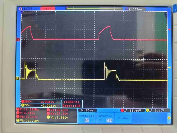
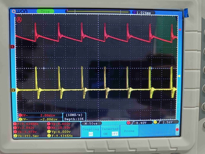
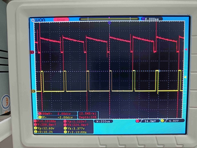
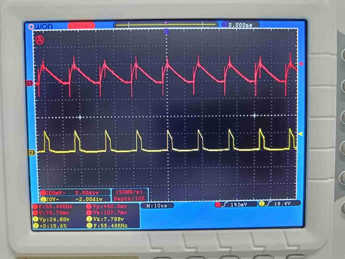
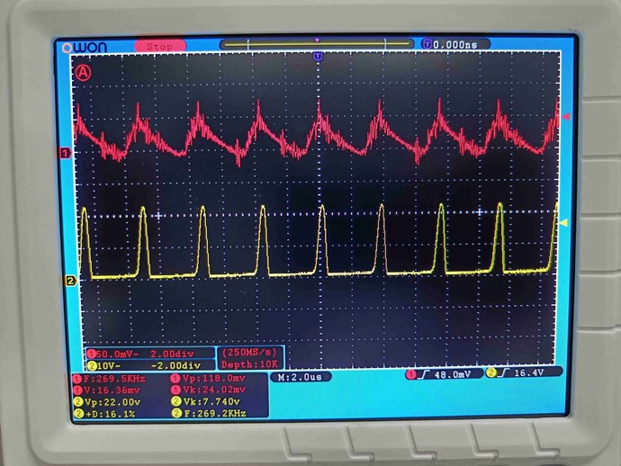
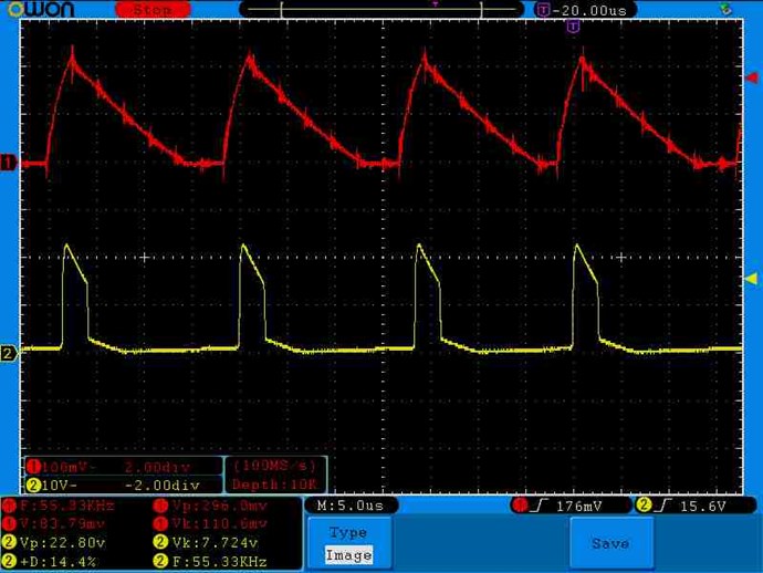
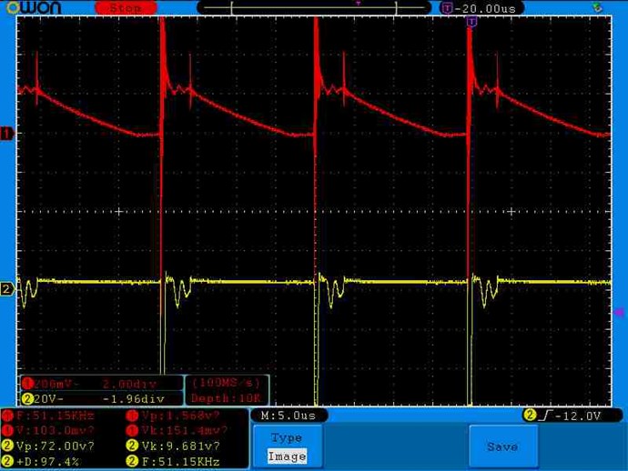
Having found what seems to be the optimum frequency with SRO for the correct SW output on L2 like this (Yellow is SRO pulse, Red is L2 current):
I then set up my regular MOSFET circuit to the same F and D values and carefully transferred the L2 connection.
The result was disappointing:
I played with W and it only raised or lowered the level. Changing F did not change the waveform until below 15KHz where it gradually began to take the good SW form, but with steep rise time and without the regauging that Chris marked as important.
Approaching 1.5KHz it got the highest, and below 1.5KHz it lost linearity.
So what changed between SRO and the regular MOSFET circuits? Only the shape of the pulse that is put out.
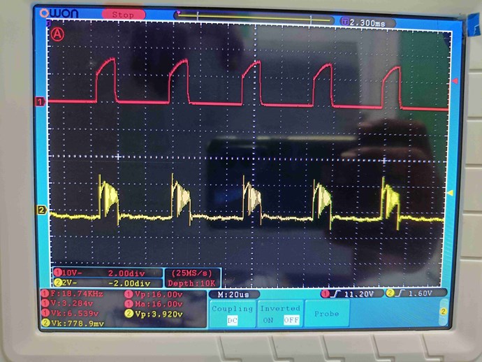
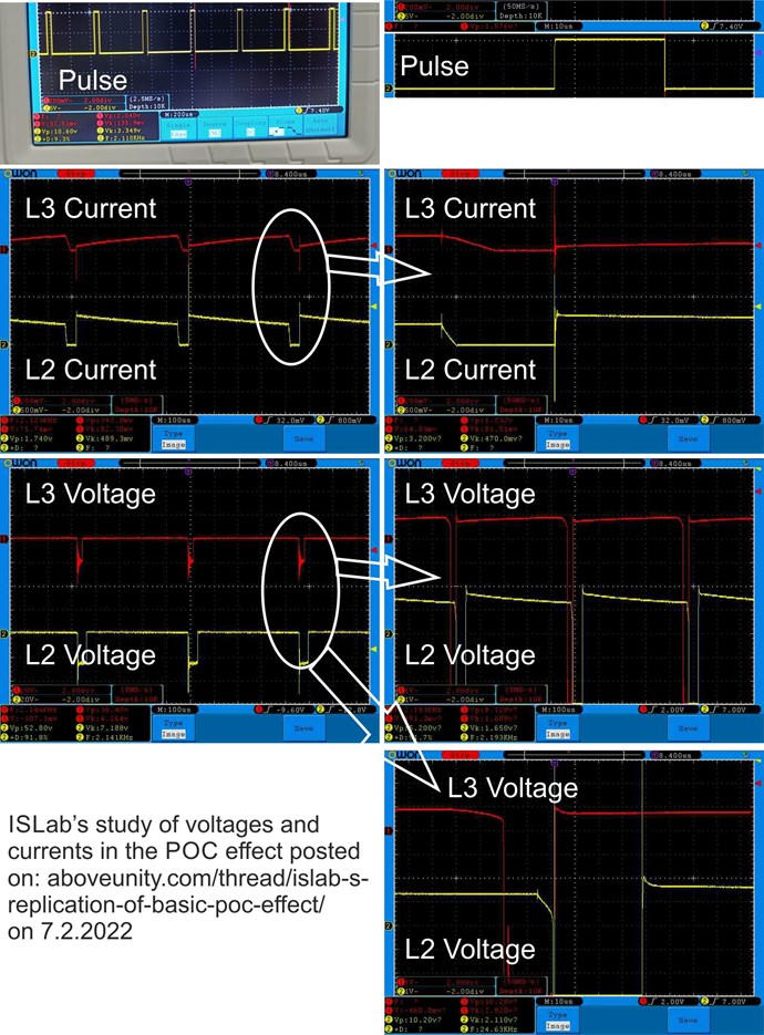
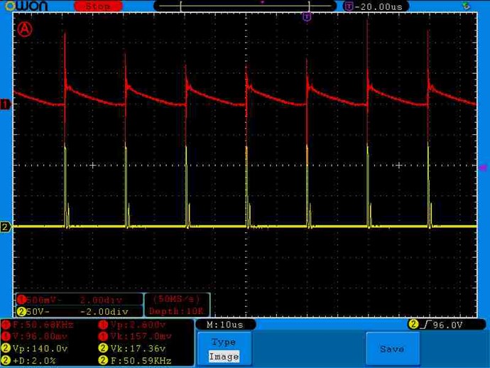
So I measured the currents of SRO pulse in L1 (Yellow) and L2 (Red):
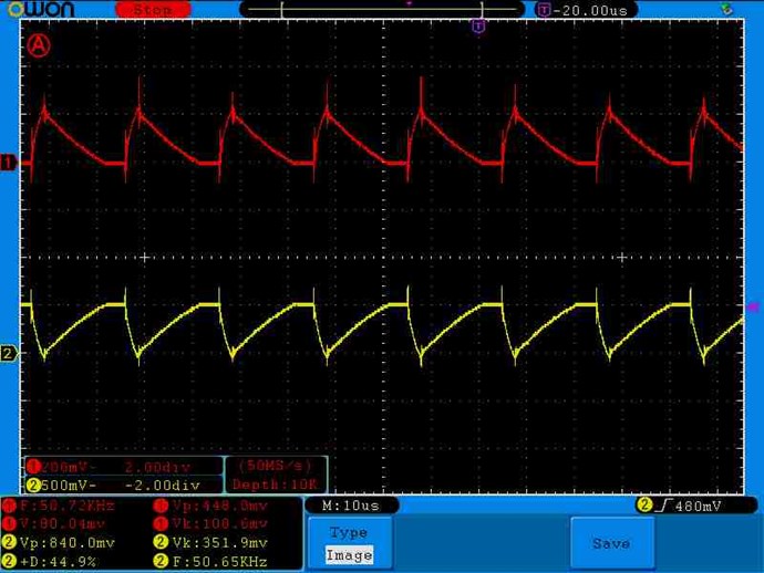
Perfect mirror image!
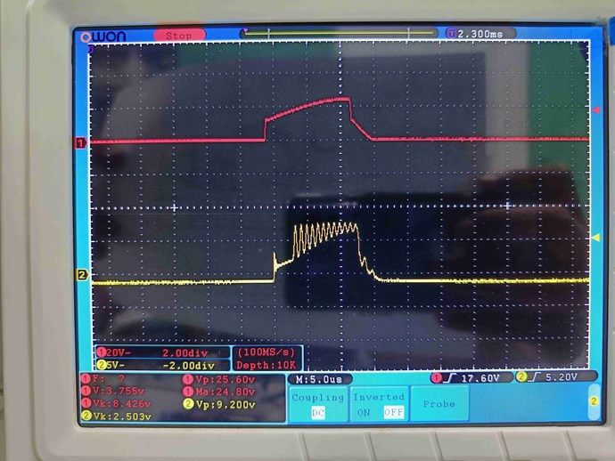
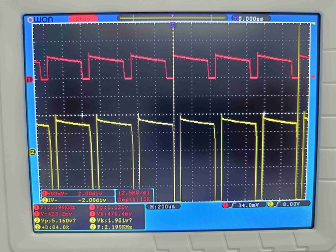
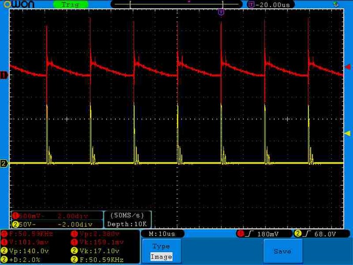
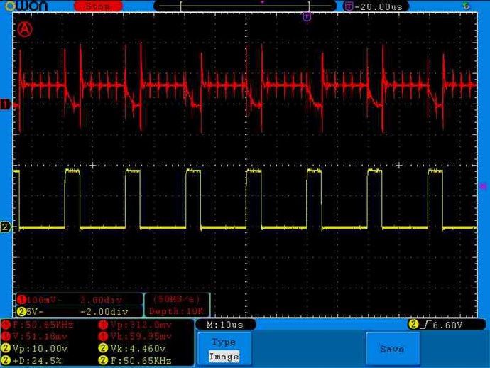
With MOSFET circuit the currents in L1 (Yellow) and L2 (Red):
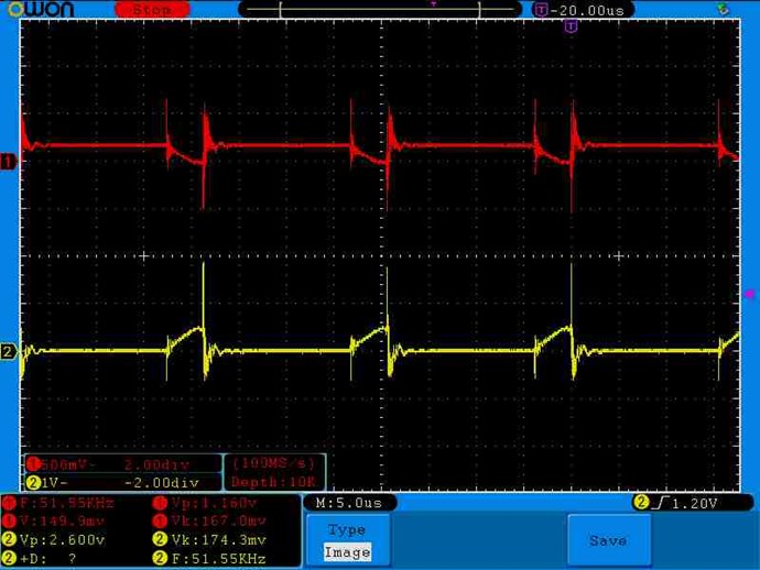
Again, perfect mirror image!
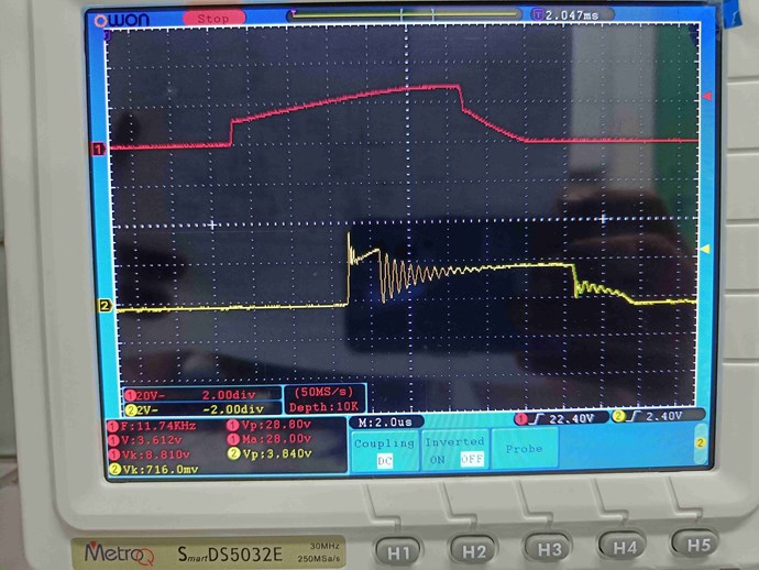
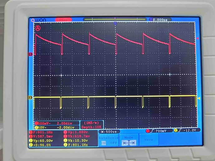
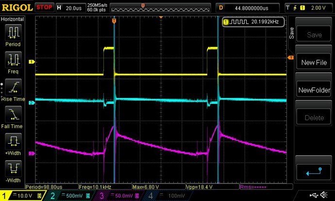
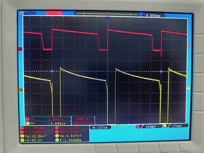
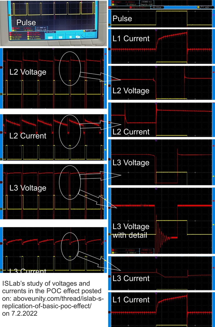
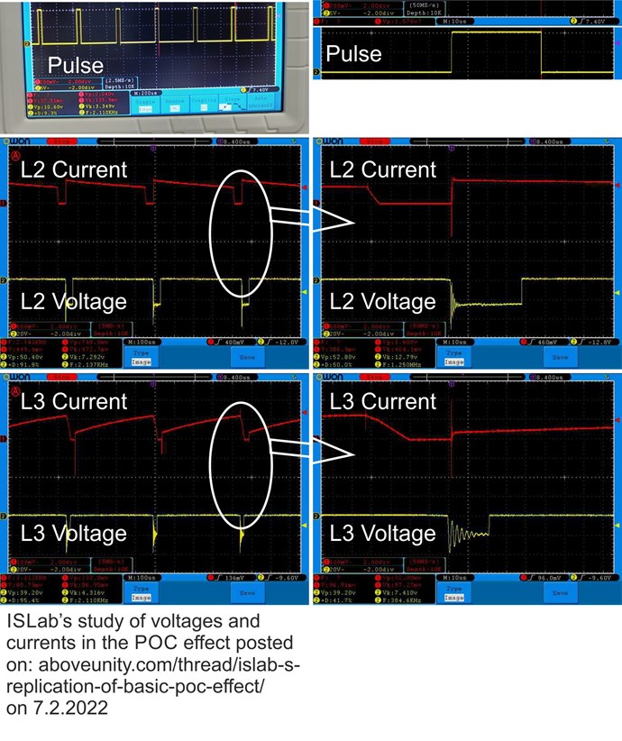
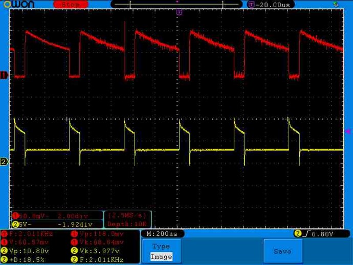
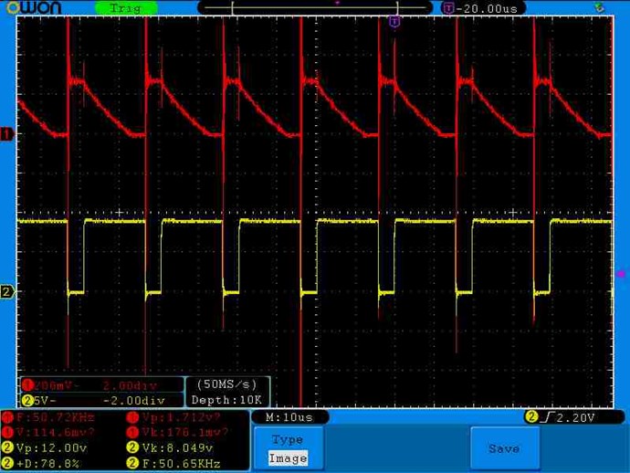
SRO voltage waveform in L1 (Yellow) measured across L1:
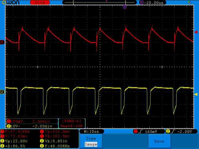
This is odd because we see a drop in voltage during the pulse (actually a negative pulse), and a positive voltage for the rest of the time when power should be generated.
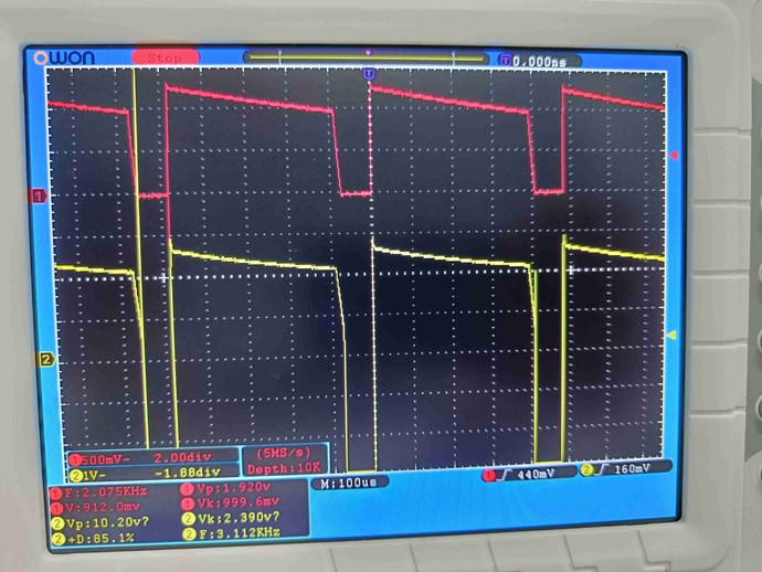
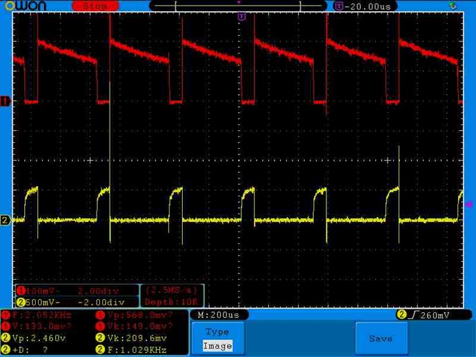
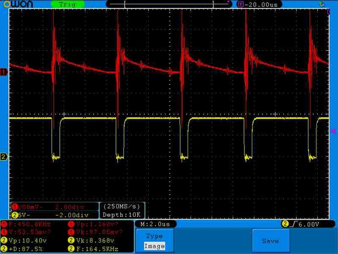
MOSFET voltage waveform in L1 (Yellow) measured across L1:
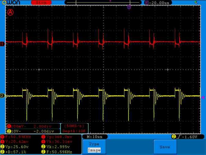
We see a voltage across L1 during the pulse and a fall to 0v after the pulse is over. This is as should be logically expected.
But this is the very opposite (inversion) of the SRO voltage.
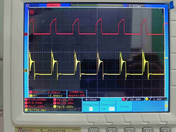
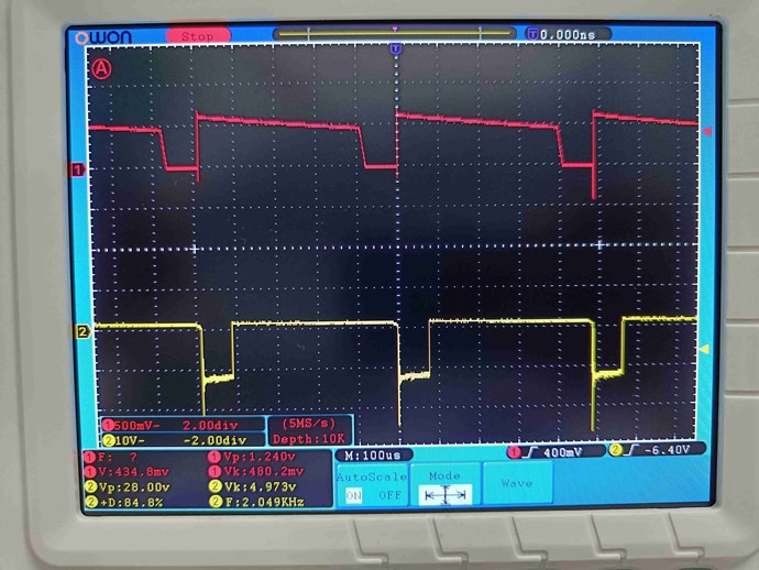
So I tried to invert the pulse to the MOSFET to make voltage across L1 to be 0v during short pulse duration and stay high for the rest of the time. Result with voltage across L1 (Yellow) and current in L2 (Red):
Regained the perfect Sawtooth Waveform!
But I'm confused as this means we are feeding power into L1 during the greater length of time and switching it off during the shorter pulse duration. Or have I misunderstood something?
I've gone through the documentation of IRF540 etc in detail. It should turn on when a positive pulse comes in, and when it turns on the MOSFET conducts and allows current to flow through L1. This should be the shorter period for asymmetrical re-gauging. But with SRO and with the inverted pulse we have L1 receiving power for the longer period of the pulse.
Can you please explain this? It seems I'm missing something very important here.
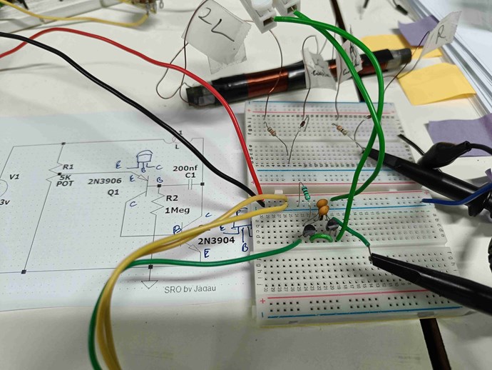
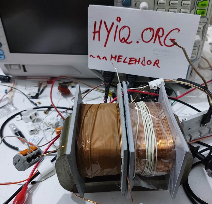
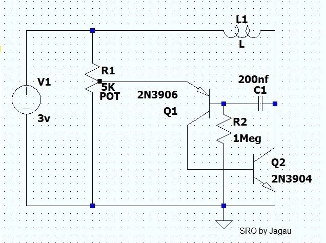
For your reference both circuits are as below.
Jagau's SRO:
Swagatam output (not shown) fed to IR2110 MOSFET driver at LIN which drives MOSFET:
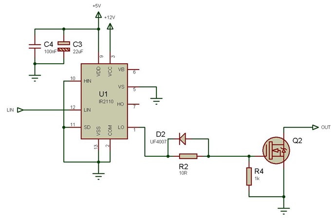
I have verified the correct pulse all the way to LOUT and MOSFET Gate, etc. There are no inversions of the pulse in the circuit. The pulse comes to the Gate as intended. MOSFET is IRF540N. Both circuits are high-side switch.
Thank you for explanation!