Partnered Output Coils

  • 13K Views
  • Last Post 05 January 2024
  • Topic Is Solved
Chris posted this 05 August 2017

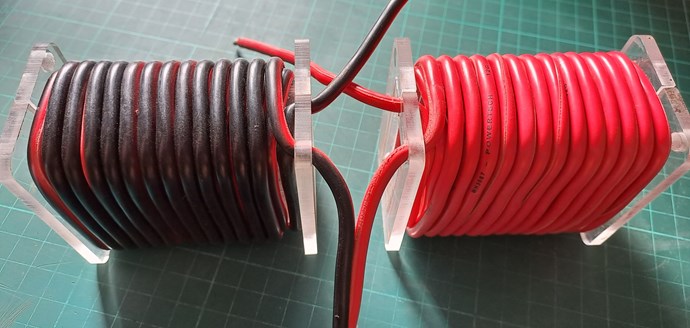
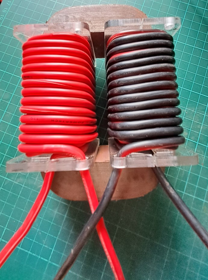
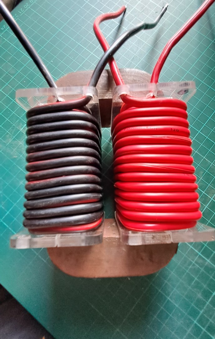
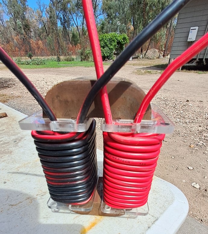
Many times I have talked about Partnered Output Coils. People call them Bucking Coils. I prefer not to use this terminology. Its a bit confusing. I use a Sudo Diagram:
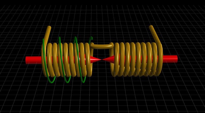
I have been through the "Common Mode Choke" and why Partnered Output Coils are different in the Timing Thread.

People in general seem to have a largely misunderstood inception of Partnered Output Coils, or Bucking Coils in general.

Andrey Melnichenko also shows a Bucking Component to his Coils. But the Coils were not Bucking as we think of Bucking.
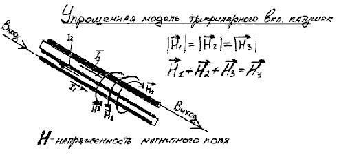
Here is an example of how it is a misunderstood area of Science. Itsu is an excellent Experimenter, this is not intended as a dig, just an observation:


Studding this video, it is obvious there has been a lot of effort gone into this. A lot of work! But Itsu is missing something, something that is the most important of all! Can you spot what it is?

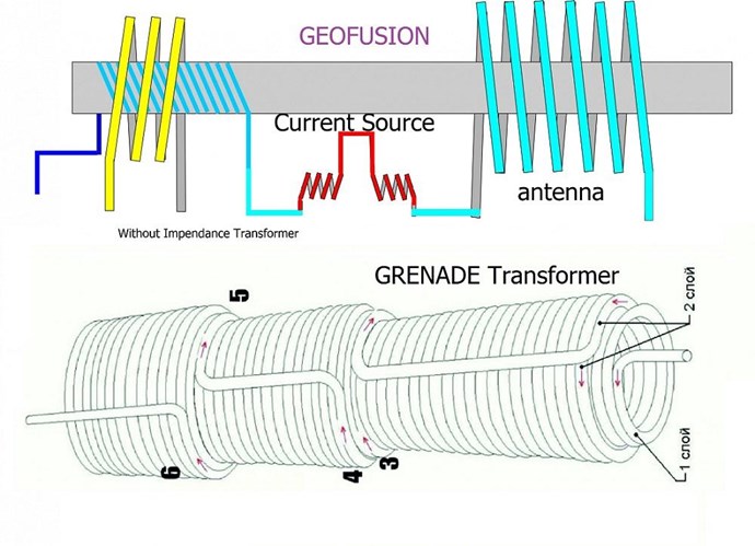
His Grenade Coil is wrong! This also pointed out in the comments.

The Grenade Coil must have, what would normally be thought of as a "Non-Inductive" Component, a Bucking Component! Actually, we will find, as time goes on, this is Highly, extremely Inductive!
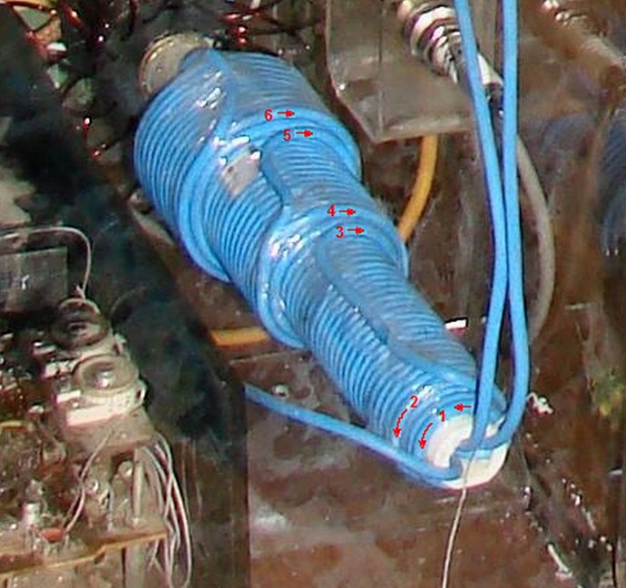
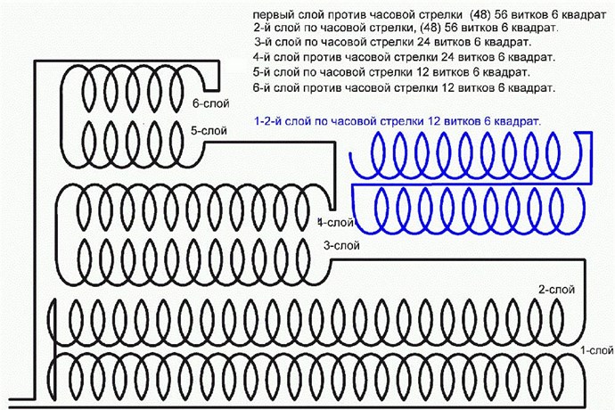
Turns 1 and 2 are Counter Clockwise, turns 3, 4, 5 and 6 are Clockwise. 
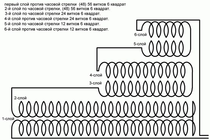
Ask yourself the question, how is it that a huge amount of Electrical Power can be extracted from a NON-Inductive Coil?

Also from Ruslan Kulabuhov
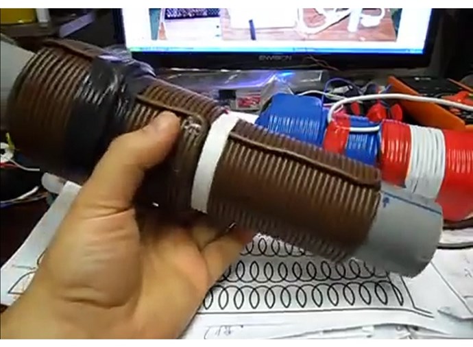
It is actually this Extremely Inductive Component that makes a Common-Mode Choke work as it does!

Floyd Sweet also shows this exact same Bucking of Magnetic Fields:
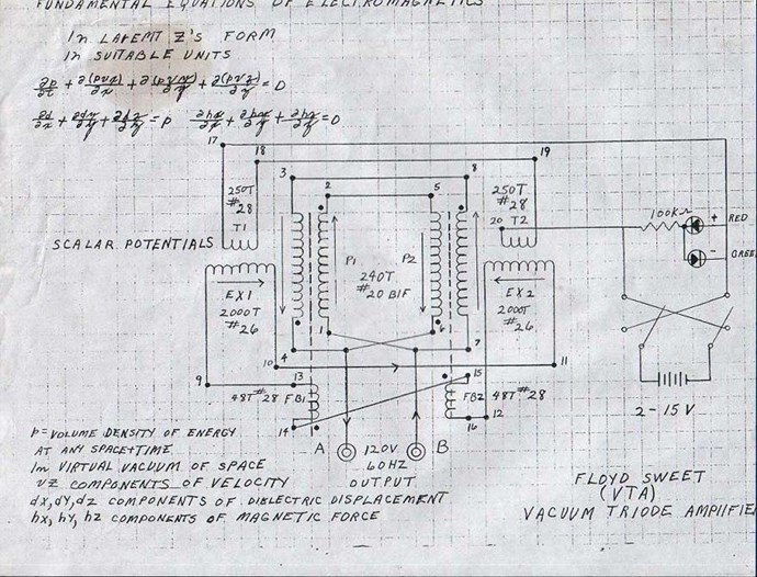
 

The VTA Description is as follows:

 Consider for a moment the construction of the triode which includes the bifilar coils located within the fields of the two magnets.


When the current in one half of the conductors in the coils (i.e., one of the bifilar elements in each coil) of the device is moving up, both the current and the magnetic field follow the right-hand rule.


The resultant motional E-field would be vertical to both and inwardly directed.


At the same time the current in the other half of the conductors in the coils is moving down and both the current and magnetic field follow the right-hand rule.


The resulting motional E-field is again vertical to both and inwardly directed.

Thus, the resultant field intensity is double the intensity attributable to either one of the set of coil conductors taken singularly.

Now, a Right Hand Rule both facing Inwards, it is the same as:
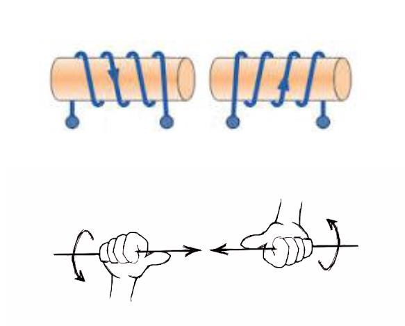
Why? Why must we have Opposing Magnetic Fields?

If the directions of the two signals are such that opposite H-fields cancel and E-fields add, an apparently steady E-field will be created. The energy density of the fields remain as calculated above, but the value of the E-field will double from E/2 to E.

By Opposing the Magnetic Fields in a Dynamic System, the Electrical Field doubles! The Mr Preva Experiment proved this to be true!

Floyd Sweet also said:

Current is deemed as a quantity or number of charged particles moving from P1 to P2 in time t, or as the charge transferred in one second by a current of one ampere. The coulomb is the charge on 6.24 x 10¹⁸ electrons. Electric fields are due to the presence of charges. Magnetic field effects are due to the motion of charges. Current is the net rate of flow of positive charges. This is a scalar quantity.


In the specific case of positive charges moving to the right and negative charges to the left, the effect of both actions is positive charge moving to the right. Current to the right is: I = da+/dt + da-/dt. Negative electrons flowing to the left contribute to the current flowing to the right.

The Mr Preva Experiment also proved this to be true!

We see a Standing Wave of Magnetic Fields! 

 This thread is for those with questions, thank you Vasile for the following question.

   Chris

Order By: Standard | Newest | Votes
Chris posted this 03 March 2023
Hello earthbound,

Best way to learn, is to get into it, on the bench and explore the most simple technology ever discovered! 1832, and now, some 191 years later and science still has not acknowledged Asymmetrical Electromagnetic Induction.🤡

WOW, if I had the opportunity way back, when I started, and now with all the Independent replications, showing the proof, its a no brainer! 

Too much procrastination is the enemy of the People!

Best Wishes,

   Chris

Chris posted this 04 March 2023
My Friends,

Never before, ever, has this happened:

 Start Here → Builders Guide to Aboveunity Machines

There are two mistakes along the way to MasteryNot Starting and and not going all the way!

Cite: Master Shi Heng Yi

On rare occasions, Sweet saw this effect, called self-oscillation, occur in electric transformers

Ref: http://merlib.org/node/5282

The Answers you seek are right here:


I have provided 11 videos on this showing you how to approach this Technology! I have given you all of the data to make this work, and more, to make this, not just a TOY, to make this Power very much more than just a few Globes!

My Friends, when I see 10 successful replications, I will release another Video showing a bit more work, again we have had quite a few successful replications already! Do the Math in these videos! COP > 1.6 in both Machines!

Tinman was the first:


Others followed, like Captainloz:


Others also, some may not want their names used? Security for people is important to me, but eventually, we must do this as a Team and make a Stand!


Some have taken advantage of this, some plunder it.

Its so simple, and so cheap! The problem is, too many stupid, stupid people in the community!


Don't tell anyone, but

We are LIGHT YEARS Ahead of the other Forums!


Best Wishes,

   Chris
donovan posted this 04 March 2023

Hi,

There is so much information here.  I read more and more every day. 

Thanks for everything, Chris.

Donovan

Chris posted this 08 March 2023

Hello Donovan and Friends,

Yes, there is a lot of data here on this forum, and some have used this data to make excellent progress!

I have collected all the data and posts from many forums over the years and I estimate about 3% of the Community are Serious Dedicated Researchers!

That's a very poor number!

Many run multiple names!

The fact of the matter is, majority of the community has been controlled disinformation for decades and I don't think any one would disagree with that! Groups of people paid to make a mockery of the Energy Field for a very long time, and yes I have a list of names when the time comes.

ChatGPT:


There are a lot of very brain dead people out there, doing the dumbest things, sadly! ChatGPT is very much smarter than these idiots! Even if ChatGPT is not completely correct!


Best Wishes,

   Chris

Chris posted this 05 September 2023

My Friends,

This post is partly for Madscientist, for his thread here: Madscientist's Non-Inductive Coil Replication

POC must oppose because of Lenz's Law.

To visualise this, we have a Magnetisation Phase:


And a De-Magnetisation Phase:


To observe the Effect of Lenz's Law, we see Drag:


To be able to achieve an Asymmetrical Machine, one must have a Symmetrical component first. 


Symmetry

Symmetry is seen directly in Newtons Third Law:

  1. An object at rest remains at rest, and an object in motion remains in motion at constant speed and in a straight line unless acted on by an unbalanced force.
  2. The acceleration of an object depends on the mass of the object and the amount of force applied.
  3. Whenever one object exerts a force on another object, the second object exerts an equal and opposite on the first.


The way I state the Third Law is like so:

For every Action, there is an Equal and Opposite Reaction.


NOTE: Newtons Third Law is Incomplete! Currently we only have: Action and a Reaction. Only accommodating Symmetrical Systems. It does not hold in Asymmetrical Systems!

Because we are dealing with Electromagnetic Induction, we have to consider this in the following way:

Output equals Input minus Losses.


Here you can see, all Symmetrical System's, can never be an Above Unity System, always a Below Unity System!

We can say, mathematically, OutputPower = InputPower - Losses. In a Transformer, where it is say 90% efficient, then we can calculate: 100Watts - 10Watts = 90Watts. So Symmetry ensures we always have a Below Unity System!


Asymmetry

An Asymmetrical System must always have a Symmetrical component, contained in the system.

The way Newton's Third Law should be stated:

For every Action, there is an Equal and Opposite Reaction, and for every Reaction, there is an Equal and opposite Counter-Reaction!


Therefore we will see: Action, Reaction and also a Counter-Reaction. Now Newtons Third Law accommodates Asymmetrical Systems!

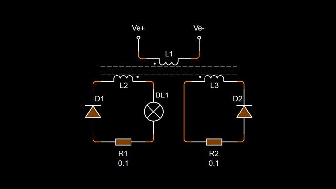
Partnered Output Coils are Symmetrical by themselves, but our System, does not consist only of Partnered Output Coils, we have an Asymmetry, because we have introduced a Third Coil to our Partnered Output Coils, our Input Coil:


We have Three Magnetic Fields:

  1. Input Coil
  2. POCOne
  3. POCTwo


Everyone should already know, every Coil that carries a Current, must always have an associated Magnetic Field, always, there is never any Exception. A Flow of Current constitutes a Magnetic Field.

Now we can say, mathematically, OutputPower != InputPower - Losses. Where ( != ) means Does NOT Equal.

Output Power can be thought of in another way, OutputPower is defined by System Design Specification.

Floyd Sweet was quoted in saying:

Sweet was also a transformer designer and expert, and he remarked that he had also observed specialized self-oscillation in certain transformers.

Ref: Energy From The Vacuum by Tom Bearden


On rare occasions, Sweet saw this effect, called self-oscillation, occur in electric transformers

Ref: Jeane Manning http://merlib.org/node/5282


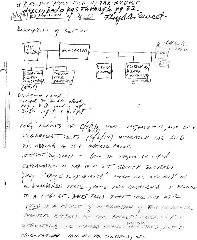
Floyd Sweet also labeled the SQM as an Oscillator, in his original Lab Notes:


Electromagnetic Induction is currently Incomplete in todays Scientific Textbooks, I have completed Electromagnetic Induction, and given Experimental Proof to support the Completion. You have the proof right in front of your eyes, its up to you to use this knowledge and apply it for useful purpose!

Of course, to Club Dumb Dumb, over on the other forums, none of this will make any sense, because they just have no idea whatsoever!

Best Wishes,

   Chris

Chris posted this 15 October 2023

My Friends,

In regards to my last post, in this thread, I want to explain something very important, something I have explained before, but no one has touched upon, except one person, which I will not use his name for the moment.

I have pointed out, before, in the Thread: The Reduced Impedance Effect, that we can have a situation, where all of the Coils Impedance can be removed, from a machine, simply by clever design techniques!

What does this mean?

Very Simple, this means an Electric "Generator" can be designed that has no Drag on the Shaft! This concept extends well beyond just the Electric "Generator"! This Concept can be applied to all EM Machines, all of them! 

The Conventional Transformer is another machine that can have this Concept applied to!

Like I pointed out in the last post, the concept of Drag is removed from the Asymmetrical Machines I have shown you:


NOTE: No Drag as we know it, means that the Potential we can achieve can be achieved very much faster than we would normally expect, because we are essentially not fighting against a Magnetic Field. We are using Magnetic Fields to Cancel, or Control Magnetic Fields.

Some would say we have Negated Lenz's Law, technically, this is not an accurate way to view the situation, but its how many have thought of this. We are using Magnetic Fields to do more work for us in a single machine, than is conventionally thought possible, because we are using Asymmetrical Electromagnetic Induction, a concept that Science has not been able to explore at all, because Science Establishment is too ignorant and arrogant to accept that they entirely missed it!

Here is some advice I posted via PM, to a member here, I normally don't get any time for PM's so I ask all to post in your own threads, and I will help:

some advice:

  • Treat your Input Coil and POCOne as a simple Conventional Transformer.
    • In a simple Conventional DC Transformer, the polarity of each Coil is determined by Electromagnetic Induction and Lenz's Law. The Phase is always 180 Degrees, represented by the Negative sign. So if you were to take two parallel wires, the Polarity would be opposite.
  • POCOne and POCTwo oppose and you can use The Right Hand Grip Rule to ensure each Diode is orientated correctly.
    • The Diode Polarity in the Circuit with POCTwo, will Increase your Input Coil's Current in one Polarity, and reduce your Input Coil's Current the other Polarity. We are aiming for Input Coil Assistance! To Lower your Input Coils Current is the Goal!
  • Ensure each Circuit on POCOne and POCTwo are isolated and kept separate until a greater understanding is obtained.
    • Have one Circuit for each Coil, manage each Circuit as required, to make steps on improvement as required.


Each Coil is always abiding by the Right Hand Grip Rule because Lenz's Law holds. If you look at each Coils Polarity, you get: Positive + Negative + Positive, and here you can see, we have a System that has an extra Input, an extra assistive force, which is an open System, allowing for Gains Above Unity!

Maximize your Machines Bucking, make the Machine Pump Electrons from the Atom, stripping away all the Electrons from the Atom if required, and Accelerate them down the Wire as a Current, where One Ampere = 6.241509074×10¹⁸ Elementary Charges per Second.


Each Partnered Output Coil is like a Battery! Each Coil must always Buck Each Other, and all you have to do is get the polarity of the "Generated" Voltage Correct!


This is so simple and its so cheap, and there are so many stupid ignorant idiots in denial, its so funny to watch these Idiots Squirm and Lie, each sentence they post, they keep making Idiots of themselves!


Very Simple, the Magnitude of the Magnetic Field of each Partnered Output Coil must be approximately Equal, and Opposite, then, when you achieve this, amazing things happen, things that the very same Idiots I mention above, have told you for many decades, cant be done, sadly! These people will become Enemies of the people very soon! They will become the Hunted very soon! Good People will start holding them accountable very soon!

The other forums don't cover any of the basics, so how can they have any direction? When they are unaware of the basic, simple principles, we hold dare and require to gain an understanding! Duuuurrrr!!!

Best Wishes,

   Chris

Chris posted this 07 November 2023

My Friends,

While Gutter Trash are still messing around with total non-sense, we are showing machines that are changing the world!

Here you will see how extremely Simple, and very Cheap these machines can be! Don Smith was 100% correct, problem is, dumb idiots do not understand 10% of what Don shared with you all, but claim to be All Knowing! Truly, they know Nothing!!!

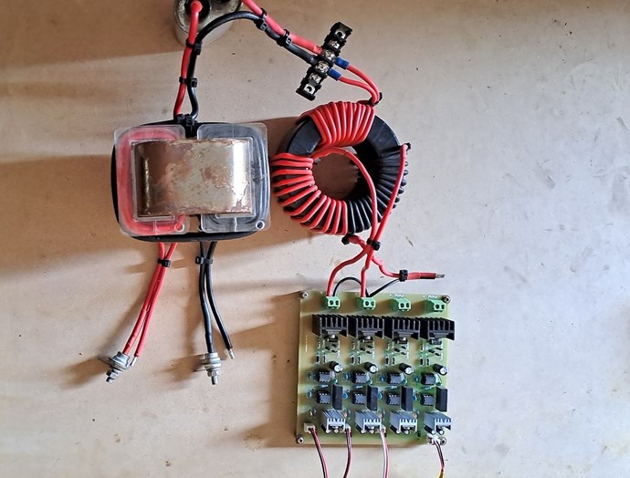
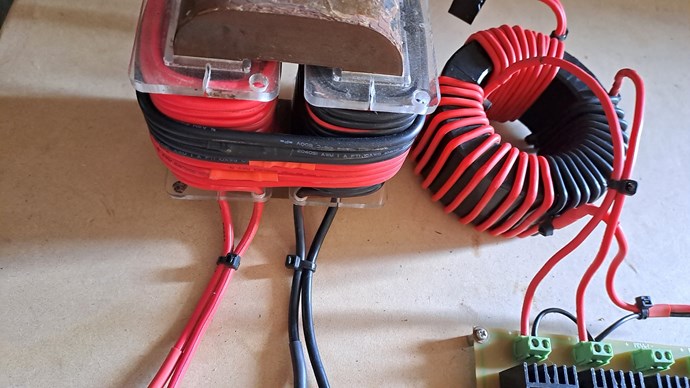
This build was a rather successful machine:


Here, you can see, very clearly, the parallel:


Some more:


I already posted the above here. Below is new to the Forum:


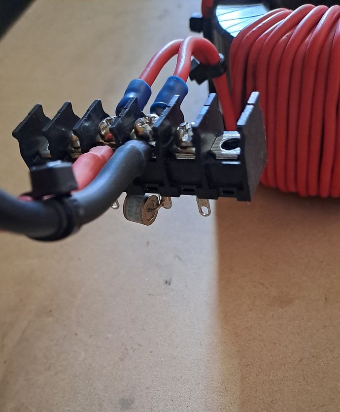
Why would I show you a picture of the Gas Discharge Tube?

Its true, McDumski Club, you know the dumb dumb club, the Homer Simpson Scientists, they have no idea whatsoever, none of this will make sense to them, but wait for it, in 3 weeks, they will be claiming it as their own, because they are Professional Plagiarists! Liar's Cheats and Bought and Paid for Shills!

My Friends, never forget this statement:


This statement is 100% correct and there is nothing here to be confused about! I have already explained it all!

Leave the idiots at the Gate!

Best Wishes,

   Chris

FringeIdeas posted this 08 November 2023

If I may take a noob crack at this.. The toroid first made me think of Ruslan... But..

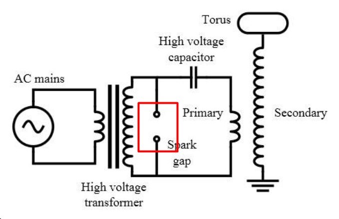
The gas discharge tube would be your spark gap.

I could be off. I'm not sure how much spark gap action those things can take before they die.

Your switching appears to be flip flopping direction of the magnetic field in the toroid, driving the third coil with AC, which is output to the screw terminals there. But that GDT is rated for 470V? The toroid appears to be more of a 1:1, not a step up. And I'm going to just guess you are not switching 230V on each mosfet.

Looking good btw. I was curious, from the other thread, how this project was coming along.

Br,

Marcel

Chris posted this 08 November 2023

Hey Marcel,

Yes, spot on on all points, you're correct.

I had to add turns in a few places, so the turns are not 1 : 1, in some places 12 to 17 and so on.

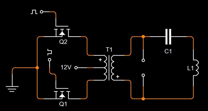
I posted the Circuit for this setup, Here:


At resonance, one can achieve quite High Voltages in the Resonant Tank, for very little Input Voltage. As you know, we have the ability to turn up our Input Voltage on our Bench Power Supply's.

It really is just a case of fiddling until we get something working, something running, and then work to optimize it. I could spend another few days optimizing this setup! At the moment, because I have a different setup running, this is just an experiment to learn more and more to gain the ultimate knowledge to know what's best and simplest!

One thing is certain, we have a small group of idiots that CANT think, or experiment their way out of a Paper Bag, fighter, you know the Banned and Disgraced idiot, he is still lost in his lunch bag from second grade!

Every experiment we do, gives us more and more knowledge to make better and better machines, those that have done Zero Experiments, they will have no idea where to go, what to do when the Lights Go Out!

There is one question I am waiting for, wonder if it comes, and who will ask it...

Best Wishes,

   Chris

Chris posted this 09 November 2023

@Marcel,

I wanted to give a little more explanation of the inferred "Spark Gap". When you said:

But that GDT is rated for 470V? The toroid appears to be more of a 1:1, not a step up.


No, we are stepping up the Voltage, its a Step Up Toroid Push Pull Transformer.

Please understand, this is the same idea, same concept as any other Spark Gap, see Impulse Pressure Wave for some back ground, so any rated value can be changed by the application of a force to close the Electrode Gap, ever so slightly. So 470 does not mean, necessarily 470 Volt Break Over Voltage, this can change by closing the gap slightly.

Also in any Tank, the Internal Resonant Voltage will always be a lot higher than the external applied voltage. As already stated.

I guess what I am trying to say, is don't get hung up on specifics that really are, or can be, Dynamic! Look at the bigger picture and the idea behind the concept. As an example, the Atom and all of its Charge and Neutral particles, will see a very important Effect, the Impulse Pressure Wave:


@00:17 seconds, "Watch out the for the shock, its coming!" and then Bang, the Shock Wave blasts everyone, what effect do you think this would have on the Atom, the Electrons in their Orbitals, the Protons, and even the Neutrons. What do you think these subatomic particles will do?

Do you think a huge number of Electrons will be thrown out, becoming Free Electrons, and the Insulated Copper Wire, will thus have many billions and billions of Electrons everywhere, free and ready to be accelerated down the wire?

Bucking Magnetic Fields are the Pump, but the Insulated Copper Wire, the Atom, specifically the Electrons, the Elementary Charge, is the particle we need to grab and throw down the Wire, with a Velocity, remembering,  6.241509 × 10¹⁸ e, or charges per second is One Ampere. So these e's must come from somewhere, we are not getting e magically, and the Atom is the only place we have e, its the only source! We are essentially Engineering the Sub Structure of Space, our Aether is being Engineered by Magnetic Fields!

No one in Conventional Science, will allude to any of this, they will tell you the Shaft is the Source of Electric Current. Hmm, really smart isn't it! Like fighter, still stuck in his second grade lunch bag! Idiots beget idiots!

Best Wishes,

   Chris

Adam posted this 18 November 2023

Hello Chris,


I’m working on a variation of this same winding on the core.

I have a few questions.


1.  What is delaying the conduction on the first pulse say with a north up? Diodes resistance or switch or maybe delay is not needed?


2. When the second pulse hits in the reverse polarity and the diodes can not allow conduction does the conduction take place in the collapse phase? Trying to prevent the collapsing field and at the same time bucking each other?


Thanks.

Adam.

  • Liked by
  • Chris
  • Augenblick
Chris posted this 18 November 2023

Hey Adam,

I believe you have answered your own question, maybe...

1.  What is delaying the conduction on the first pulse say with a north up? Diodes resistance or switch or maybe delay is not needed?


All delayed Conduction is, is Conduction that does not take place at the exact same instant as the Input Pulse, so the Conduction is delayed, due to the fact that the Input Coil is not causing the Induction, to "Generate" the Voltage, to make the Diode Conduct. The Induction, to "Generate" the Voltage, to make the Diode Conduct, comes from the Secondary Coil, that has its own Changing Magnetic Field in Time t. Which you have also answered here:


2. When the second pulse hits in the reverse polarity and the diodes can not allow conduction does the conduction take place in the collapse phase? Trying to prevent the collapsing field and at the same time bucking each other?


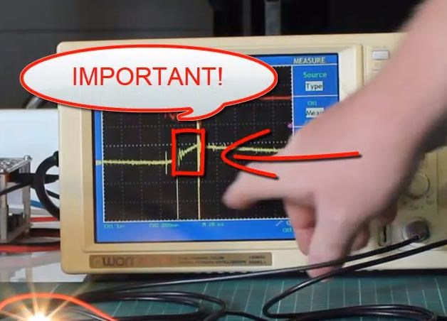
On the Input Phase, you can see all this happen in the period marked Important:


Both Partnered Output Coils have an Impedance, close to Zero, see Reduced Impedance Effect, this will make this phase much clearer, the Coils can build to Max Voltage very quickly because the Coils have no Impedance. Nothing is slowing down the Building of Magnetic Fields, due to the Asymmetry we have implemented in our machines.

If you like, each Partnered Output Coil pushes each other up the Hill, to the House of Maximum Potential, for a given Design!

Best Wishes,

   Chris

  • Liked by
  • Augenblick
  • FringeIdeas
Adam posted this 18 November 2023

Hello,

Well on your normal device you show the primary turns on and you have to delay the conduction in POC1 so it does not buck the primary until just as you turn off the primary you then close the switch on POC1 to conduct. At this point POC1 will buck POC2 wile primary is off. Then we wait till the saw tooth is at zero and hit it again.


But this device is slightly different in the fact that the primary is wrapped over both POC1 and POC2. So, what I’m asking is do we still need the same delay switch or MOV to keep POC1&2 from bucking the primary as the primary ramps up the field?


Thanks

Adam.

  • Liked by
  • Chris
  • Augenblick
Chris posted this 18 November 2023

Hey Adam,

Ah I see what you mean.

No, all Coils reach Maximum Voltage Potential during the On Time of the Input Coil.

Input Coil Conducts via the Mosfet, the Input Coils Magnetic Field Builds, and a Voltage is "Generated" in POCOne, then POCOne Conducts through the Diode, then the building Magnetic Field in POCOne creates a Voltage on POCTwo and then the Diode on POCTTwo Conducts. Always, it is the "Change" in Magnetic Field that "Generates" a Voltage, a Steady Magnetic Field is useful for Pumping Current, but has nothing to do with "Generating" a Voltage! I have shown all of this in my Video Series, in great detail.

Important: Every single Coil that carries a current, must, MUST, always have an associated Magnetic Field!

You must arrange your Coils like so: POCOne opposes your Input Coil, POCTwo opposes POCOne, therefore POCTwo must Assist your Input Coil.

The degree of Input Assistance you achieve, is where you achieve Above Unity Effects, because if you get 50% Assistance, you get a 50% reduction in Input Current Draw for the same Output.

You need to think Cause and Effect, and then apply the Asymmetry to gain Excess Output.

Best Wishes,

   Chris

Edit and please NOTE: In the Conventional Transformer, we see a Total 1 : 1 Transformation: Output = Input - Losses, so what you put In, you get out, minus the Losses in the Machine, in our machines, we don't have a Closes System, we have an Open System, the Strap or Parasitic Inductances that everyone tries so hard to get rid of, we use, we take advantage of "Generated" Voltages, and Current Distribution in the System is such that we support the "Pumping" of Charge.

  • Liked by
  • Augenblick
  • FringeIdeas
worldcup posted this 21 November 2023

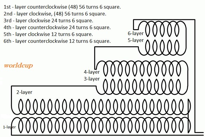
Translation :


If anyone winds, then record an video and link over youtube.


@chris, regarding layer 1 and 2, here is corrected one.. i think you wrote it wrong in your first post.


1st layer counterclockwise (48) 56 turns 6 square.
2nd layer clockwise, (48) 56 turns 6 square.
3rd layer clockwise 24 turns 6 square.
4th layer counterclockwise 24 turns 6 square.
5th layer clockwise 12 turns 6 square.
6th layer counterclockwise 12 turns 6 square.


6-layer
5-layer

4-layer
3-layer

2-layer
1-layer


Regards

Some more indeed...


Grenade first layer and second layer are the same, is wound CCW,
the rest 4 layers are all CW wound.
see Diagram below, Turns 1 and 2 are Counter Clockwise, turns 3, 4, 5 and 6 are Clockwise.      --  

  • Liked by
  • Chris
  • Augenblick
Chris posted this 09 December 2023

My Friends,

Partnered Output Coils can Power your Future, its up to you!


Partnered Output Coils already are Powering my Future and many others around the globe! Electromagnetic Induction really does work! This arrangement is an Electromagnetic Charge Pump! Plain and Simple!

Floyd Sweet used Partnered Output Coils, The Meg Team used them, Don Smith used them, and many many more! They work! They are Simple and they are cheap to implement!

With just a little work, you can do it!

Best Wishes,

   Chris

  • Liked by
  • FringeIdeas
  • Augenblick
FringeIdeas posted this 12 December 2023

Chris, from a few posts back, November 7th.

There is one question I am waiting for, wonder if it comes, and who will ask it...

Did this make discussion? Just curious.

And a question of my own, referring to these new pictures on November 7th. Maybe a bit beyond what I want to mess with right now. I have a few more basic experiments I need to run through first. But the few turns on the POC coils and the talk on resonance got me thinking.

So you use resonance in the push-pull circuit, understood. But we still need to observe resonance, or a sub-harmonic thereof in the POC coils, for several reasons, correct? So is it safe to assume you matched this with the resonance of the push-pull circuit?

And somewhere on this forum I read, sorry I can't recall where, that the lower the sub-harmonic that is chosen the higher the input voltage needs to be. Is this the reason, or partially the reason,  you are using an abrupt discharge? And what is the operating frequency, roughly?

Looking forward to seeing more development, thanks!

Marcel

  • Liked by
  • Chris
Chris posted this 12 December 2023

Morning Marcel,

Did this make discussion? Just curious.


No, we did not get any discussion on this:

There is one question I am waiting for, wonder if it comes, and who will ask it...

Ref: My post here.


I don't blame people, we are at a point where we have more visitors than ever before, but most visitors are readers and not participating actively. I think many are scared to get involved? I also believe we have a number of active readers that already have working machines, that are following to answer some of the more technical questions that arise. While I am still learning, and still have some deep questions, I have come a long way.

And a question of my own, referring to these new pictures on November 7th. Maybe a bit beyond what I want to mess with right now. I have a few more basic experiments I need to run through first. But the few turns on the POC coils and the talk on resonance got me thinking.


I am a firm believer, any and all experiments are valuable! Of course, "Generating" a Voltage on each Partnered Output Coil in the desired polarity is the key, and this experiment shows a lot more detail in the operation. Its just the Change in Magnetic Field. Magnetic Resonance between Partnered Output Coils can be thought of as the Generation of Voltages due to each Coils Changing Magnetic Fields, thus a Faradays Law Equation can predict the Voltage and an Amperes Law Equation can predict the Magnetic Field. We have the ability to make a prediction all be it close but not entirely accurate, but close enough to make some sense of this very simple arrangement.

So you use resonance in the push-pull circuit, understood. But we still need to observe resonance, or a sub-harmonic thereof in the POC coils, for several reasons, correct? So is it safe to assume you matched this with the resonance of the push-pull circuit?


Yes, a LCR Tank Resonance is used in the Primary Circuit, to get the Spark Gap Firing. This fires off a very fast, very sharp Magnetic Pulse, that can be controlled somewhat, by adjusting the Input Voltage, and giving us a means to "Generate" a Voltage on POCOne.

Ideally, yes, there is a "matching", if you like, we do want to have an Input Frequency and Duty Cycle of such a Nature, that Each Partnered Output Coil is functioning at a Frequency and Duty Cycle where the Voltage each Partnered Output Coil "Generates" an equal but opposite Voltage and therefore Current, due to equal Load Resistances, however, sometimes, its a case of experiment with the machine to slowly improve on the balancing of Voltages, which has a follow-on effect due to Ohms Law.

And somewhere on this forum I read, sorry I can't recall where, that the lower the sub-harmonic that is chosen the higher the input voltage needs to be. Is this the reason, or partially the reason,  you are using an abrupt discharge? And what is the operating frequency, roughly?


Yes, some of this is theory, and yes for the most part, there does seem to be some correlation here. However, again, we "Generate" these Voltages, so Faradays Law is an important aspect.

Cause and Effect, always, we have Harmonics, Sub-Harmonics and Fundamentals to think of, but I would not get too tied up in these areas, because some of this is not quite so important.

Looking forward to seeing more development, thanks!


Yes, I think we all could make more contributions, and this would go so much faster. I am only one person, with limited resources and funds. I do what I do all from my own time and money, all for free, but if others joined in and we all worked along the same line, then the world could have this tech.

It is easy to stop one person, but thousands, no so much! Together we can do this.

Best Wishes,

   Chris

FringeIdeas posted this 13 December 2023

Thank you for the explanations. You say..

Yes, a LCR Tank Resonance is used in the Primary Circuit, to get the Spark Gap Firing. This fires off a very fast, very sharp Magnetic Pulse, that can be controlled somewhat, by adjusting the Input Voltage, and giving us a means to "Generate" a Voltage on POCOne.

I'm curious though, about the input coil wrapped around both POC coils. Again I have not played with this yet, other experiments to get through first. But I would imagine that this input coil would bring up the voltages on both POC coils at the same time. And the POC coils would begin to buck, or fight, from the very start, Removing pretty much any push back on the input, as well as allowing the impulse to be sufficient with no time spent supporting the POC coils while they ramp up in current. Would this be a close assumption?

New bobbins came today, finally. I'll finish up my extended Mr Preva experiments tomorrow or Friday. Then start preparing to check out some coils buck and some coils don't.

Thanks!

Marcel

  • Liked by
  • Chris
  • Augenblick
Chris posted this 13 December 2023

Hi Marcel,

This was the line of question I was waiting for:

I'm curious though, about the input coil wrapped around both POC coils.


The Coupling between the Input Coil and the Output Coils is important to understand! You have hit the nail on the head My Friend!

Again I have not played with this yet, other experiments to get through first. But I would imagine that this input coil would bring up the voltages on both POC coils at the same time. And the POC coils would begin to buck, or fight, from the very start, Removing pretty much any push back on the input, as well as allowing the impulse to be sufficient with no time spent supporting the POC coils while they ramp up in current. Would this be a close assumption?


This is mostly correct!

Partnered Output Coils always work together, Bucking, at the same time, always, its the nature of the Configuration and the Geometry in combination with Faradays Law.

This snippet is worth repeating:

Removing pretty much any push back on the input


With a properly designed and thought about machine, we can eliminate all "push back on the Input" simply because we have employed Superposition, using Force and Counter-Balance of Force to make the Input Coil think there is No Load.

This is seen in the equation I have shared: 1 + -1 + 1 = 1, this equation shows an Asymmetry, its an Asymmetrical arrangement, now, we look at the Conventional Symmetrical arrangement, we have: 1 + -1 = 0. So we have Forces that have Canceled each other out.

This concept is not new! Hundreds of years we have known about this, one place is the Magnetic Compass:


New bobbins came today, finally. I'll finish up my extended Mr Preva experiments tomorrow or Friday. Then start preparing to check out some coils buck and some coils don't.


You have a very good understanding Marcel! You should be proud! Not many have this much knowledge on this subject!

Looking forward to hearing about your progress Marcel.

Best Wishes,

   Chris

  • Liked by
  • FringeIdeas
  • Augenblick
Adam posted this 13 December 2023

Chris,

Let’s just say the Primary is wrapped on top of POC1 or the coil that bucks it.


Now you fire the Primary and we need a delay for POC1 to conduct.

So we delay with a MOV or TVS or switch or just the delay from the breakover 0.5v voltage for the diode you are using.


This first delay is so:

1.     the primary does not see the pushback from POC1 ?

2.     And to build voltage in POC1 before conduction?


Now POC1 conducts at almost the same time the primary is turned off?


At this moment POC2 has the same delay MOV or TVS that POC1 has voltage increases to the desired voltage and it conducts bucking POC1.


Now the real question is:

Does POC2 help the primary at exactly the same time that the primary is still ON or slightly after the primary is turned off by sending energy back to the source?


If it helps the primary at exactly the same time then we should be able to use no frequency and just hit the primary one time and POC2 will help the primary on just that one hit ?

If it’s all happening at the same time.


Or does frequency play a part so that the next time you pulse the primary POC2 is still reacting to POC1 and helps the primary turn ON?


I am still not understanding the frequency part of this.


Thanks.

Adam.

  • Liked by
  • Augenblick
Chris posted this 14 December 2023

Hey Adam,

My Reply is between your post:

Let’s just say the Primary is wrapped on top of POC1 or the coil that bucks it.

Now you fire the Primary and we need a delay for POC1 to conduct.

So we delay with a MOV or TVS or switch or just the delay from the breakover 0.5v voltage for the diode you are using.

This first delay is so:

1.     the primary does not see the pushback from POC1 ?

2.     And to build voltage in POC1 before conduction?


I think there is some confusion in the term: "Delayed Conduction"!

The Delay is from the Electromagnetic Wave Propagation, not from Circuitry, specifically. I tried to explain this, but I think my use of Circuitry as a Prop, to try to explain Electromagnetic Wave Propagation and the Delay, has confused people, I am sorry for this!

I tried to explain in my Series: "Chris's Non-Inductive Coil Experiment", about this Electromagnetic Wave Propagation and how there is a Delay in the Propagation of a Wave, inside and around the Core, to try to clear up this confusion.

NOTE: Electromagnetic Wave Propagation takes Time, this Delay can change depending on Core Material, Design Specifics, and other factors.


Partnered Output Coils take Time to reach Conduction Voltages, break over Voltage on the Diodes, around 0.5 - 0.7 of a Volt, as you pointed out, because the Magnetic Fields building in Time also takes Time, so we have a Delay, between the Coils. So, the Time it takes, from Input Coil, TOn, to POCOne Break over Voltage, has a Delay in Time, its not instantaneous! The same is true between POCOne and POCTwo.

The reason we need to take this into account, is, Work Done by our Coils, needs to be understood. We are dealing with Directional Inertia in the Electromagnetic Wave, and the time it takes to travel from Point A to Point B and do useful work at Point B, is not instantaneous!

If the Delay is too slow, for example, we will use too much Input Power, to make our machines useful! We get detrimental Results from a very slow Propagation! I have termed these slow cores "Slugs", in the past.


Please Note: We want to take advantage of the Natural Delays, in Fast Acting Materials, to allow us to "Generate" voltages, of sufficient proportions to achieve useful Work!


Yes, from Input Coil TOn, to POCOne Conduction, there is a Delay, from POCOne Conduction to POCTwo Conduction , there is also a Delay, this I have called Delayed Conduction. The Coils take time to Slap Together, and thus these very important Interactions I have marked:


Now POC1 conducts at almost the same time the primary is turned off?


NOPE!

You and I do not see eye to eye on this area of operation. Sorry! I have to be up front, this is not how it works.

In Time, we see a series of events that a Coil must go through:

  1. Mosfet is Off, TOff, and the Coil has no Voltage applied across it, therefore no Current can flow through the Coil.
  2. Mosfet is turned On, TOn, a Voltage is applied across the Coil and the Current Ramps up, reaching 99.7% of the total Current in five Time Constants ( τ = R C ).
  3. At the the designated Duty Cycle, or at TOff, the Mosfet is Switched off. The Coils Magnetic Field falls to Zero from IMax.


So the Coil starts in a State, that is at Equilibrium, the Coil has no Current Flowing Through it, therefore, the Coil is producing no Magnetic Field, the only Magnetic Field the Coil see's is that of its surroundings, the Earths Magnetic Field, or Environmental Fields. So the Coil has no Effect on its surroundings, when it is Off.

The Coil must always start at a point of "Off State", it can not be in a state, where its turning off, and misses the "On State" of TOn. A Coil just can not do this. Therefore, we must always account for all three Operations:

  1. TOn
  2. On
  3. TOff


At TOn, there is always a Magnetic Field that Builds in Magnitude from Zero, either a North Pole increasing in Magnitude, or a South Pole, depending on what face of the Coil you are observing.

There is no missing any of these stages!


At this moment POC2 has the same delay MOV or TVS that POC1 has voltage increases to the desired voltage and it conducts bucking POC1.


The MEG Team used a TVS, and I also used a TVS to illustrate the Delay, but again, a simple Diode is more efficient and does a better job, it is also more hardy.

Now the real question is:

Does POC2 help the primary at exactly the same time that the primary is still ON or slightly after the primary is turned off by sending energy back to the source?


Yes, this is the whole Point of Partnered Output Coils!

The Input Coil "see's" POCOne and POCTwo as individual Magnetic Fields that, if you apply Superposition, the NET effect of these two Coils on the Input Coil = Zero! Which is: 1 + -1 + 1 = 1.

So the Input Coil sees a Negative and also a Positive Force, and these forces should be approximately equal.

Partnered Output Coils bring the Primary Current down to such a small quantity that the Input becomes insignificant! We saw this in Floyd Sweets VTA! We learned from Floyd Sweets VTA that the Output remains constant while the Input Changes, dropping to micro amps, a difficult feat to achieve!

If it helps the primary at exactly the same time then we should be able to use no frequency and just hit the primary one time and POC2 will help the primary on just that one hit ?


Again, no, its not at exactly the same time!

We always have Electromagnetic Wave Propagation that takes time to do work in the region of space we want it to! Delayed Conduction!

Later you will learn, this Delayed Conduction, is why the Coils don't just spontaneously jump into life, and the Machine does not "Run Away" on its self! This is the very reason, we are able to Control these machines, its a Control Mechanism.

If it’s all happening at the same time.

Or does frequency play a part so that the next time you pulse the primary POC2 is still reacting to POC1 and helps the primary turn ON?


No, perhaps some residual effects, maybe, but generally, this is a no.

I am still not understanding the frequency part of this.


Adam, this is cool, and I respect you saying this! There is a lot to learn! This is a new field in Science, as far as Conventional Science is aware! We are breaking Ground in territory that no one has entered before, in many cases! Its brand new! Even many before us, they may have had working machines, but did they understand how they worked? Most of the honest ones tell you, No they did not understand them.

Well, we do! I have a very good understanding, however, I am still learning! I have lots to learn still! There are areas that I have not yet studied in depth, and if I were, no doubt the satellites would be able to see what I was doing! Keeping this hidden, under the covers, its not always easy!

I want everyone to be clear, I marked this region:


for a VERY good reason! Its a very important region, EVERYTHING happens in this Region, its where ALL the Magnetic Fields interact and achieve the Maximum Amplitudes that the given Design Parameters can Reach!

This is a very important Region! Its the Charge Pump Region, its the Bucking Region, its the Accelerometer Region, its the Horse Power Region! Its a very Important Region!

Best Wishes,

   Chris

  • Liked by
  • FringeIdeas
Adam posted this 14 December 2023

Chris,

Thank you for the answers.


If I let the POC coils buck from say the diode break over voltage of 0.5v I will get an output wattage of say 10 watts.


But if I delay the coil from conducting from the 0.5v to say 100 volts, then conduct using an SCR.

Would my output wattage increase to say 100 watts or more than the 10 watts anyway?


The 10 and 100 watts are just an example.


This is a part of what I was thinking getting the voltage up was, other than narrower coils, more turns, faster primary pulse.


Thank you.

This will hopefully help some of my confusion.

Adam

  • Liked by
  • Augenblick
Chris posted this 14 December 2023

Hey Adam,

One Watt is One Volt x One Ampere, with no phase difference.

One Volt is the total Charge or Potential Difference of 6.241509 x 10¹⁸ Elementary Charges, between Terminal TOne and TTwo.

A Voltage is "Generated" via Faradays Law, which turns out to be pretty accurate and useful when applying it to Symmetrical Data.

One Ampere is 6.241509 x 10¹⁸ Elementary Charges past point P1 in one second.

These Elementary Charges are subatomic particles:


Doing some experiments, it is easy to observe, to Free and Accelerate Elementary Charges in the Insulated Copper Conductor, requires a Magnetomotive Force of equal proportions. This is "Bucking" Magnetic Fields. This puts the Charges in the Insulated Copper Conductor under immense pressure, first of all Freeing the Charge and then Accelerating it down the Conductor.

Electromagnetic is nearly 200 years old, and its only now complete, I have completed this Incomplete field simply by adding Asymmetrical Electromagnetic Induction to the existing Symmetrical Electromagnetic Induction! There is always two Halves to a Whole:


I have also completed Newton's Law's of Motion, Action, Reaction and Counter-Reaction, where it was previously only Symmetrical, Action and Reaction!

Best Wishes,

   Chris

  • Liked by
  • Augenblick
  • donovan
FringeIdeas posted this 05 January 2024

Hey Christ,

Another question about your setup, specifically the gas discharge tube. Just thinking and probably getting ahead of myself like normal.

I have been going over some Don Smith videos. This one made me think of your setup, when you talk about the impulse pressure wave. 

https://m.

The first minute or so of the video, he says this..

And once you upset the balance, well, you trigger off a lot of things that are happening. And and that point, if you have a device for collecting the energy, you got a generator. Because, generators don't make electricity, they simply, by the coils and the magnets moving in relation to each other, they upset the background balance. And when that happens, well then uh, you got energy available. And if you have a way of collecting it, you got energy.

I'm curious. The impulse pressure wave, would be what he means by "upset the balance". And "a device for collecting the energy" would be the POCs. So.. once we have proper partnered output coils in place, then we can look at knocking loose a lot more available water for the pump so to say?

I ask this only because I then think to Floyd Sweet, and to my understanding he did not have any spark gap or pressure impulse wave, aside from a square pulse, correct me if I'm wrong. And he still had quite a fantastic output compared to the input. In his case would it be just more of a precision balance between input and POC coils?

I did receive my extra wire, and have added turns to my POC coils. Hopefully this weekend I'll get a chance to take them for a ride and report something. If not this weekend, then early next week for sure.

Thanks!

Marcel

Chris posted this 05 January 2024

Hey Marcel,

My Friend, good questions and good line of thought there!

I have opinions on this "Impulse Pressure Wave", from observations, but I can't prove much of this theory. I feel that the Pressure Wave acts and reacts on the Electrons, Protons and Ions in the Copper Wire, as a "Jolt" in difference of Ambient Pressure, changing the state of the Subatomic Particles. This State, allows for a greater overall, freeing and acceleration of these particles, that are in a dazed state, so the Magnetic MMF's can Pump Current.

Just MHO.

Best Wishes,

   Chris

We're Light Years Ahead!
Members Online:

No one online at the moment


What is a Scalar:

In physics, scalars are physical quantities that are unaffected by changes to a vector space basis. Scalars are often accompanied by units of measurement, as in "10 cm". Examples of scalar quantities are mass, distance, charge, volume, time, speed, and the magnitude of physical vectors in general.

You need to forget the Non-Sense that some spout with out knowing the actual Definition of the word Scalar! Some people talk absolute Bull Sh*t!

The pressure P in the formula P = pgh, pgh is a scalar that tells you the amount of this squashing force per unit area in a fluid.

A Scalar, having both direction and magnitude, can be anything! The Magnetic Field, a Charge moving, yet some Numb Nuts think it means Magic Science!

Message from God:

Hello my children. This is Yahweh, the one true Lord. You have found creation's secret. Now share it peacefully with the world.

Ref: Message from God written inside the Human Genome

God be in my head, and in my thinking.

God be in my eyes, and in my looking.

God be in my mouth, and in my speaking.

Oh, God be in my heart, and in my understanding.

Your Support:

More than anything else, your contributions to this forum are most important! We are trying to actively get all visitors involved, but we do only have a few main contributors, which are very much appreciated! If you would like to see more pages with more detailed experiments and answers, perhaps a contribution of another type maybe possible:

PayPal De-Platformed me!

They REFUSE to tell me why!

We now use Wise!

Donate
Use E-Mail: Chris at aboveunity.com

The content I am sharing is not only unique, but is changing the world as we know it! Please Support Us!

Thank You So Much!

Weeks High Earners:
The great Nikola Tesla:

Ere many generations pass, our machinery will be driven by a power obtainable at any point of the universe. This idea is not novel. Men have been led to it long ago by instinct or reason. It has been expressed in many ways, and in many places, in the history of old and new. We find it in the delightful myth of Antheus, who drives power from the earth; we find it among the subtle speculations of one of your splendid mathematicians, and in many hints and statements of thinkers of the present time. Throughout space there is energy. Is this energy static or kinetic? If static, our hopes are in vain; if kinetic - and this we know it is for certain - then it is a mere question of time when men will succeed in attaching their machinery to the very wheelwork of nature.

Experiments With Alternate Currents Of High Potential And High Frequency (February 1892).

Close